Heat-Kit Assembly Details
  |
Navigation buttons |
 Even More Assembly Details Even More Assembly Details
 Back to Heat-Kit Assembly Manuals Page Back to Heat-Kit Assembly Manuals Page
General Assembly
Bake Oven
Domestic Hot Water
Heated Benches
Tuning a Heated Bench
Finishing Details
Other
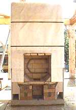
General Assembly
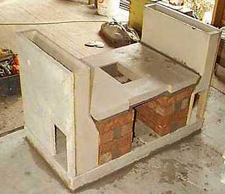
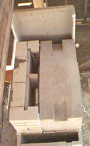
Completed bottom end. Each bottom channel
has a cutout for a heated bench connection
View of rear. Cutout for cleanout opening
is visible at centre bottom of photo,
Rear from chimney side. Cutout for chimney
connection is visible. A 6.5" wide firebrick duct connects the two
bottom channels. The flare in the bottom channels creates a manifold that
equalizes the pressure between the two sides, allowing a side chimney
connection without unbalancing the flows.
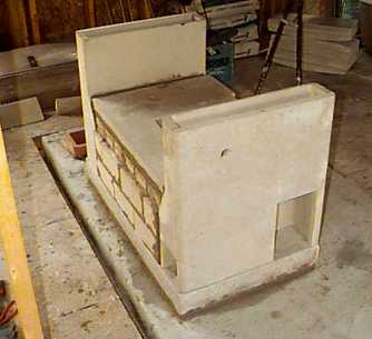
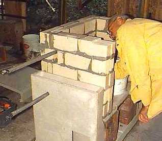
Upper channels installed. Middle channels
are secured with a web clamp. A weighted board stabilizes the upper channels.
The channel lips act as plumb lines for the firebricks.
A 2" X 2" cutout ("gas slot")
in the middle channel will form a direct bypass connection with the chimney,
allowing easier cold starts.
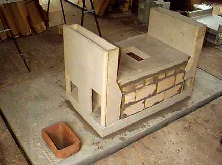
Bake Oven
View of installed oven from top. Throat is
formed by oven and back wall. Back wall is lined with 1" refractory
insulating board to increase heat transfer into oven back
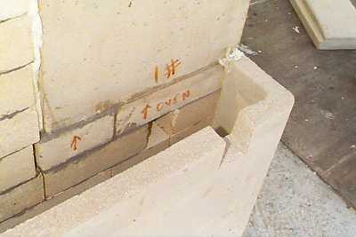
Detail of oven floor bypass (underneath word
"oven"), and gas slot cut into outer channel.
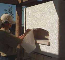
Trimming the fiberglass slip joint material
around the oven. The fiberlass mat is somewhat fragile, so either scissors
or a utility knife with a fresh blade is used.
Domestic Hot
Water
Bottom channel is pre-drilled to accept stainless
water loop, which sits directly in the hottest portion of the firebox.
The slot through the firebricks is patched
with castable refractory patching compound, supplied with the kit.
View of the coil in the firebox.
Also visible at the top of the firebox are
the firebrick heat shields that protect the steel firebox and door lintels.
Heated Benches
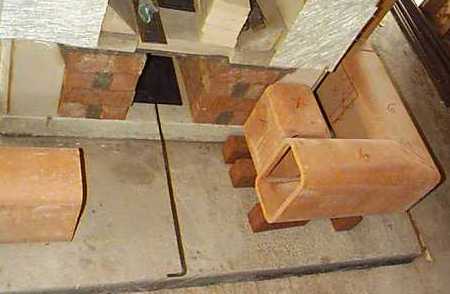
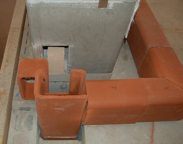
Layout for heated bench that wraps around
the front to the right side chimney. Middle flue liner not shown. An extra-length
handle on the outside air damper (center) passes underneath the 8"
X 12" clay flue liners.
Detail of chimney connection. Flue liner
marked "X" is the inlet from the right channel to the bench.
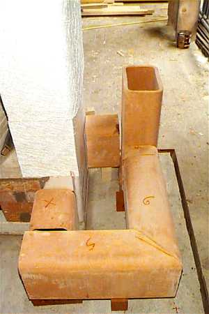
This bench has square corners. Flue liners are cut with a diamond blade
in a 15 amp 7" Makita grinder with a 9" cutoff kit. An abrasive
blade in a skill saw will also work.
Detail of left channel connection. Connection
is angled to clear stone chase for hot water thermosyphon loop to upstairs
tank.
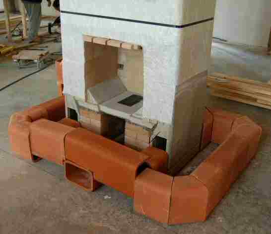
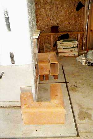
Wraparound heated bench layout.
Note ash cleanout in front, needed for slab-on-grade foundation.
For more details on how to do a chamfered corner, see:
How to do a chamfered corner
(http://mha-net.org/msb/docs/chamfered%20corner.htm)
Bench detail. Section through front bench
and firebox. Bench is shown with a 2" stone top with a 1 1/2"
lip.
In this drawing, the heater is on a slab
on grade, so there is an ashbox below the firebox. A section of 8 X 12
flue connects the ashbox to the ashbox door on the outside of the bench.
The 8X12 bench liner needs to be notched 4" to clear the 8 X 8 ashbox
connection. The insulated base pad is notched out in the ashbox area to
lower the ashbox floor 4".
Below is a front section:
Tuning a Heated Bench
A dry firebrick is set at the normal exit as shown. This forces more gases through the bench, while
maintaining adequate leakage for startup. The firebrick can be adjusted or removed through the
adjacent cleanout door. In this example, the chimney liners go to a cleanout in the basement.
Heated Benches Q&A:
Q: How do you price heated benches?
A: The cost of a heated bench is really the masonry work involved
in building the bench, and the bench top, which can vary quite a bit depending
on materials (cut stone), and complexity (angled corners). Functionally,
it is very similar to a piece of chimney lying on its side.
In pricing a bench, I would evaluate the
cost of materials and labour. An extremely complicated bench (wraparound,
angled corners, trimming and facing the stone top), would probably take
an experienced heater mason and a skilled helper about a day to build
- if it's your first time you could probably double that.
Quite often we will "rough in"
a bench for a client when we install a core that someone else will finish.
This consists of laying it out, cutting the extra openings in the bottom
channels and chimney flue, and making all the cuts in the liners and the
short connecting pieces of liner to the bottom channels. There is usually
a cleanout or two, and if you need access to an ashbox for a slab-on-grade
heater, it adds a little complication. I use a 7" Makita grinder
with a 9" cutoff conversion from Makita and a 9" dry diamond
blade. It usually takes me a couple of hours or so. If it is your first
time, it could take considerably longer. Here is an URL with some bench
photos:
http://mha-net.org/msb/html/assy-hkd.htm
Q:Is refractory mortar used between liners? What else
do I need to know?
A: For heated benches, I use ordinary mortar between the liners.
This is because it is hard to cut liners closer than about 1/4",
sometimes 1/2". They often tend to be warped and out of square a
bit, making them hard to mark very accurately. There is not much heat
stress at the tail end of a contraflow heater, so using regular mortar
is no problem. I also use ordinary mortar around any liner connections,
and slush in mortar in those areas as well.
The mason then simply builds the bench as
if it were a horizontal chimney, except for the benchtop. I tell them
to slush all the connections solid with mortar. The benchtop is usually
2" stone, and it is mortared directly onto the flue liner. For long
pieces of stone, you could create a slipjoint by laying a piece of fiberglass
mat on the liner first.
The benchtop can get fairly hot and the joints
between the benchtop stones have a tendency to hairline. Here is what
I do: use a 1/4" joint, leave it open. Pump the joint full of type
1 silicone. Immediately, dust dry "mortar mix" powder onto the
silicone and press it in slightly. This gives the appearance of a cement
joint, but it is permanently flexible.
Q:What is Type I silicone?
A: Type 1 silicone is the ordinary kind that smells like vinegar,
as opposed to the paintable Type 2 that doesn't have a vinegar smell.
"GE" is the best brand, and we have tested it to 600 F. It is
available at Home Depot and Walmart. I believe it is labelled as "household
caulk" or something like that - it comes in a blue tube. Use the
"clear".
Q:What do you recommend installing around the top and
sides of the clay liner? In my case there is an air space of about 4-5
inches between the liner and the facing of the bench.
A: Normally there is about 1" or less of space. You can
slush it solid with mortar to the front. Don't slush solid in behind.
Q:Can I fill the space with sand?
A: Definitely don't use sand. Slight movements will cause it
to settle and create a wedge, which can crack the bench.
Q:There is only a small space between the top of the
liner and the bench cover - what do I do here?
A: Our bench tops are usually 2" stone. These are mortared
directly to the top of the flue liner. You can lay a strip of leftover
fiberglass wrap on top of the liner, creating a slip joint. Usually there
will be some hairline cracking in the joints between the stones if mortar
is used for grouting. See the above note regarding silicone joints. We
have had 100% success with this method.
Finishing Details

Firebrick "splits" are glued to
the door jamb with G.E. high temp silicone joint at front edge.
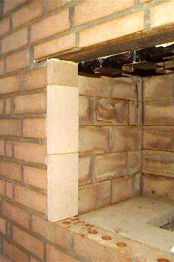
Installed door jamb. Note expansion joint
at top joint with steel lintel. Gap is stuffed with white ceramic fiber.
Other
Rear Exit Chimney Connection:
Detail for rear chimney connection: firebricks are notched and
1/4" x 1.5" x 14" steel bar (supplied) is used to bridge
opening

8x12 flue liner is set dry against opening
when the heater facing is installed. Joint is sealed with common mortar.
Detail of a rear chimney connection with
damper handle extended to allow operation from the front.
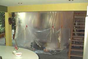
Dust protection for a retrofit installation.
A plastic room is built around work area.
The work area is connected to an exhaust fan sitting in an outside window,
providing negative pressure and preventing the escape of fine dust into
the house.
The clients were living in the house during
the construction, and remarked that they had expected more dust.
Even More Assembly Details
Back to Heat-Kit Assembly Manuals Page
|