Introduction:
As part of our new shop
addition, we built a calorimeter room by insulating all 6 surfaces
of our new office/test lab.
This will allow direct measurement of heat output, and thus efficiency.
This will permit calibration of the stack loss method,which relies on
calculations from gas properties in the stack.
The chemical composition of cordwood changes during the batch burn process,
necessitating a number of assumptions that have never been fully validated
for the specific case of large masonry heaters.
We are changing the combustion air system on the Heat Kit to incorporate
some controllable underfire air, to help speed up the charcoal fire at
the end of a burn.
We have built a new test heater with a prototype air system.
In addition, we have added several other features for testing:
- Clearances to combustibles
- Heat transfer to the foundation
- Stack loss efficiency
- Particulate emissions
- An experimental low-cost heater facing
Description:
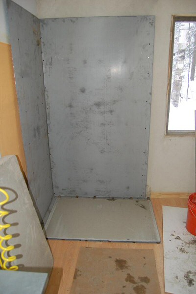
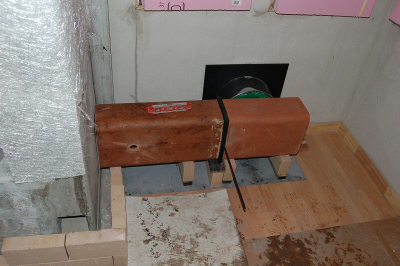
Test corner.
Sheet metal heat shields against the wall, with 1" spacers.
Heater sits on the piece of cement board shown, which is spaced off the
floor with 1"x1" steel tubing.
Steel tubes sit on sheet metal covered plywood subfloor, which sits on
2" styrofoam, on a concrete slab.
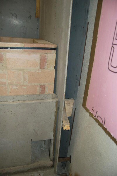
Rear wall detail.
Back facing of heater is replaced with cement board, which is siliconed
to the heater facing (see below).
Clearance to heat shield is 4".
This will allow "worst case" clearance to combustible testing
with the standard 4" clearance.
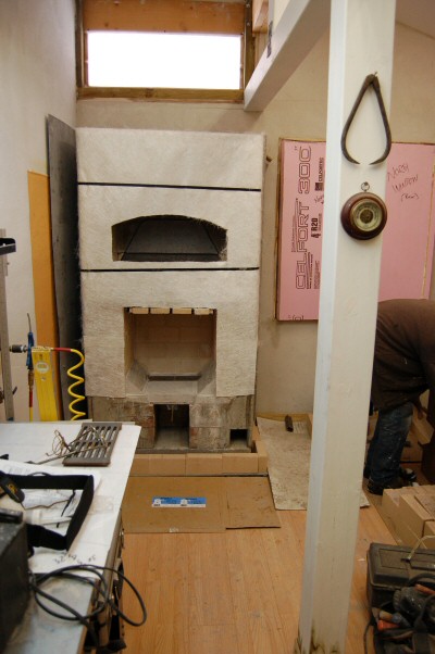
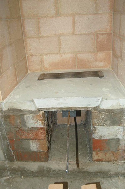
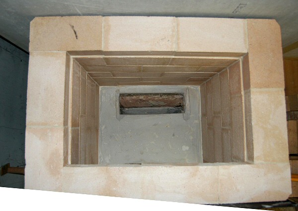
Completed heater core.
Chimney connection is visible at the right.
Heater is vented by an 8" i.d. exterior insulated metal chimney.
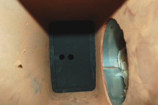
Chimney connection detail.
A short section of heated bench connects the heater and chimney.
Sliding shut off damper is siliconed in between the two flue liners.
A 1.5" round access port is cored into the left liner, for inserting
instrumentation.
Bench is unfaced, for test purposes.
Heater facing will be 2.25" firebricks on edge, with sand/lime slush
to the core. Dry firebrick layout is visible.
Combustion
Air System:
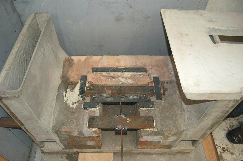
Sliding damper detail.
Damper controls air to small grate, which sits left-to-right at the rear
of the firebox.
In addition to the grate, there is the standard HeatKit air slot at the front of the firebox.
See HeatKit documentation for details.
Comments
and Progress Reports:
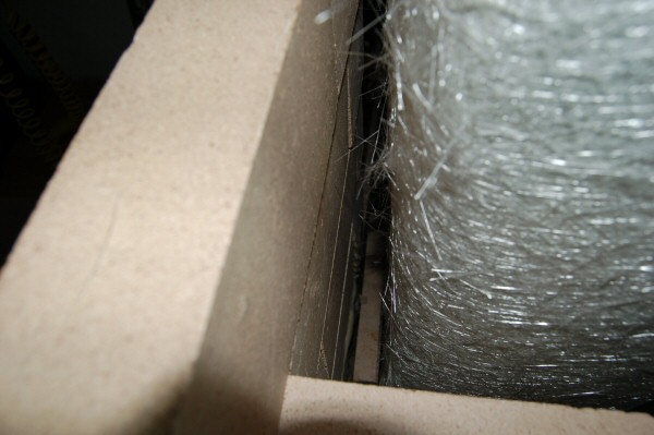
Detail of left side facing.
Facing is 2.25" firebrick with 1" mortar slush, 3.5" total
thickness.
Fiberglass slip joint is visible.
Heater is located 1" from heat shield.
This allows a worst case test for clearances.
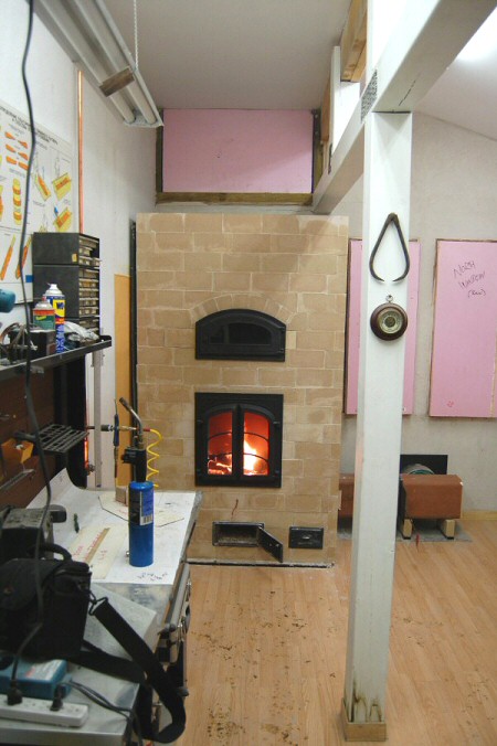
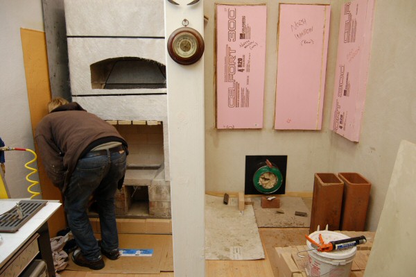
January 19/06 - First Fire
Heater was entirely built by Matt Anderson, a non-professional mason.
February 1/06 - Preliminary Test
The heater is cured.
Gas analysis will be set up soon.
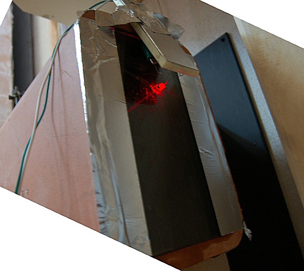
We have set up an experiment to measure particulates by measuring light
extinction in the horizontal flue section
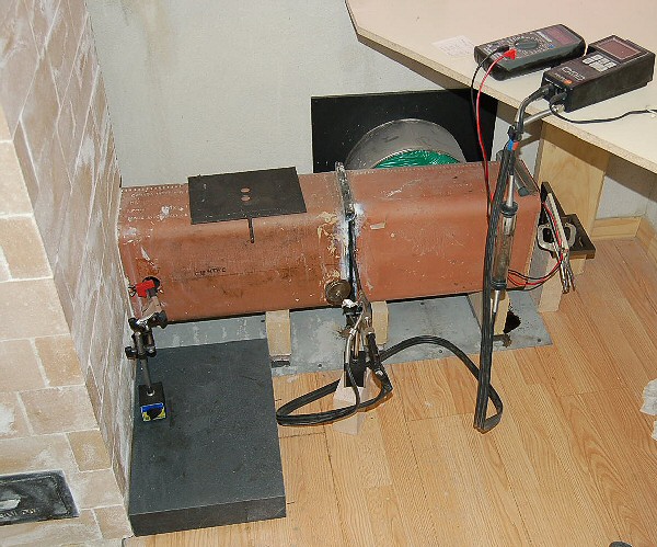
A laser and holder sit on a granite surface plate, which sits on three
pins that extend down to the concrete floor beneath.
Thermocouple probe from the Testo combustion analyzer on the right is
used to measure flue temperature.
The laser is aimed at a 45 degree mirror just inside the flue.
Air drawn in through the hole keeps the mirror clean.
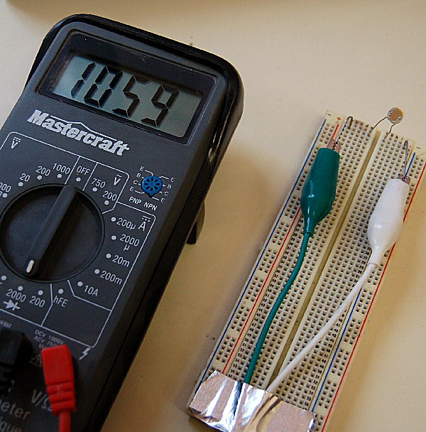
A Radio Shack 276-1657
Cadmium Sulfide (CdS) photoresistor is mounted on a breadboard and
connected to an Ohmmeter.
It measures the light intensity of the laser beam.
The laser beam passes through approx. 36" of flue gas.
A piece of ceramic glass has a 1/4" hole drilled in it and is mounted
to the end of the flue with metal tape.
The breadboard with sensor is aligned with the hole.
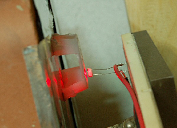
February 13/06: This is the revised sensor setup. The laser hits a plastic
diffuser, and the sensor is about 1/4" from that.
2007:
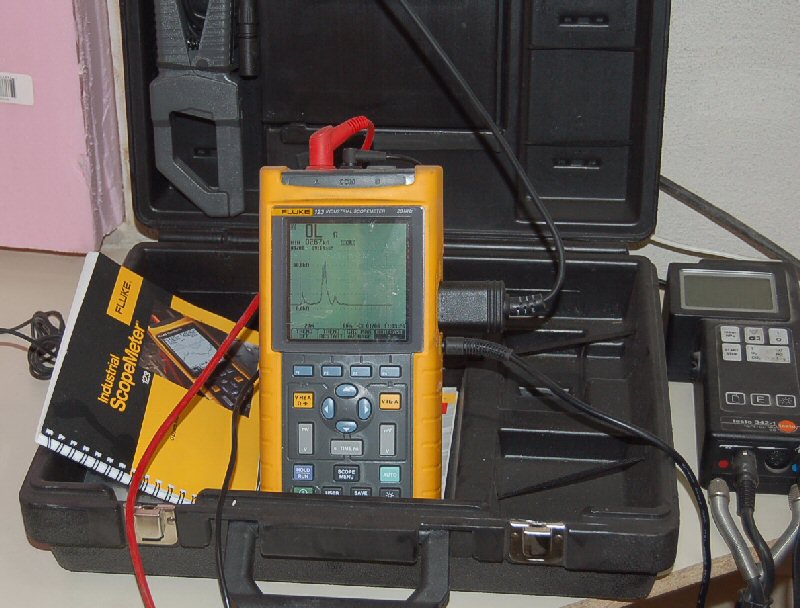
Resistance reading is with Fluke Scopemeter. It has an optical RS-232 interface that runs through a USB adaptor into a laptop for automatic recording of readings.
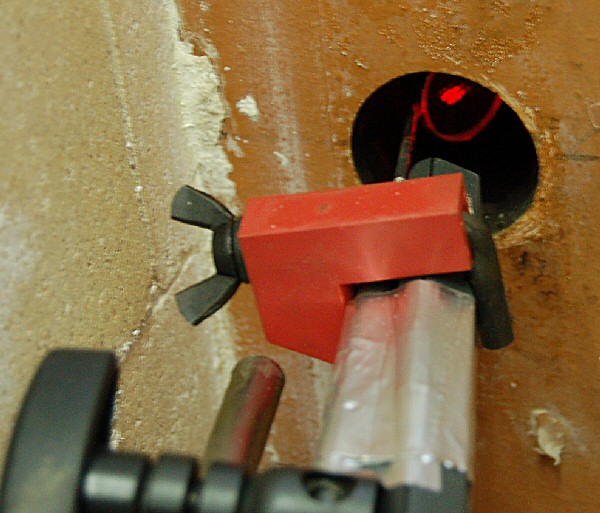
February 18/07
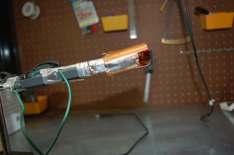
Laser modifications. The mirror has been replaced with one that is silvered on the surface, rather that on the back of the glass.
A copper air channel has been added to direct cooling air towards the mirror and also keep it clean.
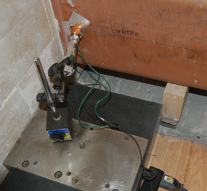
The laser is mounted to a magnetic base sitting on a machined cast iron plate resting on a granite surface plate.
The surface plate has a 3 point suspension resting directly on the concrete slab underneath the insulated wood floor.
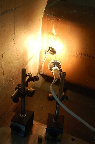
Feb 28/07 New light source: 50 w. halogen bulb.
This has solved CO2 absorption problems with the laser.
Test Results
Technical
background
Links:
Lopez archive of wood combustion technical information
|