
Clearance to Combustibles Testing
at Lopez Labs, Jan. 2000

Introduction
Summary of Results
Conclusion
Plans for Future Testing
Description
Measurement Locations
Results
Temperature Drop Between Heater and Combustible Wall
Data Sets
Thermal Simulation Software
Introduction:Efforts are under way to update the clearances to combustibles requirements for the ASTM Guide to Solid Fueled Masonry Heaters. UL-127 Temperature limits on combustible surfaces are: 90F over ambient room temperature for unexposed (ie., in contact and
covered) surfaces and In order to obtain baseline data to serve as a basis for discussion, we conductrd three tests on an unfaced Heatkit 22" heater core at the Lopez Lab in Shawville, Quebec. Summary of Results:This testing was conducted at an ambient room temperatue of 55F, so the applicable limits would be 145F and 172F. The graph below shows the surface temperatures for a 4.5" thick firebox, 100 lbs fuel (2 x 50lb load, back-to-back). The measurement location shown was 48" above floor level.
ASTM E1602 specifies a maximum surface temperature of 230F on the masonry heater. The tested heater was missing its normal 5" thick facing and therefore generates higher surface temperatures in this configuration. Below is a table with all of the data points from 216F to 280F heater surface temperature, from 3 tests with 3 different fuel loads..
Conclusion:The ASTM E-1602 heater surface temperature limit of 230F with 4" clearance to combustibles provides an adequate margin of safety for a ventilated wall. Temperature on an unventilated wall surface was not measured. Plans for Future Testing:A heater firebox will be constructed and tested at this year's MHA Annual Meeting at Wildacres Retreat, North Carolina, April 16 - 20.(May 10/00: Test Results) Plans call for a firebox with 3 wall sections:
Fueling protocol will be discussed at the meeting. Description of Test Setup:A 4x8 sheet of 1/2" plywood is set with a 4" airspace from the back of the heater. The plywood is closed off at the top, so that air circulation is from the sides only. Measurement Locations:There are 8 measuring points at the centre of the heater back. Heights
from the floor, and a brief description of each point follow: |
12" -- opposite top of connecting duct (underneath the firebox) - 2.5" firebrick 24" -- firebox (bottom) - 4.5" firebrick 36" -- firebox (top) - 4.5" firebrick 48" -- throat - 4.5" firebrick |
67" -- upper firebox, cutout with 1/4" ceramic glass inspection port 75" -- ceiling transition 80" -- ceiling |
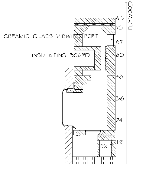
Below are graphs of early results with some comments:
In the graph key, the prefix "H" refers to the heater, and "P"
refers to the plywood
For example, H48 refers to a point on the heater surface 48" above the lab floor.
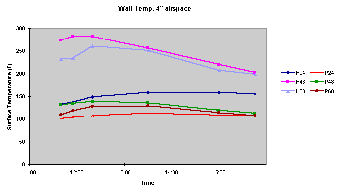
January 19/2000
Heater lit at 9:00 am. 50 lbs hardwood @20% moisture
H=heater P=plywood
Note location H60, which is at the heater throat and has 1" of rigid insulation on the hot face.
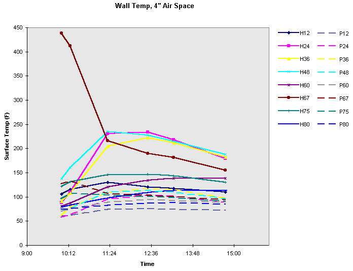
January 20/2000
40 lbs wood. Note H67, which is a ceramic glass viewport.
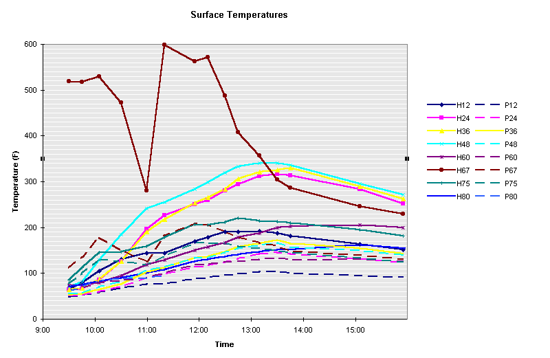
January 21, 2000
100 lb total fuel load - 50 lb first load, reloaded w. 50 lbs at 2 hrs
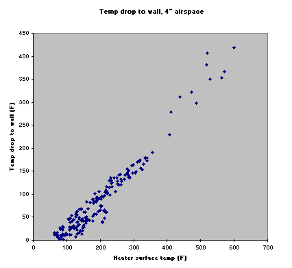
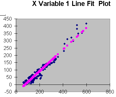
All 185 data points from the 3 tests, above.
Note, that despite the complexity of the heater surface temperatures, and the
time-temperature
relationships, there is nevertheless a reasonably linear relationship in the temperature
drop between
the heater surface and the adjacent plywood surface.
This indicates that, for sufficiently large heaters, it should be possible to determine
safe clearances based on
heater surface temperature measurements alone. This can be done with an infrared
thermometer.
For large heaters (see simulation, below) it should not require a plywood test enclosure
instrumented
with thermocouples, and is thus a lower cost method of acquiring reliable clearance data.
Download the data in Excel 97 format. Check back regularly for updates
Engineering
Problem Solving with Spreadsheet Programs
American Society of Metals
simplified spreadsheet method for modelling heat transfer through furnace walls. See page
5-10
(3.4 Mb PDF file)
WinTherm is a Cross Platform Thermal Modeling Tool for Windows/UNIX computers that ThermoAnalytics developed for heat management design and analysis. This program allows users from any engineering background (thermal or other) to analyze their thermal designs very quickly and accurately using the unique features of the user interface. The intuitive arrangement of the user interface permits both novice and expert users to set up and analyze thermal systems with a minimum of user input.
WinTherm
4.0 has been released. |
Here's a simulation in Wintherm 5.0
(demo version), with an 8" thick firebrick wall held at 1000C
indefinitely on the hot side. There is a 4" air space and then a wall (wall
temperatures shown in color).
This is would be much worse case than a UL test.
Shown are the steady state wall temperatures, using a convection coefficient of 10 W/m^-K.
The dimensions for both panels are 52" wide x 86" high (typical brick contraflow
heater).
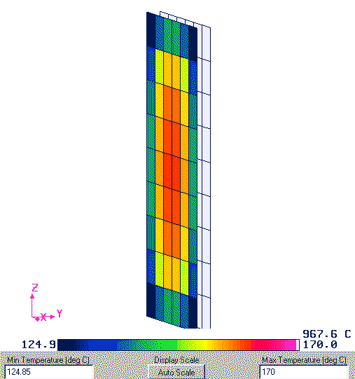
The two surfaces are suspended in mid
air, ie., the cavity is not closed off at the floor.
Note that there are edge cooling effects, but that the centre shares characteristics with
an infinite plane
at a constant temperature. With large masonry heaters, the predominant parameter
is the heater surface temperature, and the combustible wall temperature can be assumed to
lie in the middle portion, as above.
For small, hot heaters, edge effects
will dominate, and combustible wall temperatures will be
lower than an infinite plane model would predict. In this case, a clearances to
combustibles
test with a plywood enclosure is required. Alternatively, it can be reliably modelled in
Wintherm
once there is adequate calibration data for the convection coefficients.
A good first approximation for the
convection coefficients can be derived generically - see,
for example, ASHRAE Handbook of Fundamentals, Chapter 3. A very precise model would
require validation data from a recognized lab.
Also see muffler demo, below.
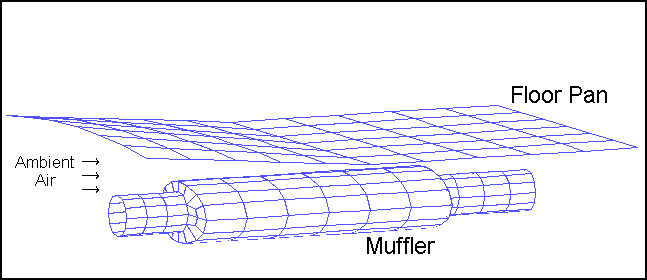
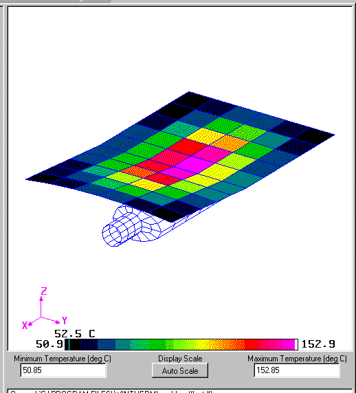
Automobile Floor Pan/Muffler assembly. The assembly has the boundary conditions and properties listed below. Ambient air is flowing between the Floor Pan and Muffler. Compare the temperature of the center of the Floor Pan for the following two cases:
Schematic:
Known:
Here's a screen shot of the muffler simulation, very similar to masonry heater clearances to combustibles. The surfaces are represented by meshes, but they can have properties such as thickness, heat capacity, conductivity, etc. 3 layer composite walls (for example, firebrick, ceramic blanket, face brick) are easy to do.
This page last updated on June 1, 2008
This page created on January 20, 2000