Refractory Core Maine-Et Loire 2006
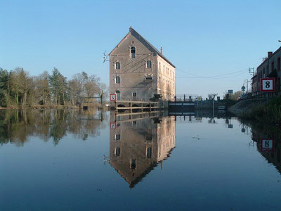
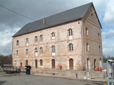
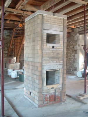
After detailed preparation. I arrived (late March) on site in Anjou not far from where the rivers meet. The object was to build a Finnish style contraflow refractory core. Located on the second floor of an industrial water mill that was undergoing complete renovation.
The core would contain 750 42% Al So refractory brick and 100 common brick along with fourteen 25kg bags of castable refractory concrete. There would be an auxiliary indirect bake oven incorporated in the upper chamber.
The core would be built to take Upo s 0018 fire box door, and
0213 oven door.
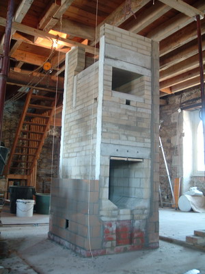
It would be faced in clay brick by the client.
Note: Any images or notes regarding projects inspired or assisted by this article, if sent to Pyromasse, will be posted on to a page specially created for such comment.
See Also: Materials
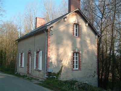
The buildings on the opposite side of the lock are, foreground, the granary, and background, the lock keepers house.
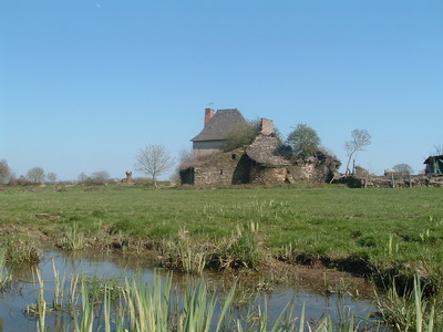
View of ruined and more modern farmhouse on the river.
Note the bread oven adjacent to the ruined farm buildings.
Much of the old machinery survives intact.
Power Train Machinery (6 images)
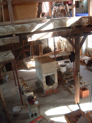
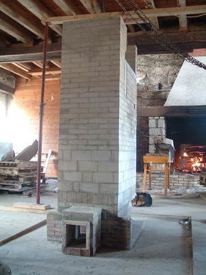
Today the mill is divided into two separate dwellings. The project was undertaken in the dwelling occupying the left half of the building.
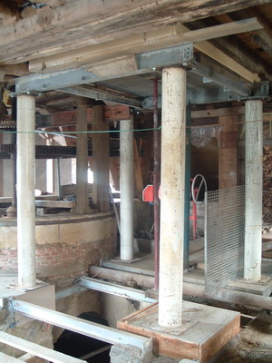
The footings and foundation of the building are exceptionally well built as the structure had to withstand weight of the upper floors, the vibration, of machinery and the erosive action of the water running through the channels.
View alternate image of foundation
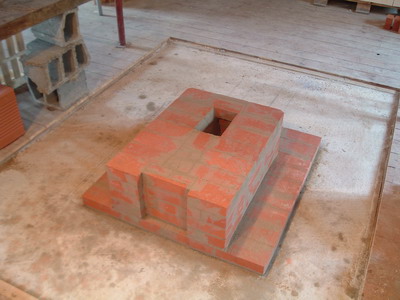
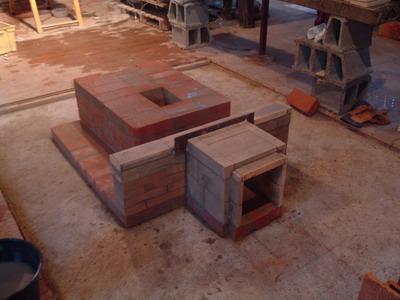
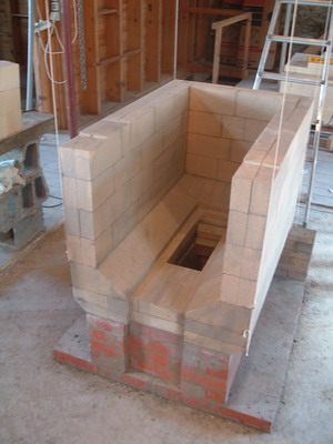
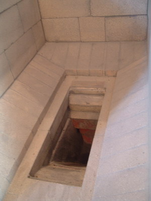
The rectangular hole allows the ashes to drop through the foundation slab into a depositor.
The recess in the front forms a combustion air intake channel allowing combustion air to enter by the cast iron air intake door installed on the facing, and be deflected, by the refractory brick deflectors, on to the fire.
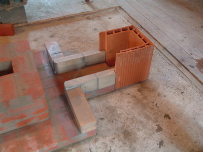
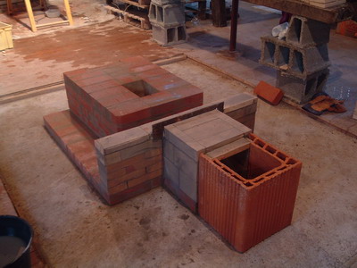
The rear wall is at the same height as the first 4 rows of clay brick.
The subsequent rows of refractory brick, forming the hearth, are of crucial importance in strengthening this masonry and angle iron lintel. This is a potential point of weakness though cannot be avoided.
Work needs to be done with the utmost of care.
It would be removed during construction of the core.
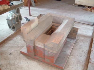
The opening in the fir box floor is cut to take the Upo 0413 cast iron grate.
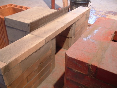
Recesses are ground or cut into the top two bricks at the front of the fire box walls. This allows the angle iron lintel to sit flush with the top of the bricks forming the rest of the fire box walls.
This heater does not use the Ventura effect to encourage secondary combustion. The wide vertical through running up the rear wall acts as a fire tube.
The small sections of angle bar welded to the angle bar lintel, will hold refractory brick splits that will act as a thermal shield, protecting the angle bar lintel itself.
As the heater's fire box is exceptionally deep, and the over air draught blows the fire towards the back of the fire box, the angle bar lintel receives little or no flame bight. The lintel would also be ok without the added heat shield.
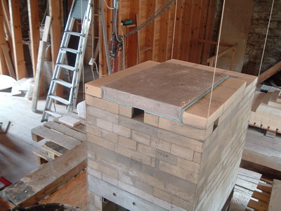
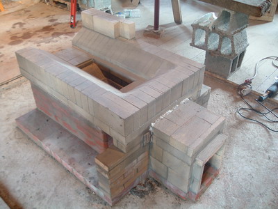
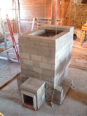
I have never found this to be necessary though at 1m. this was the deepest core I had built, and thought the addition of an inspection opening prudent.
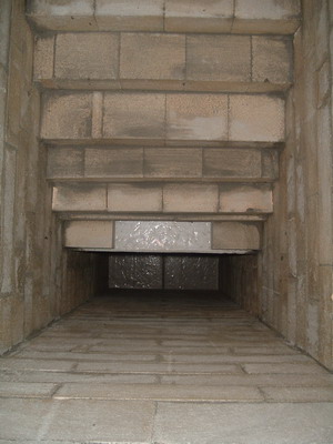
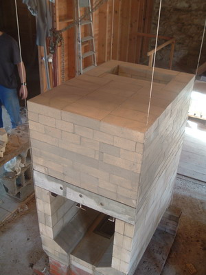
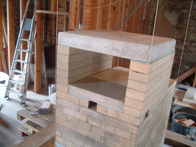
The refractory concrete capping slabs can be seen in the background.
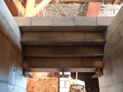
The fire tube running up the rear wall.
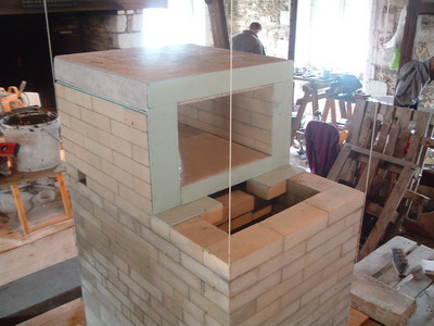
Corbelled ceiling and bottom of the castable slab that forms the rear wall of the oven.
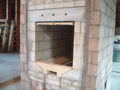
The angle iron lintel is fitted with two half refractory bricks that will act as a heat shield.
The two refractory brick that are dry layed at the front of the hearth are used to deflect primary air on to the wood load at a 90 degree angle.
Pyromasse, Montreal. April 2006
