These images and text describe the construction of a North American version of the traditional Finnish masonry cookstove.
Rather than the series of lower channels found in the original stove, there will be a bell captivation chamber that will also extend up into
the space normally used for the oven in the upper section. The oven has been eliminated from this design to allow the construction of a more robust fire box, and complete double skinning of the stove. Double skinning also eliminates the necessity to use clay mortar on the facing, and has the stove conform to North American norms. The cookstove will eventually have a rendered finish applied by the home owner.
The double bell principal was pioneered in the 1920s by Russian engineers Ieosif Pondgorodnikov and W.E. Groume-Grjimailo.
This particular model was arrived at after building the prototype described in Cookstove Construction Notes, and consultation with contemporary stove-builder, and exponent of the double bell principal in North America A Chernov.
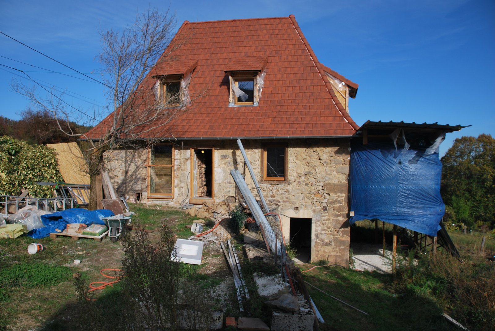
The Site. The building is about 300 years old. It will eventually be insulated from the exterior to preserve the inertia of its 70 cm thick masonry walls.
Materials
Ceramic Blanket:
Superwool 607 HT 13mm
Castable refractory concrete:
Refcast 550/10
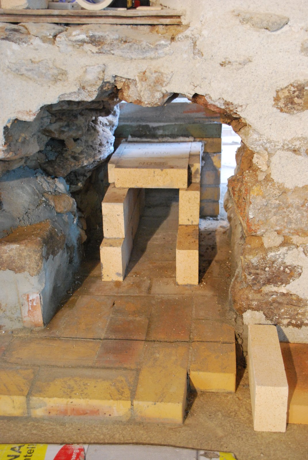
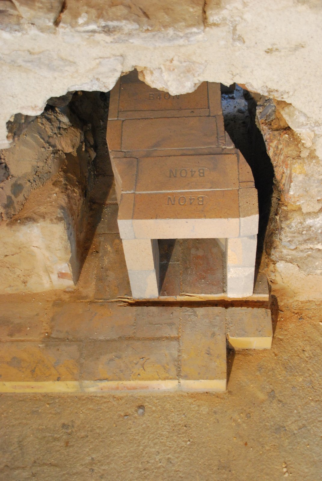
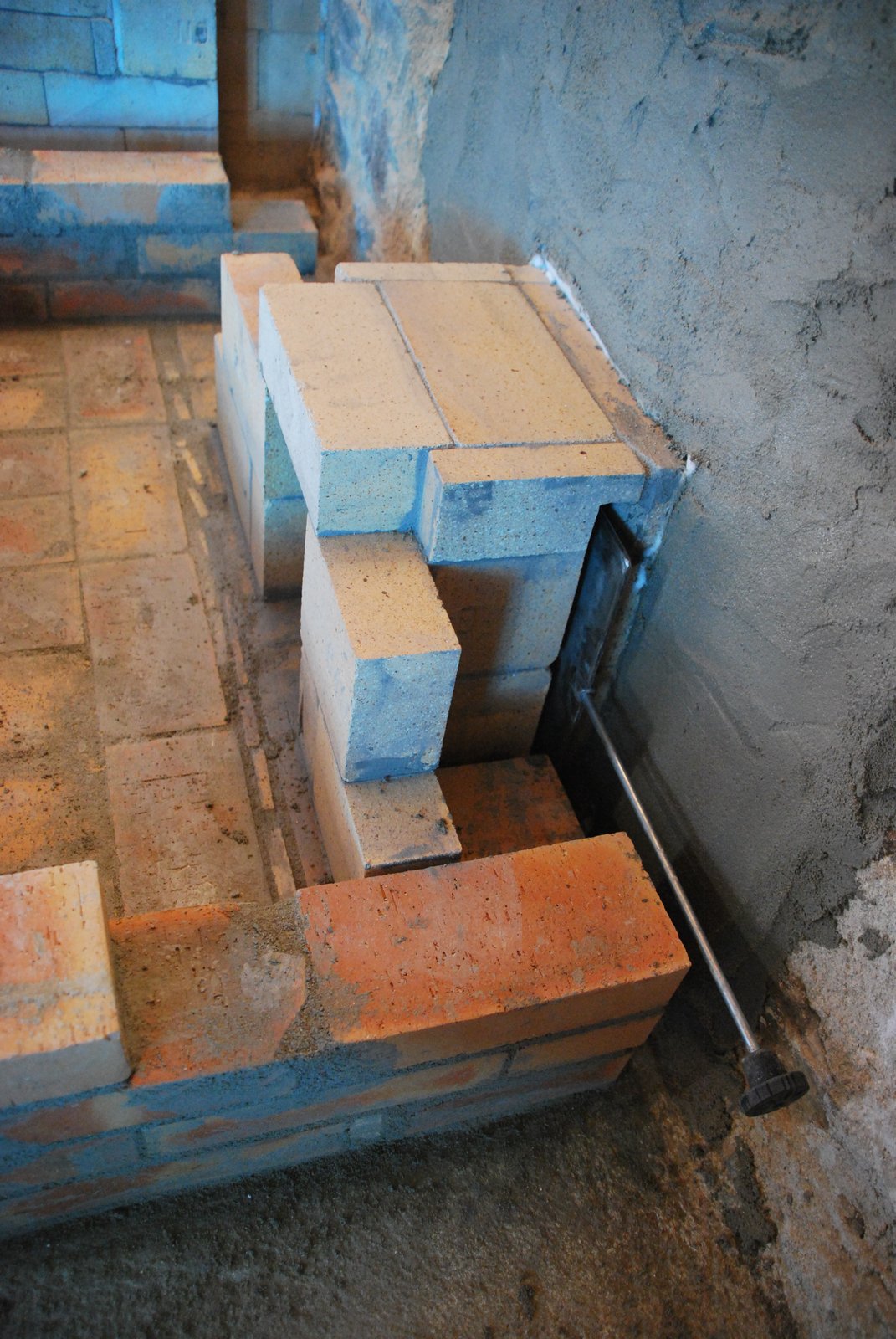
The cookstove's transmission tunnel coming from the chimney on the far side of the 70cm earth and stone wall.
The tunnel bends to the right to gain some room in regards to where it will be connected to the cookstove.
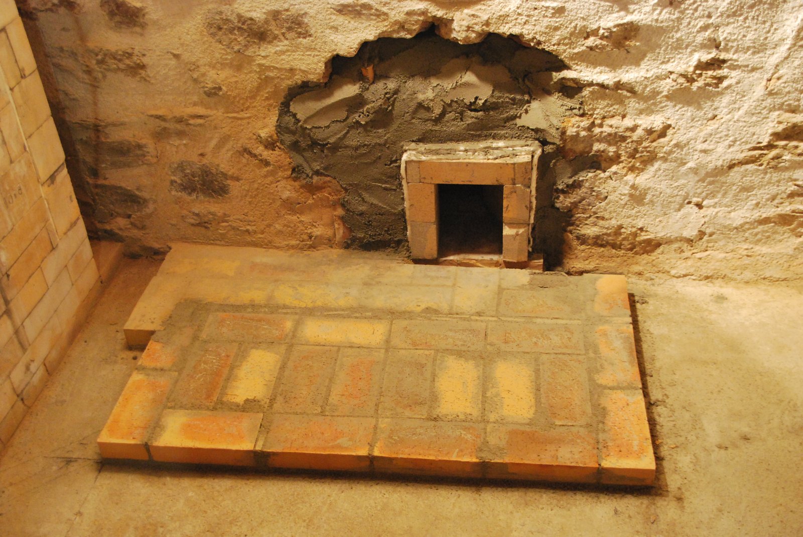
The groove is cut to take the damper and the corners of the brick in the wall cut back to allow smooth operation of the damper.
(For detailed installation of the damper in the tunnel of the accompanying heater see Chimney Connection #11)
The wall is closed around the gasketed tunnel.
Several courses of facing are layed before construction of the connection.
The damper frame plate is installed in the connection of the tunnel to the wall of the cookstove's bell.
The second course of the connection.
The bridged connection. The damper guillotine plate is in place. The location of the damper here is necessary as it needs to be operable from the cooking station.
Temporary cardboard gasketing is inserted before laying up the facing around the connection.
A band of wool will act as a smoke gasket and expansion gasket.
The facing layed up to the height of the connection and the cardboard removed.
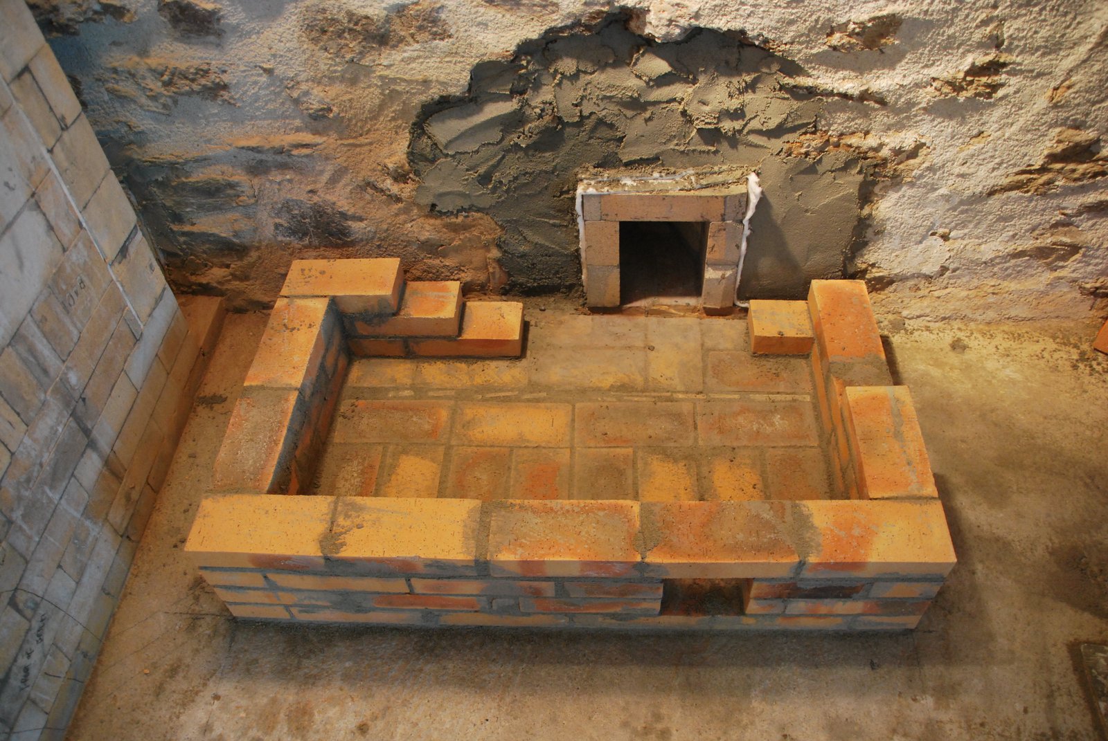
The facing bridges the connection on two pieces of salvaged angle bar. 8 courses of facing are layed before building the lower portion of the captivation chamber.
The exit opening in this case would be better if located more towards, or in the right rear corner. The position of the hole in the wall behind the stove, though needed to be respected.
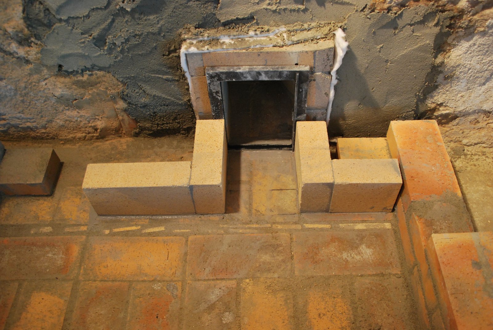
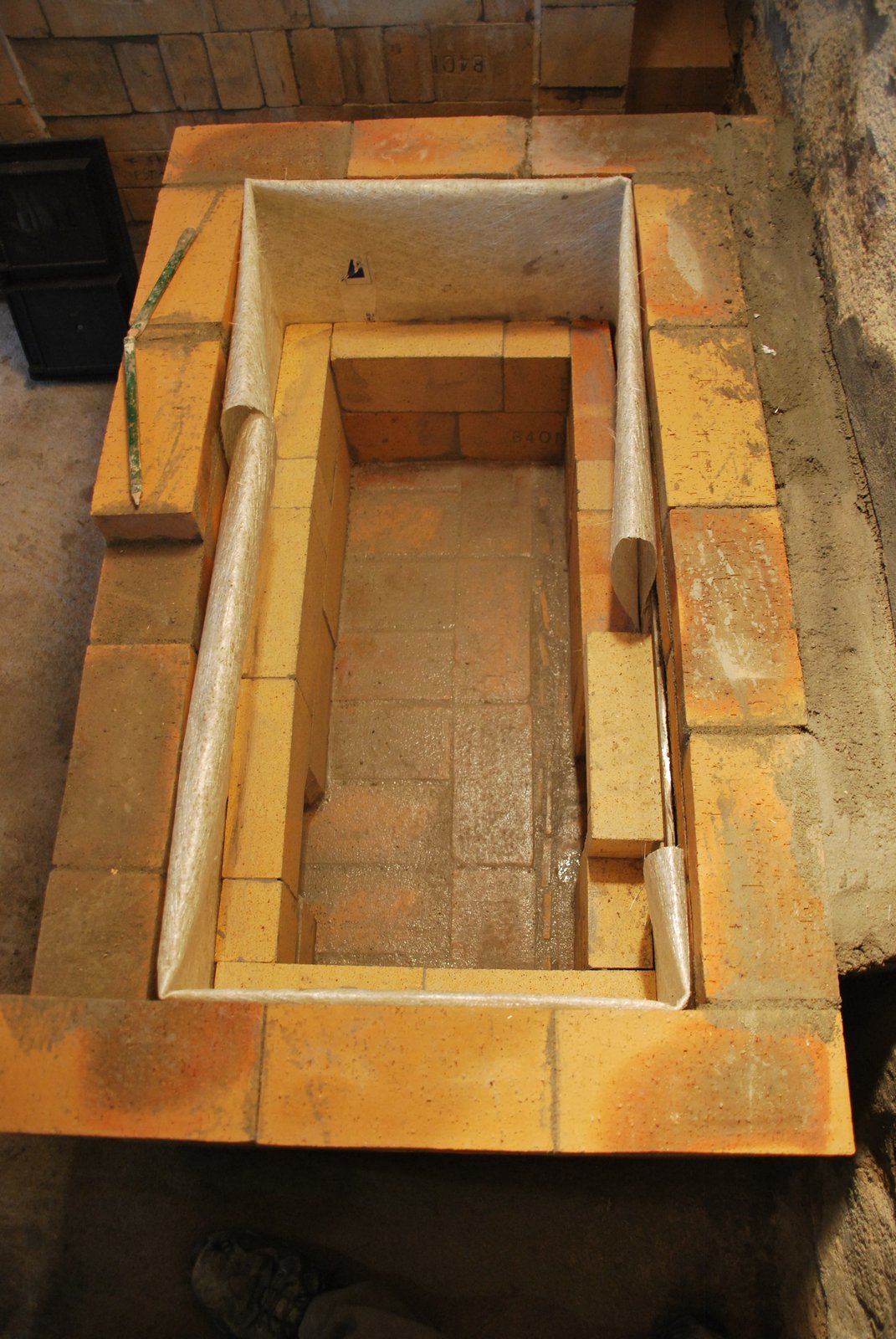
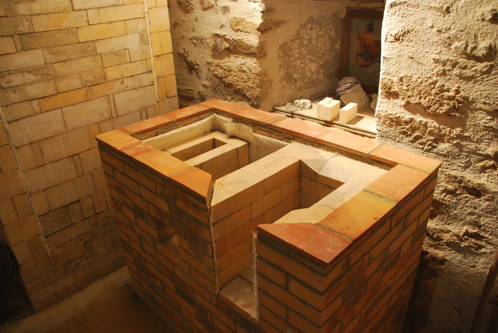
The first 2 of the 3 shiner course that form the chamber.
2 sheets of glass mat are used as an expansion gasket between the walls of the chamber and the facing.
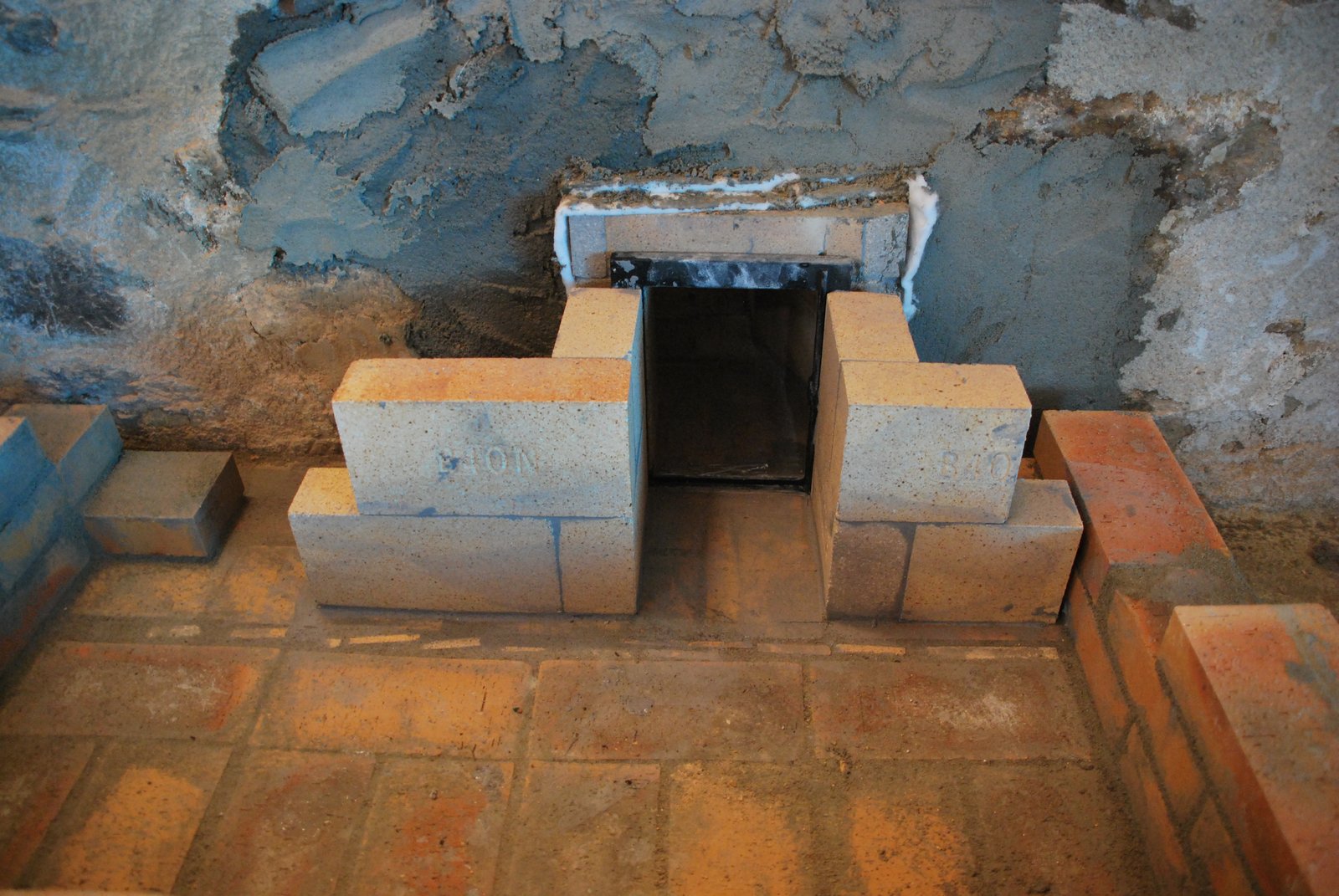
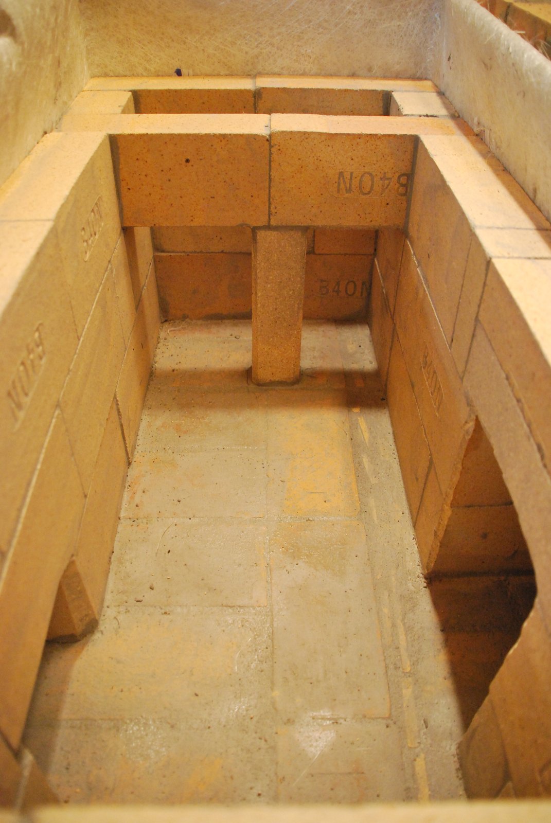
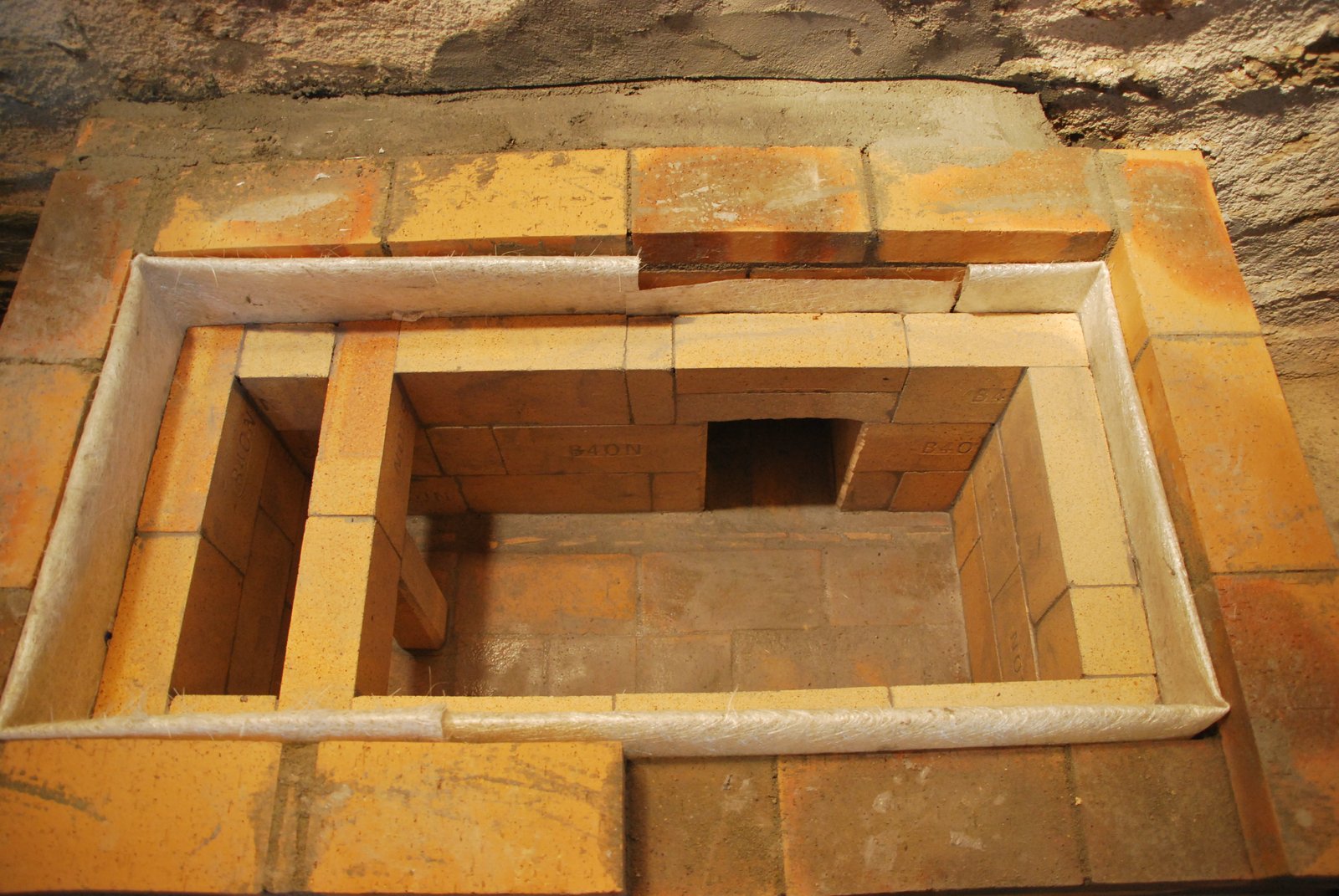
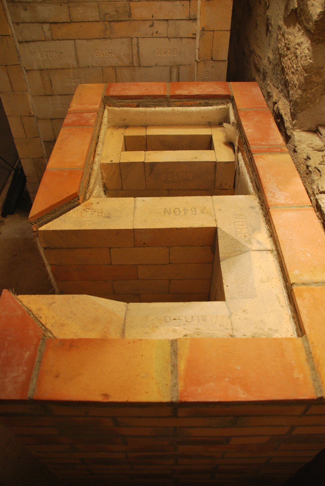
The completed lower portion of the chamber. The support pillar on the down channel wall is slightly to the right of centre to encourage flow to be primarily to to the left.
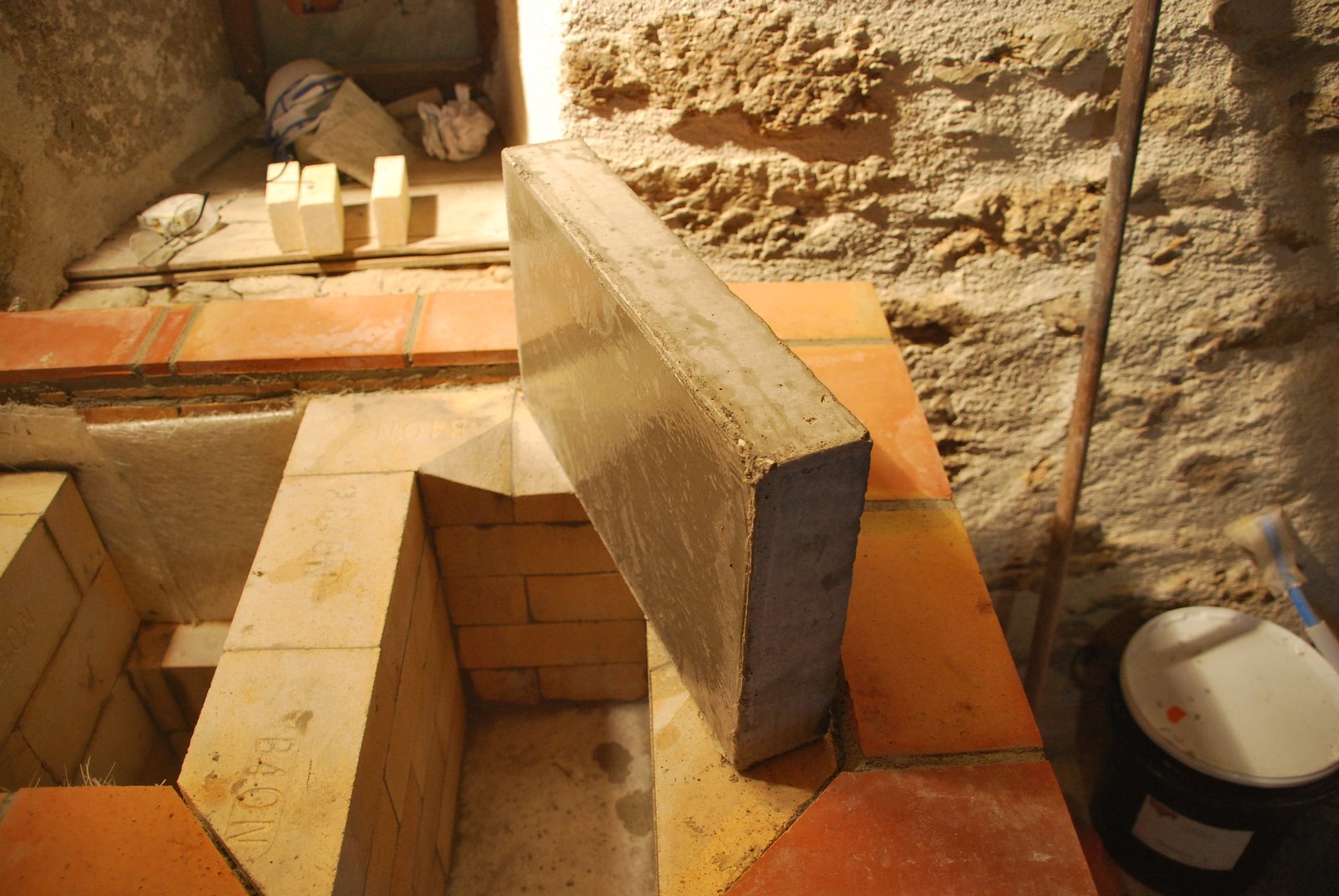
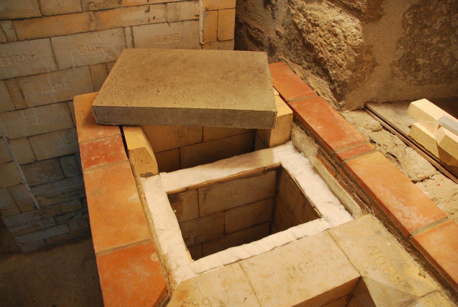
An 8 cm thick castable refractory concrete slab is used to close the lower chamber. It is upon this slab that the fire box will stand, and the dimensions of the slab represent those of the fire box.
A fire brick deflector is held in place by the fire box support slab. The deflector will slow down the flow and deflect it away from the exit opening.
The slab, as with the whole core of the cookstove is gasketed from and independent from the facing.
4 sheets of glass fiber mat are used as a gasket between the facing and fire box. It is held in place temporarily with brick.
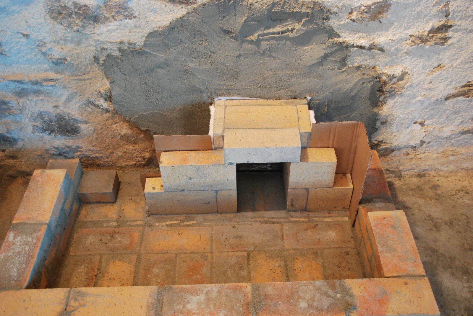
The first course of the fire box. The walls of the chamber and the down channel are gasketed with two sheets of glass fiber mat.
The last course of the fire box.
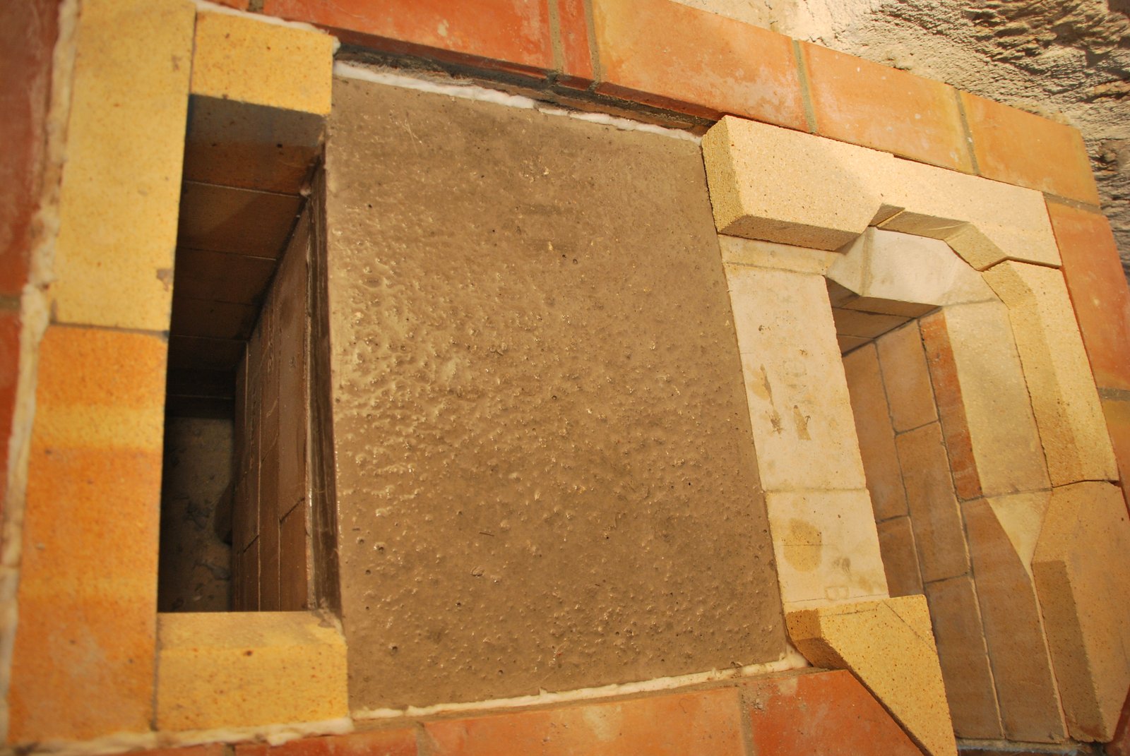
The clay tile is the last course of the facing on to which the cook top frame will rest. It is layed 1cm proud of the facing to allow for the brick surface to be rendered.
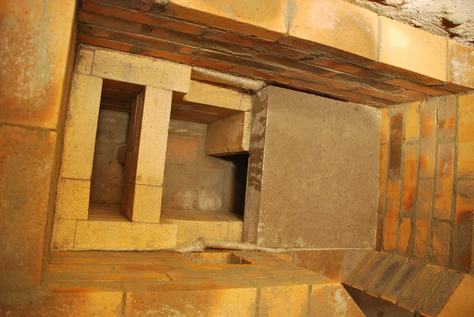
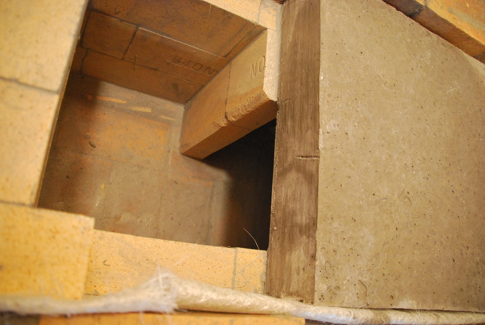
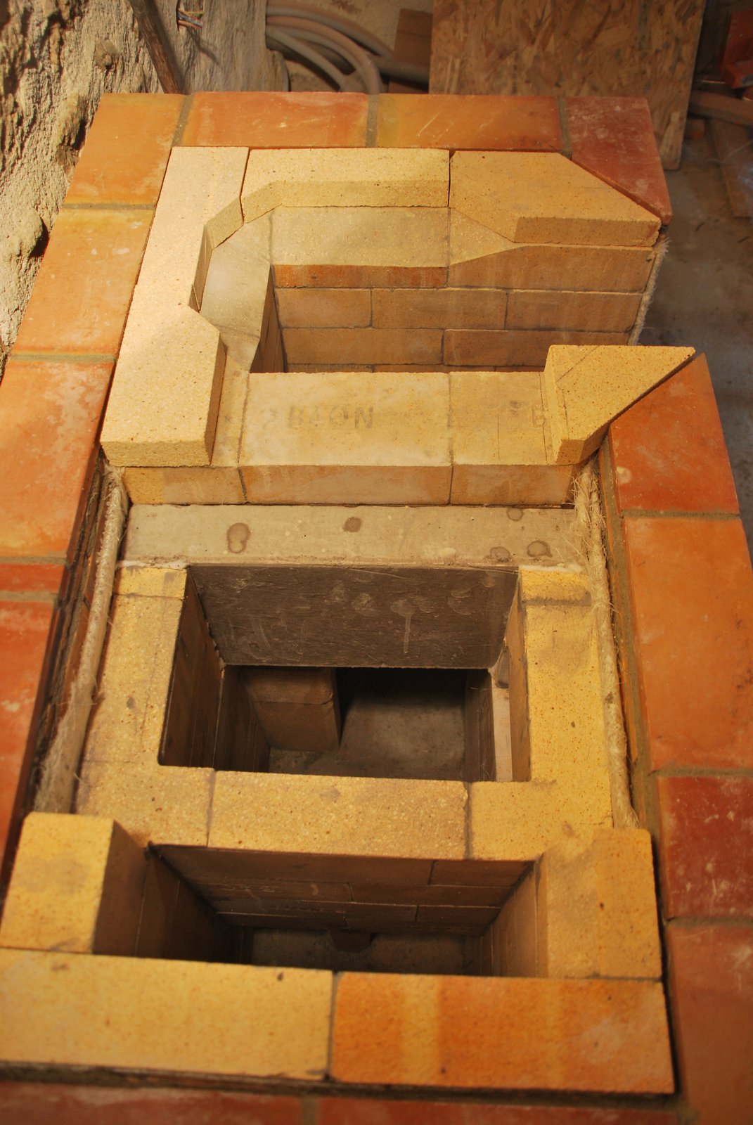
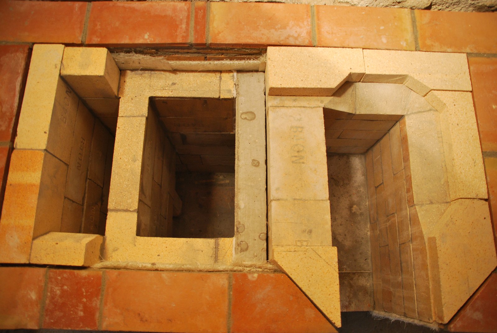
The opening to the left of the fire box loading opening, allows access to the upper section of the chamber.
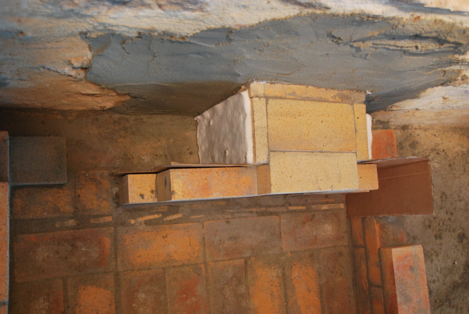
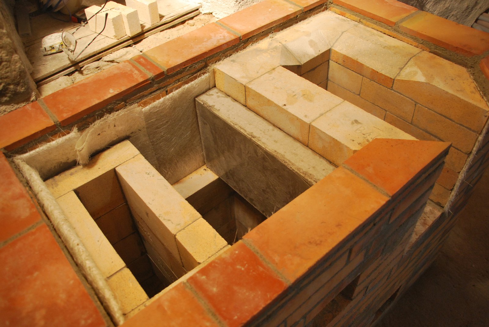
A refractory concrete slab is cast to be used as a support lintel for the chambers capping slab.
The slab is layed dry. It serves to support the capping slab, and avoid having it rest on the fire box wall, keeping the firebox independent from the chamber.
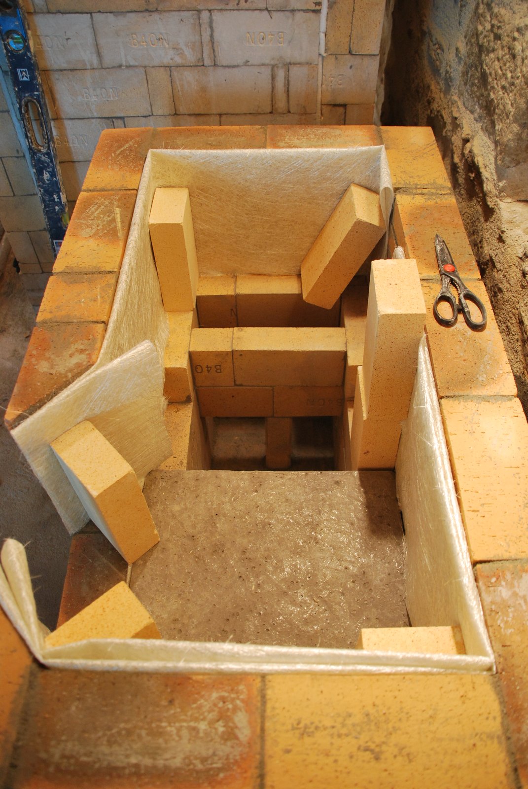
The walls of the chamber are layed in shiners, that are gasketed from the slab with wool.
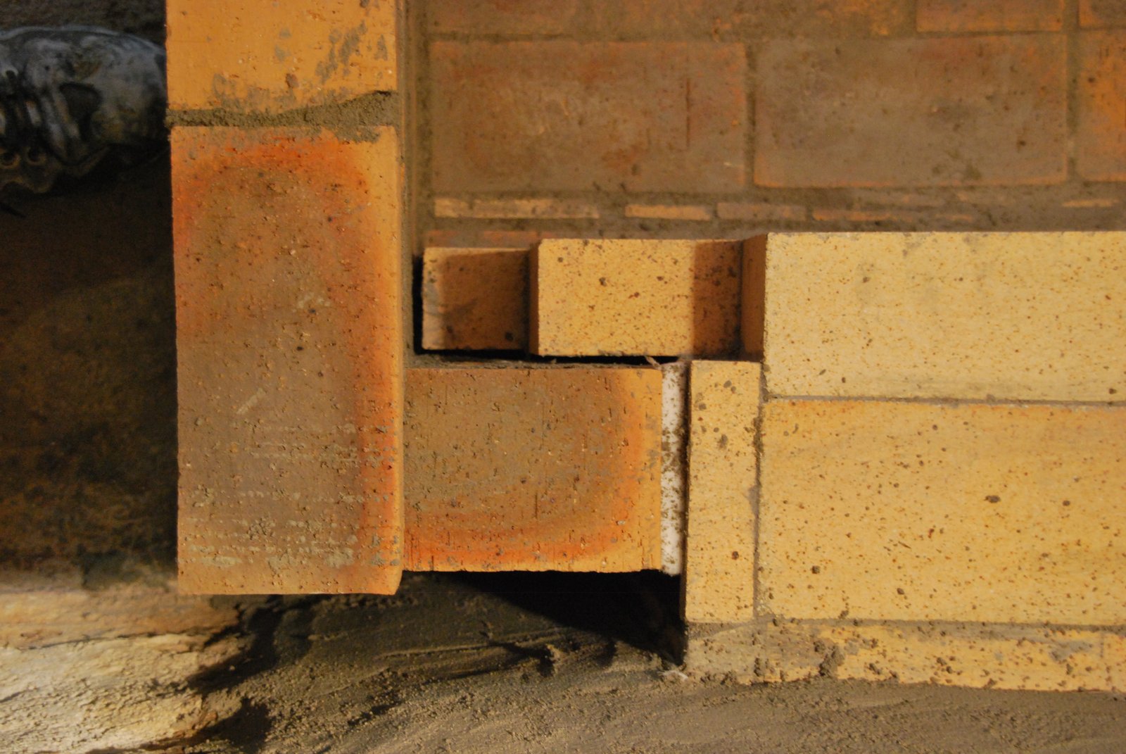
The last course of the fire box walls is layed dry. This gives the advantage that it can easily be adjusted or moved once the stove has been lit and the precise actual smoke path has been seen. If layed in mortar they would brake bond and become loose during the first few fires.
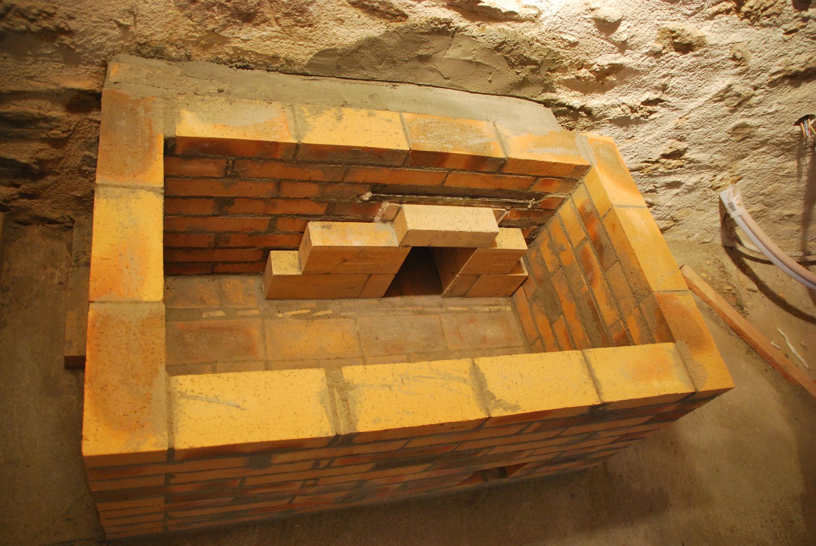
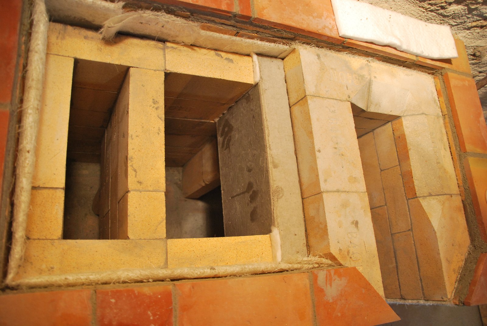
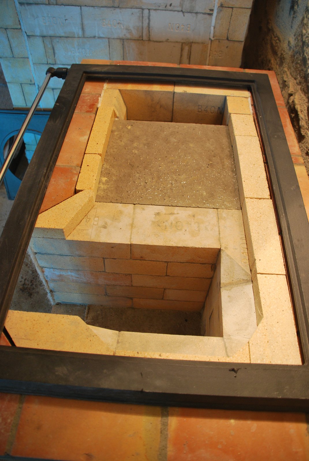
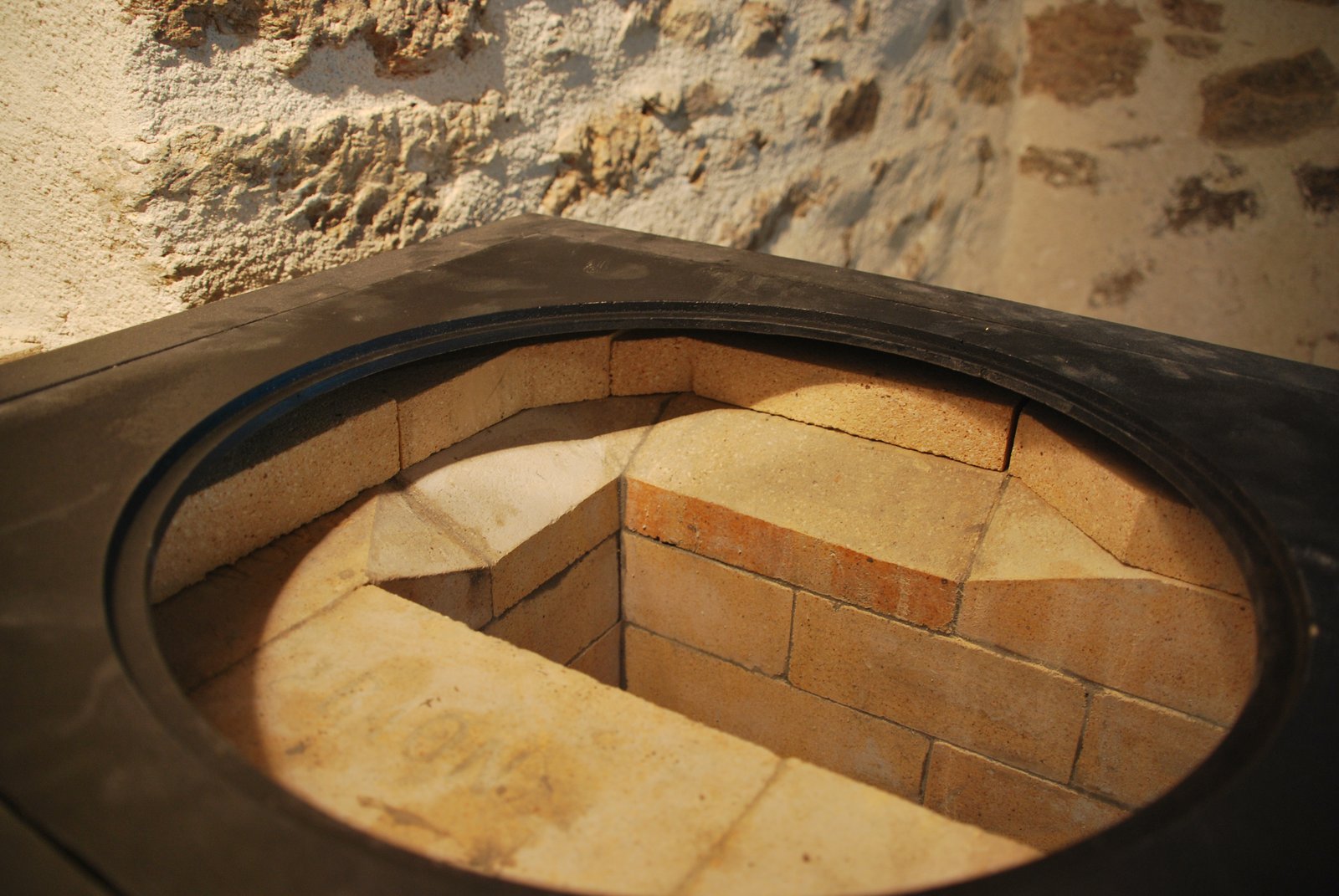
The upper portion of the chamber before it is closed with the capping slab.
The castable refractory concrete capping slab, ready to be layed on to the gasketed upper surfaces of the chamber walls. Here 13 mm wool torn in half was used as a gasket. It is important that this interface does not leak.
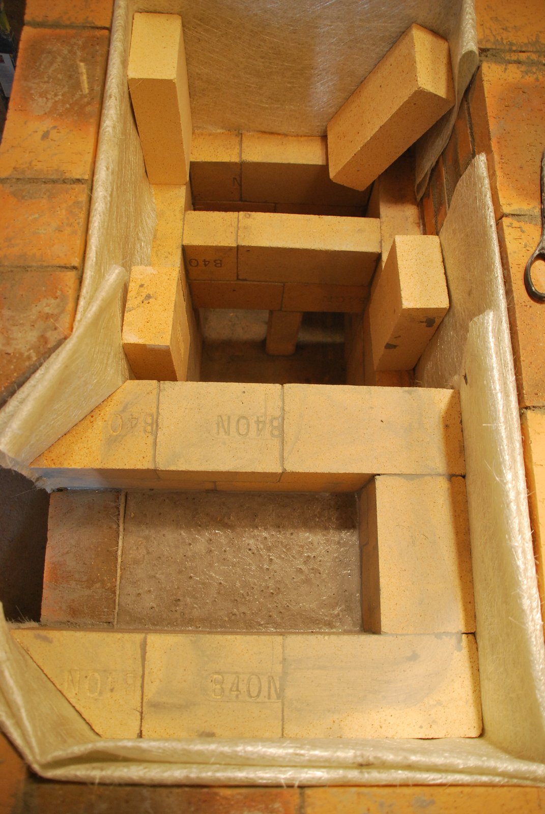
The sharp corners have been left on the inner edges of the smoke path, i.e. The left side wall of the fire box and the left edge of the slab, as turbulence at these points would help throw flame up onto the plates.
Strips of brick are cut and layed dry on the slab against the facing. These will shield the facing, guide the flow precisely beneath the plates, and make the stove entirely double skinned.
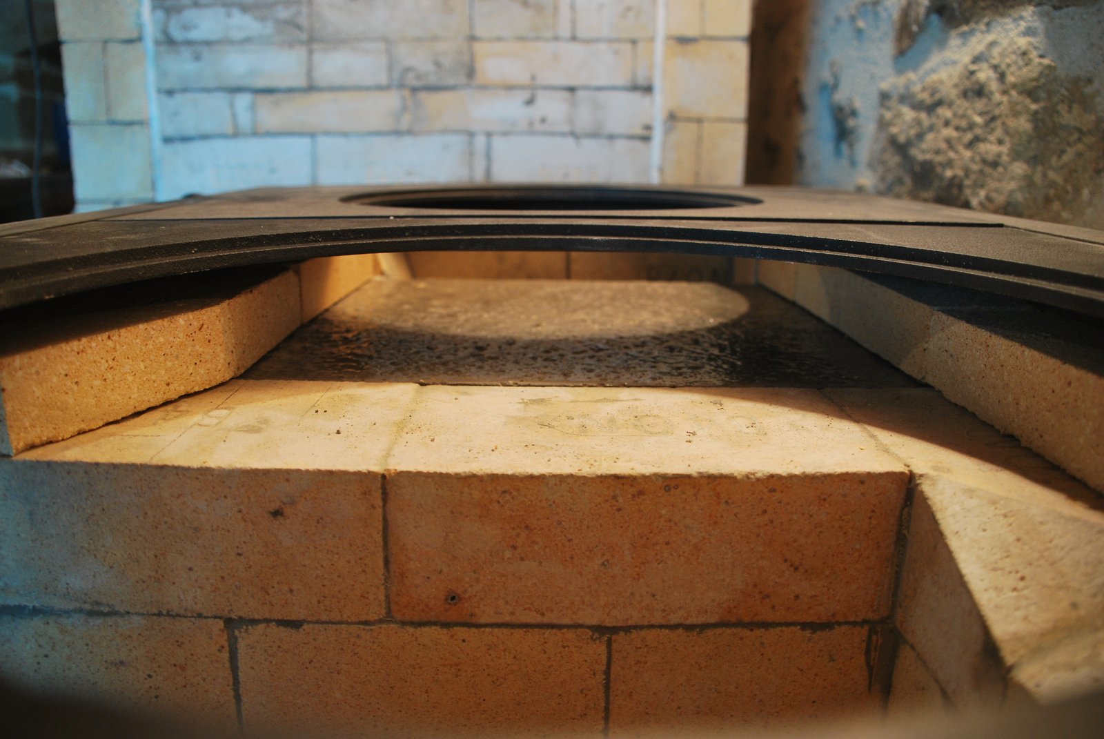
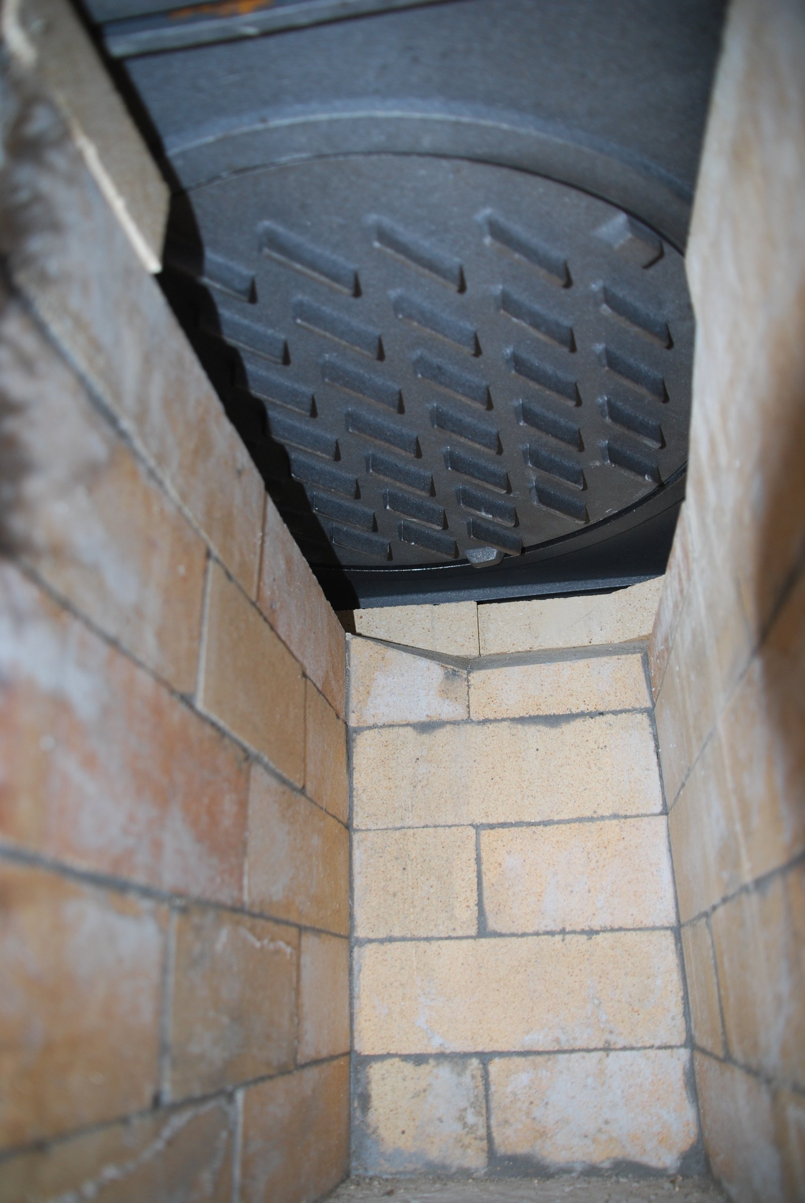
View of the smoke path from the fire box.
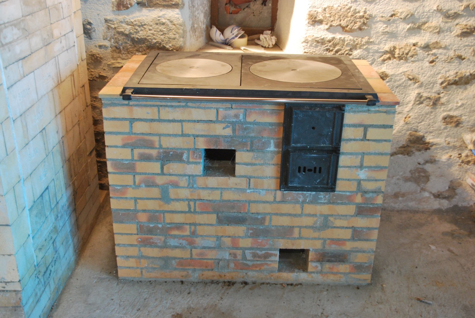
The position of the large plate. This needs to be considered as the cook top and fire box door are designed for traditional single skinned East European cookstoves. In this case the overall dimensions of the stove have been expanded. The front of the cook top has to be level with the front edge of the facing, as it is the cook top which holds the fire box door in place.
The large plate is deliberately back and down flow.
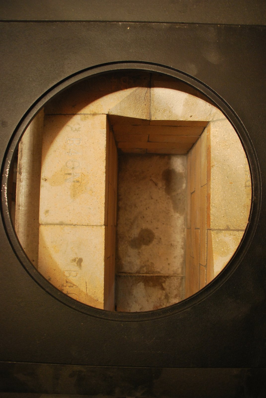
The last course of dry layed brick of the fire box.
Inside the fire box/ash box. The grate has yet to be installed.
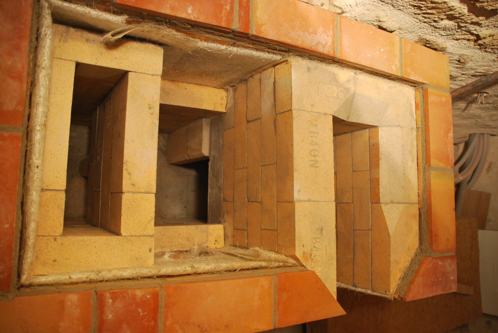
The facing will be rendered by the home owner. The hardware is installed temporarily to assure that everything lines up. The lower opening gives access to the lower portion of the chamber, and through the transmission tunnel to the base of the chimney on the other side of the wall. The higher of the two openings gives access to the upper portion of the chamber. Certain areas of the lower chamber can also be accessed by the down channel. Full access is important for cleaning.