The aim of this project was to build a simplified version of the standard European masonry cookstove with a lower ‘Bell’ captivation chamber rather than traditional heat exchange channels.
Having no bends and a large capacity ‘in’ and ‘out’ channel, the bell should increase the draw and reduce the risk of spillage through the cook top, while offering more surface area for captivation.
This variant of the traditional cookstove is inspired by the investigations of IS Podnerodnikof and W.E. Groume-Grjimailo.
The entire core of the stove, i.e. both lower and upper portions, will be physically independent of the facing. This allows the facing to be layed in type N mortar and enables it to be fired longer, with less risk of damage to the facing.
Eliminating the oven will offer more space in which to build a considerably stronger fire box from brick layed flat rather than as shiners, allow all outer surfaces of the smoke path to be double skinned, and permit a simplified and more robust construction.
The cast iron cook top to be used is designed to be installed on a traditional single skinned stove and so the format of the cook top and position of the hot plates presents challenges in terms of overall dimensions, and position of the fire box, for this enlarged version.
The stove will be served by an independent 9 inch round clay flue liner tile with a guillotine shut off damper at 5 feet. Cookstoves should be served by their own independant chimney flue.
All images have an HD option. Click on image.
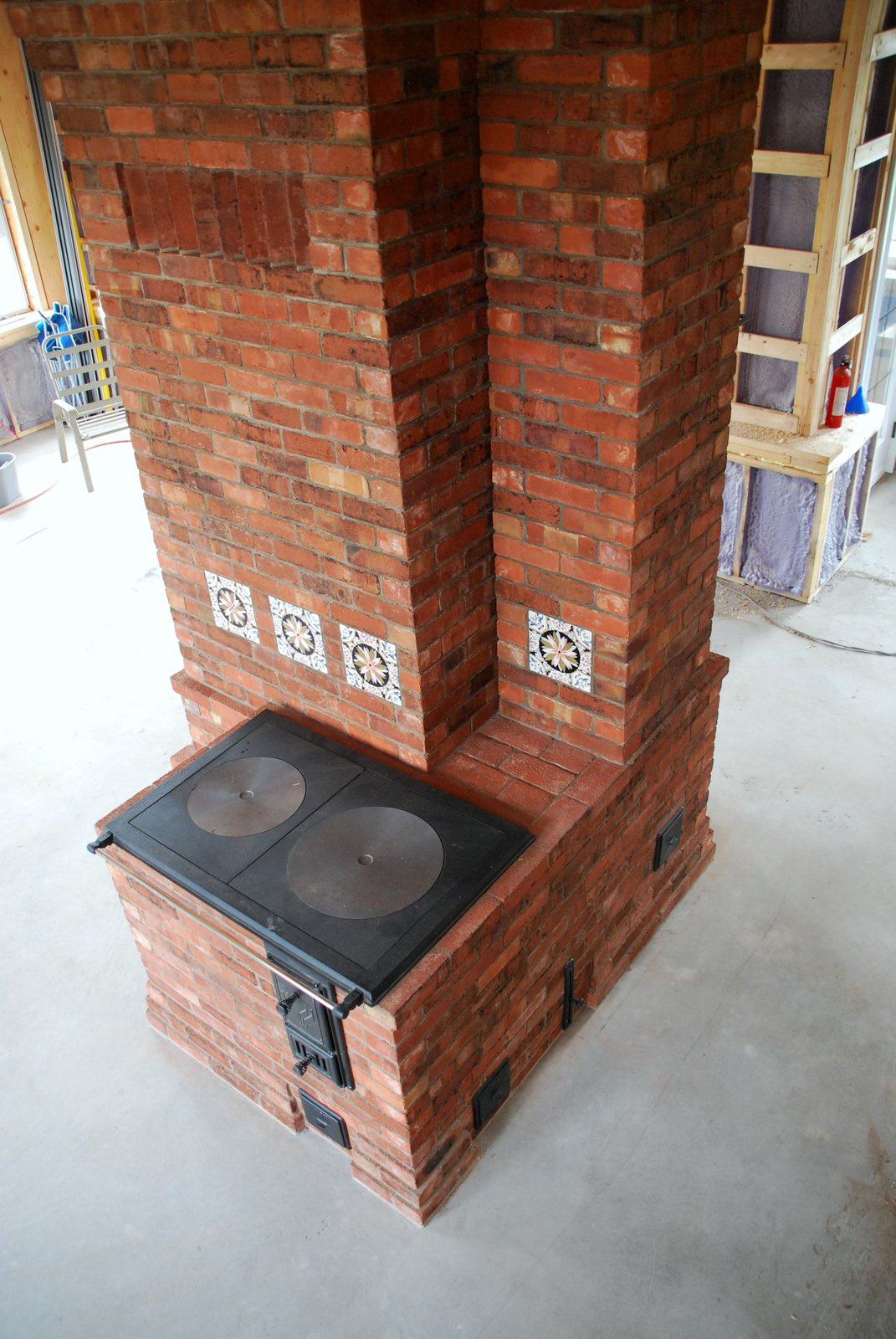
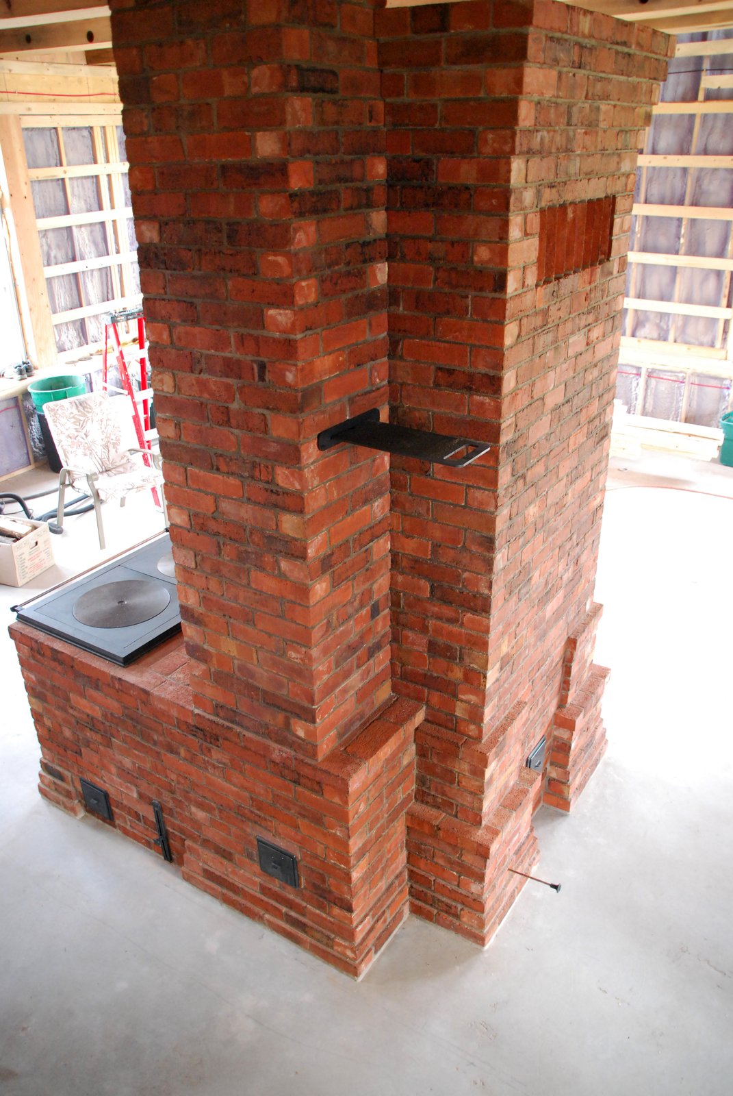
Two images of a similar cookstove which share the same flue as a contra-flow heater. Note the two pull rods of the dampers at 8 inches from the floor. The heater and cookstove can, in this case, be used at the same time.
The cookstove detailed below.
Both the heater and cookstove have an independent 9 inch round flue within a common chimney.
Materials:
The lower portion of the core will be of medium duty refractory brick layed in refractory mortar, the fire box and upper portions in high duty refractory brick layed in refractory mortar.
The facing will be of medium duty refractory brick layed in type N mortar.
450g glass fiber mat is used for gasketing.
The hardware is by Pisla Oy of Finland.
Note 1: The lower portions of the core and the facing would normally be in clay brick layed in refractory mortar and type N mortar respectively, though in this case, a variety of refractory products were available locally and surprisingly cost effective.
Note 2: Originally most European cookstoves were built from clay brick layed in clay mortar, with much of the stove being single skinned.
Note 3 : Unlike the masonry heater, the facing of the cookstove is usually layed up first, the core then being layed inside of the facing from above.
View
Cookstove Construction Sequence
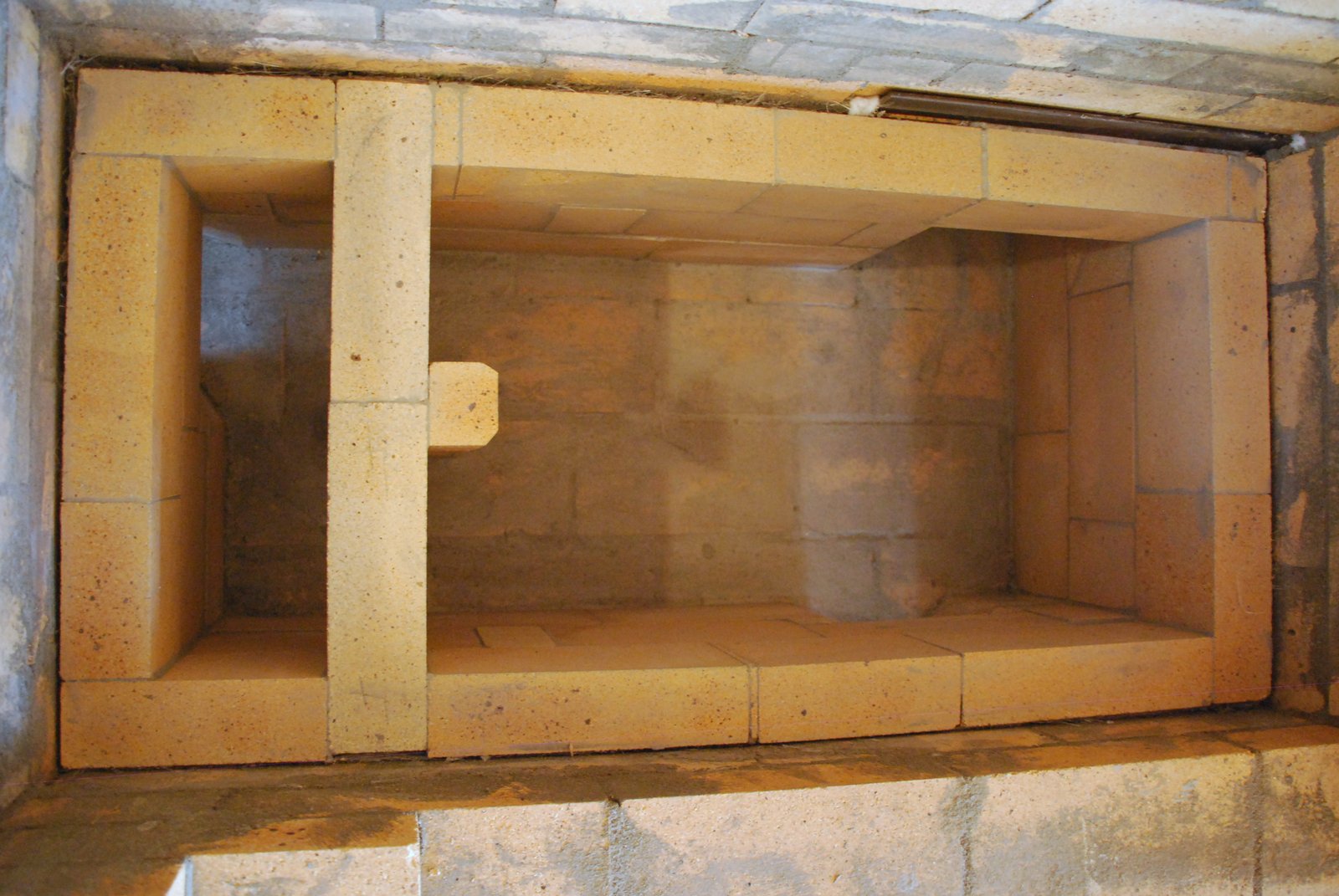
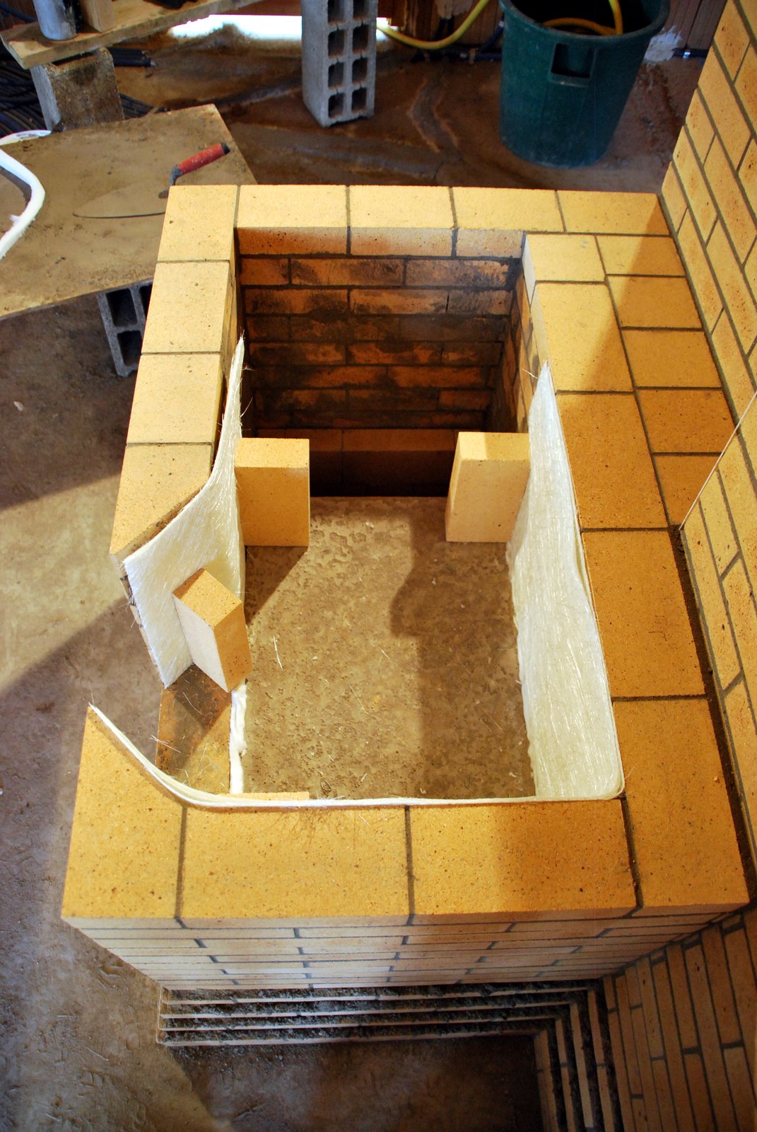
After laying approximately half the courses of the facing, the ‘bell’ chamber is built with shiners. A gasket of two sheets of glass mat is used between the shiners and facing. Three courses of shiners are layed leaving space for two shiners, in the second course, that will bridge, and lower, the ‘in’ opening of the chamber by resting upon the vertical support column
The ‘out’ opening into the chimney connection is also bridged at course two to lower the hight of the opening. The facing bridges the chimney connection using an angle bar lintel visible at the top of the image
NOTE: The curved form in the chimney connection is a plastic sheet protecting the base of the flue from fallen squeeze out.
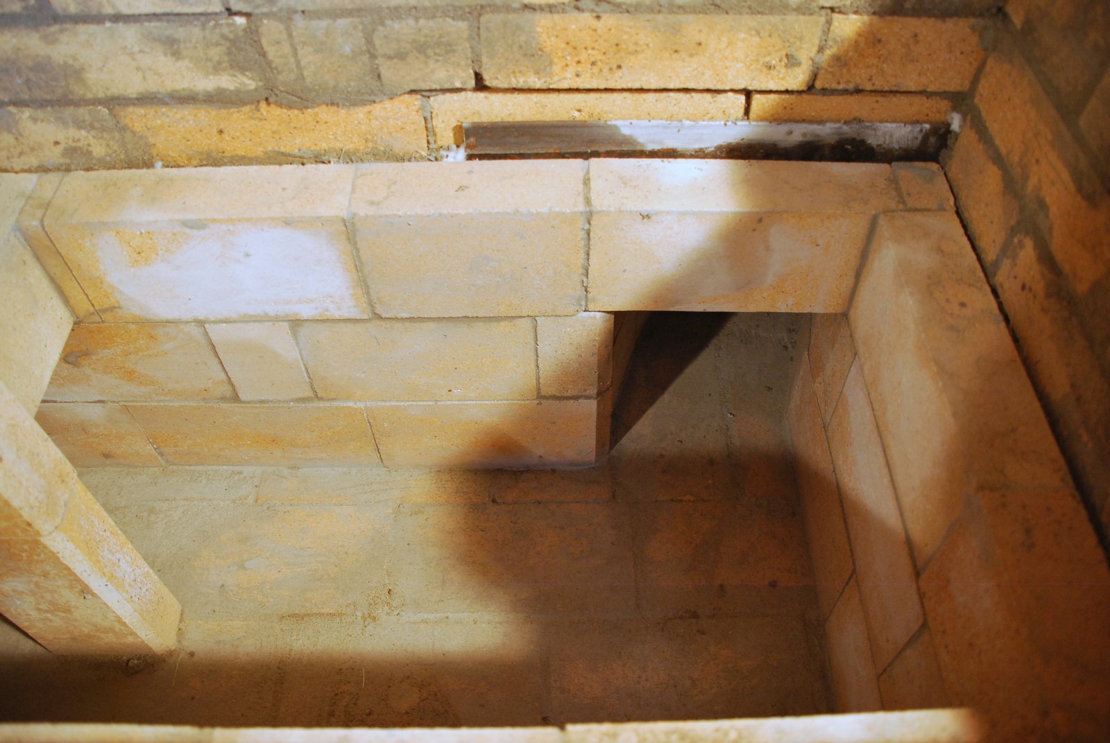
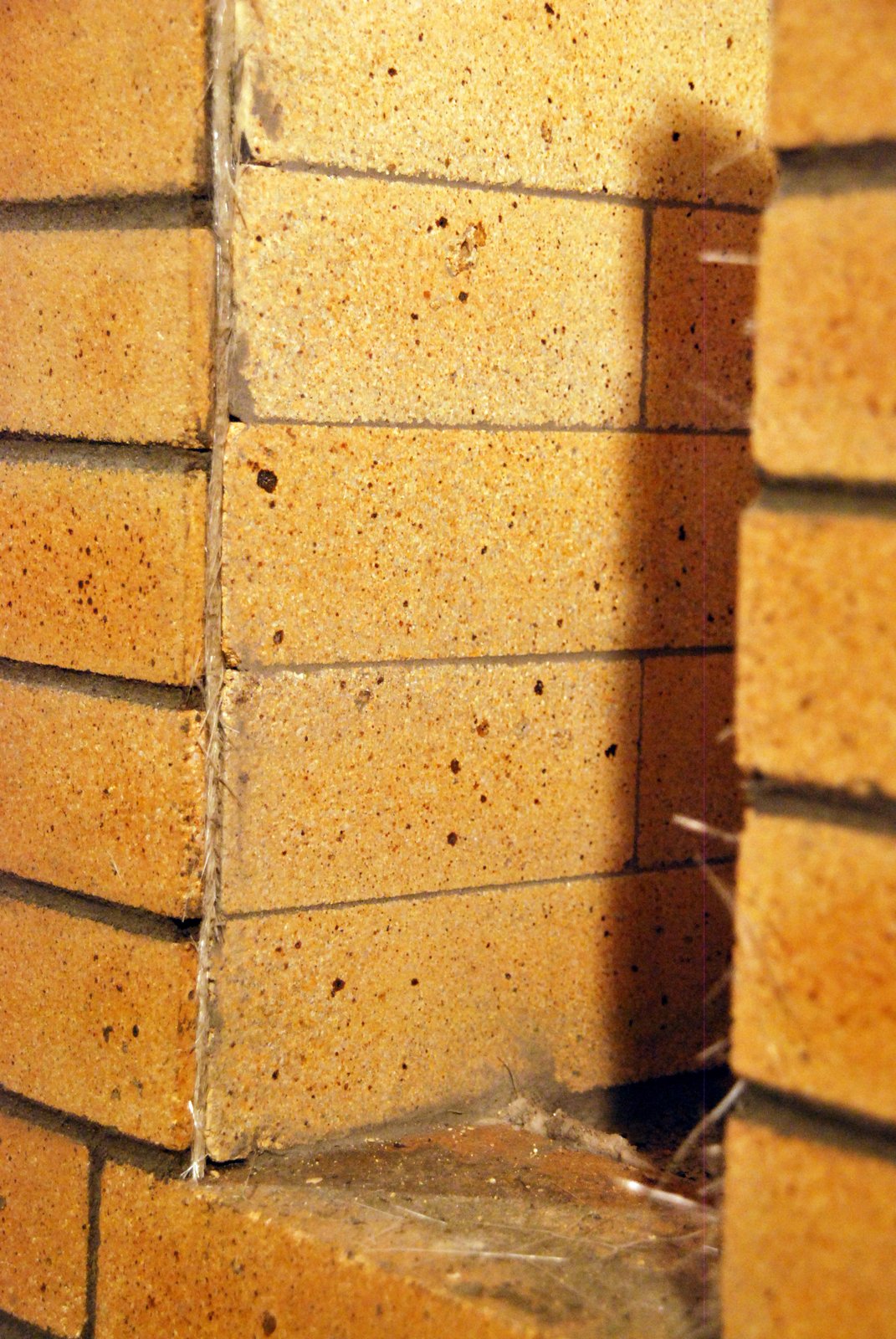
The ‘out’ opening from the bell bridged by a single brick.
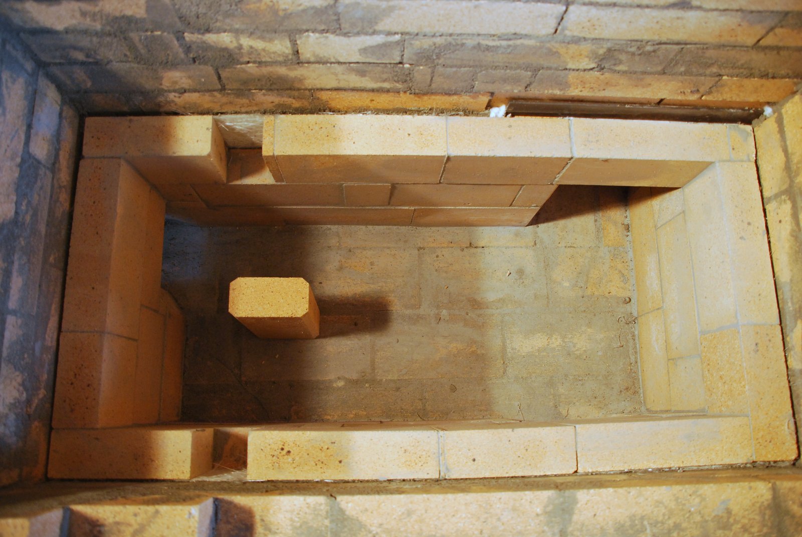
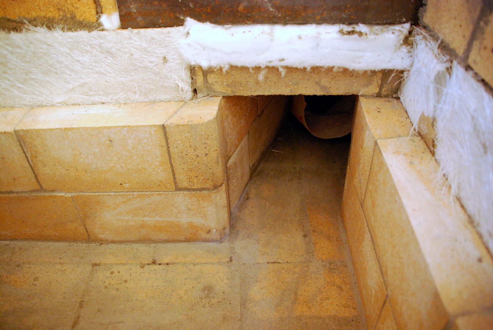
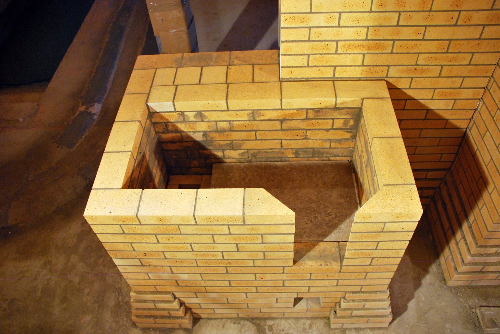
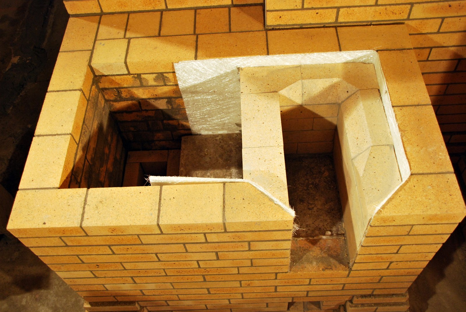
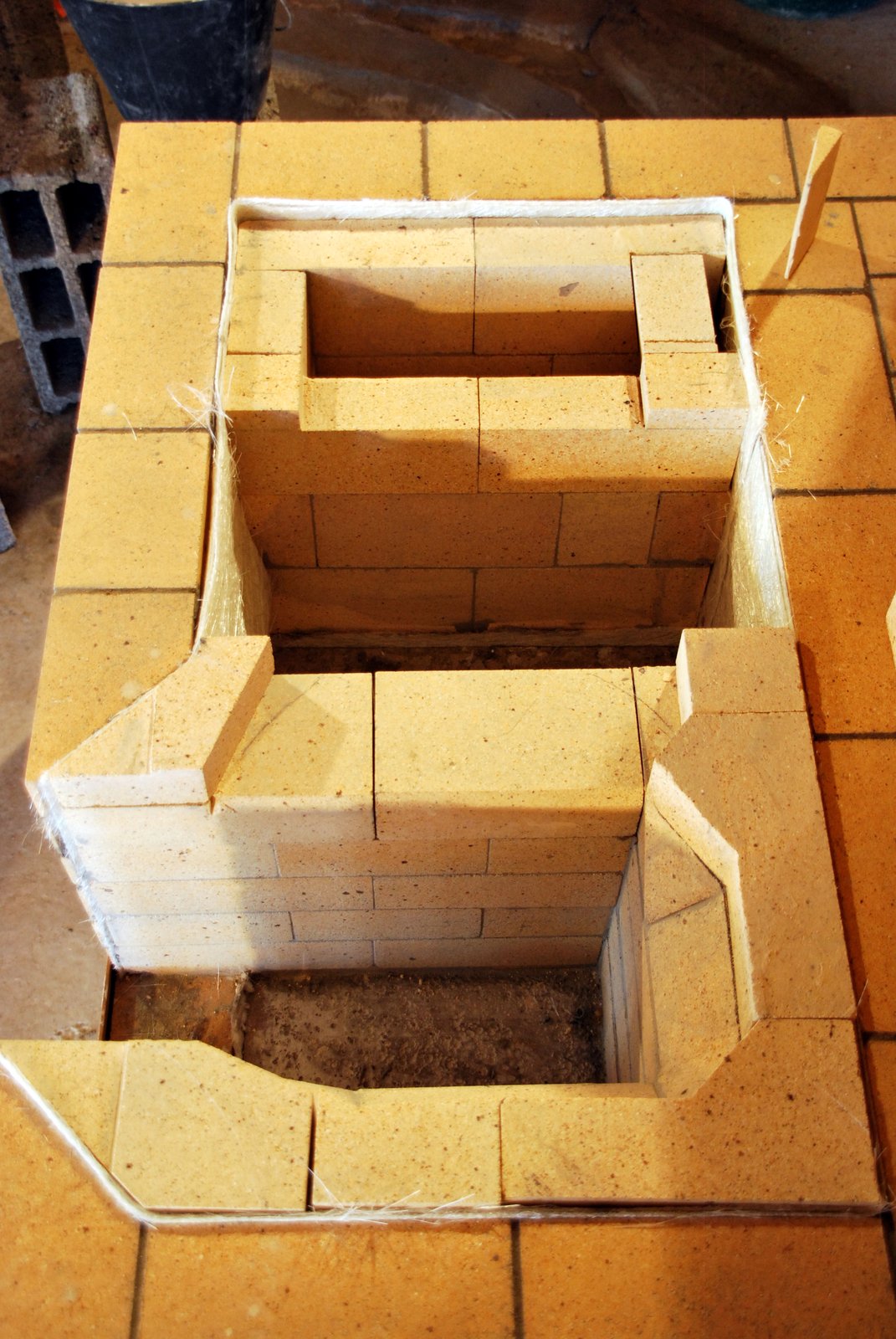
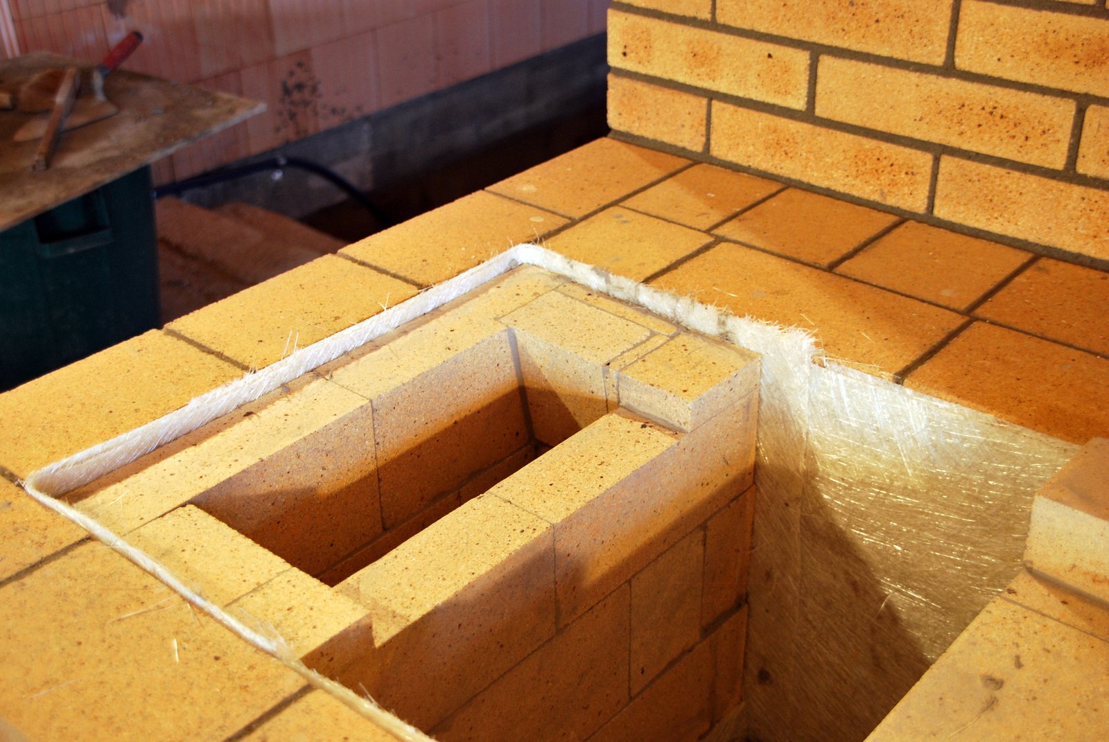
The three courses of the bottom of the down channel, at left, and the bell. The ‘out’ opening from the bell is is at top right, one access opening to the bell at bottom right, and a second access opening through the down channel to the bell at top left.
View along the bell towards the ‘in’ openings from the down channel. The ‘out’ opening to the chimney connection is at bottom right, the access opening into the bell at bottom left. The ‘in’ openings to the bell from the down channel at top, and beyond the down channel the second access opening at top right.
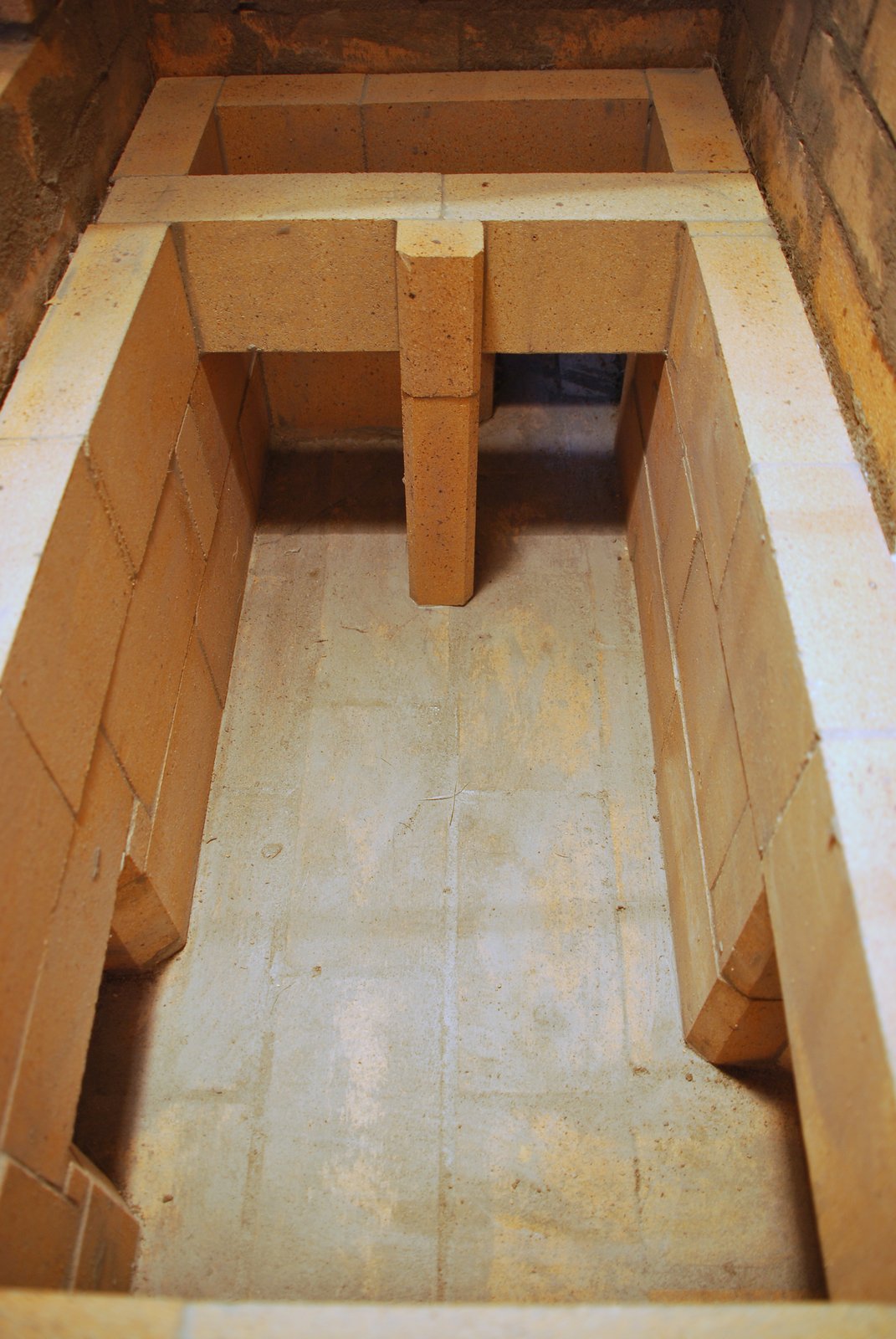
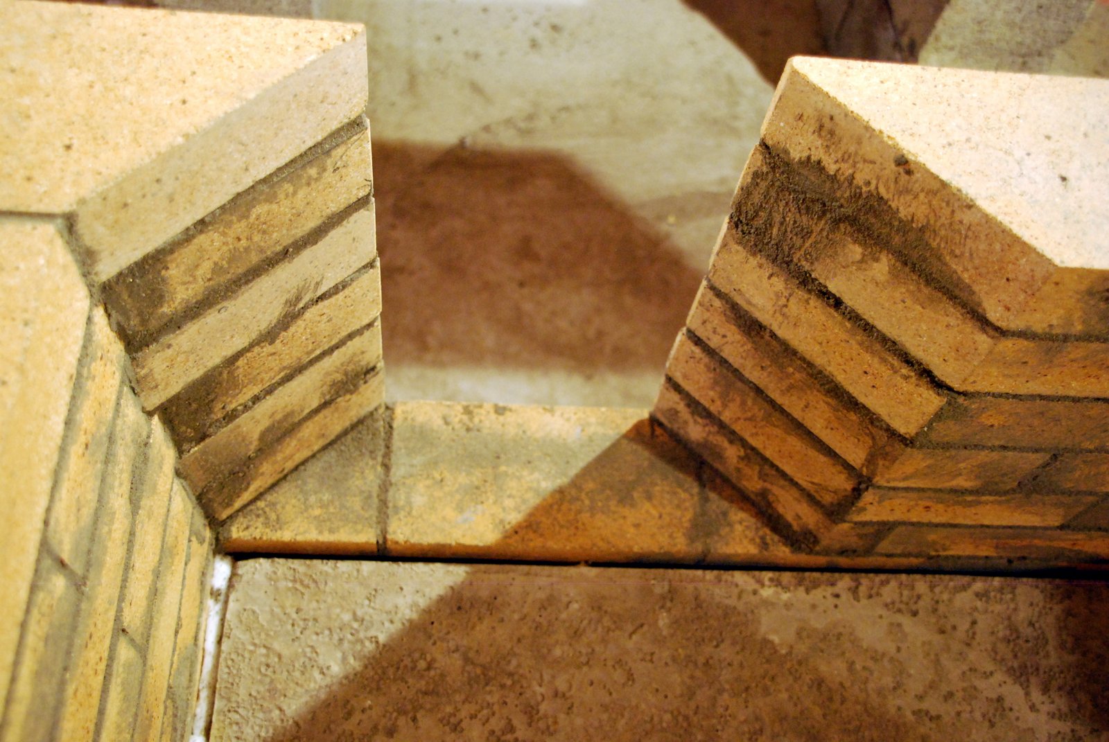
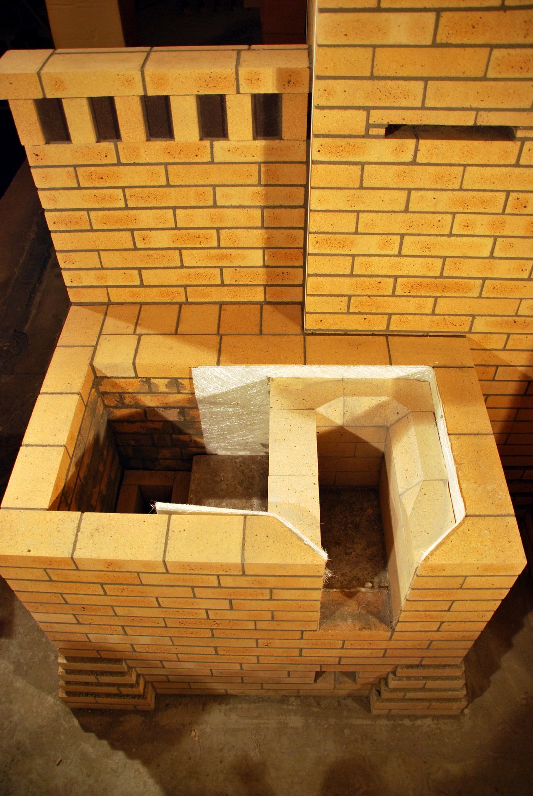
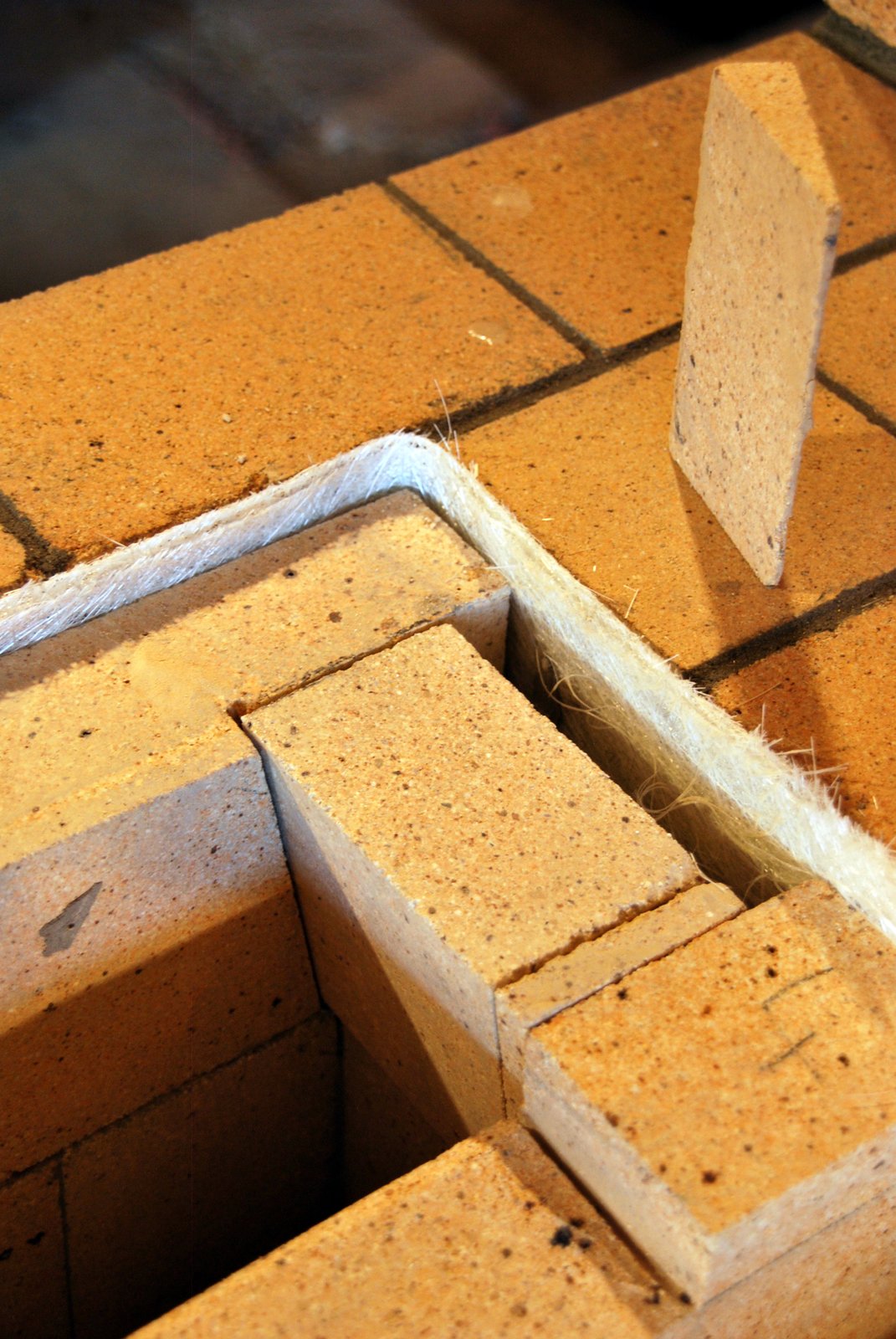
An extension to the support column behind the two bricks bridging the ‘in’ opening will support the closure slab of the bell.
Note: From the two access openings the entire inner surface of the chamber can be touched by hand .
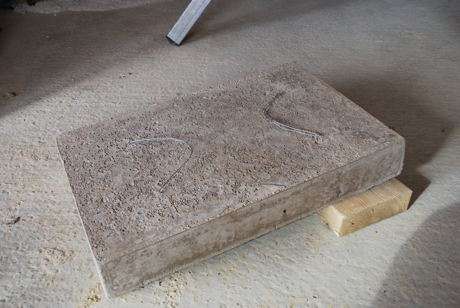
The bell is closed by a capping slab poured in dense castable refractory concrete.
During pouring 4 wire eyelets are inserted into the slab, which will assist the slab being lowered into position.
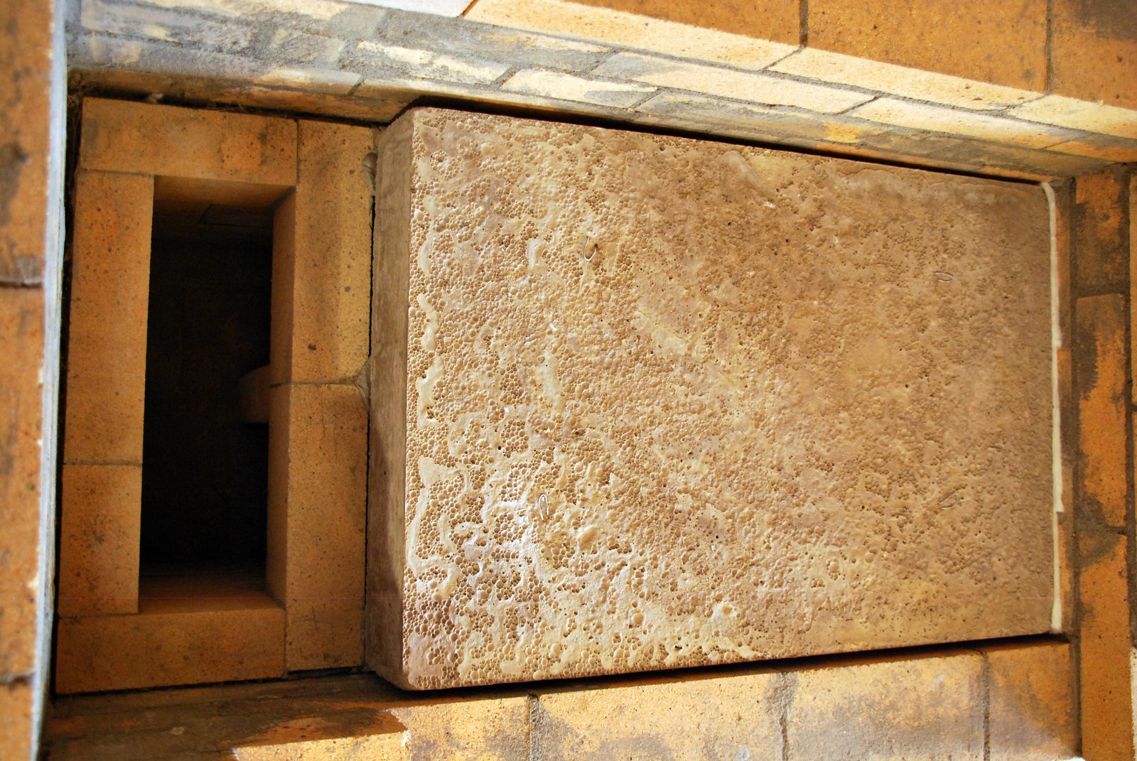
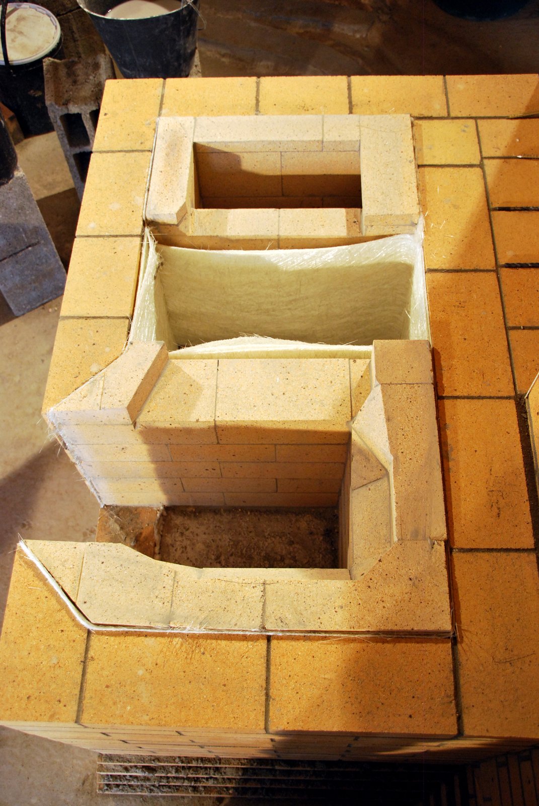
The bell closed by its slab. The slab rests upon the three walls of the bell chamber, top , bottom, and right, and the extension to the support pillar to the left. The slab is lowered onto a bed of refractory mortar spread onto the upper surfaces of the chambers walls and support pillar.
The slab is cast slightly smaller than the walls of the bell to allow the insertion of a glass fiber gasket.
The walls of the down channel are to the left of the capping slab.
A cardboard template is made to the outer dimensions of the cook top , and the dimensions of the inner frame, plus the precise location of the two hot plates. This avoids repeatedly lifting the elements of the cook top on and off the work during the lay out for the core .
The completed facing. The down channel will be layed up to the left and the fire box directly upon the capping slab to the right.
The skew cut facing brick around the fire box loading opening. Great care must be taken when executing this work as the loading opening is a point of potential weakness.
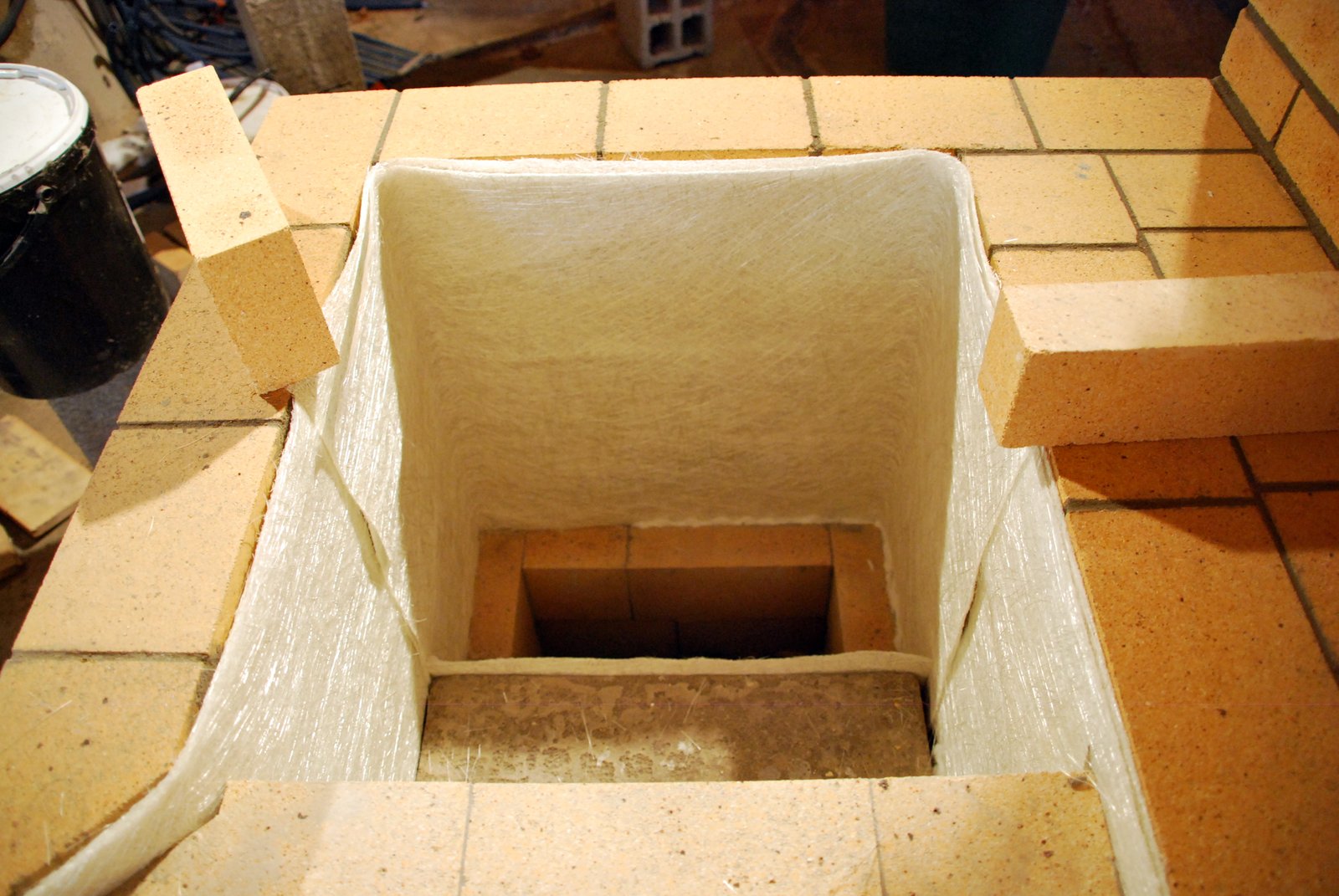
Before laying the fire box the inner surface of the facing is gasketed with three sheets of glass mat . The gasket is held in place by being inserted into the empty joint between the capping slab and the facing. This joint is filled with ceramic wool at the loading opening.
Five of the 6 courses of the fire box. The brick forming the left and rear wall are whole, with those of the right wall being cut back slightly, i.e. aprox 1cm cut from the width, to accomodate the format of the facing brick.
The left side of the skew cut fire box wall as it intersects the skew cut facing brick of the loading opening. When the fire box door is installed the inner flange will protrude 3 cm into the opening, more than covering and protecting the area seen here.
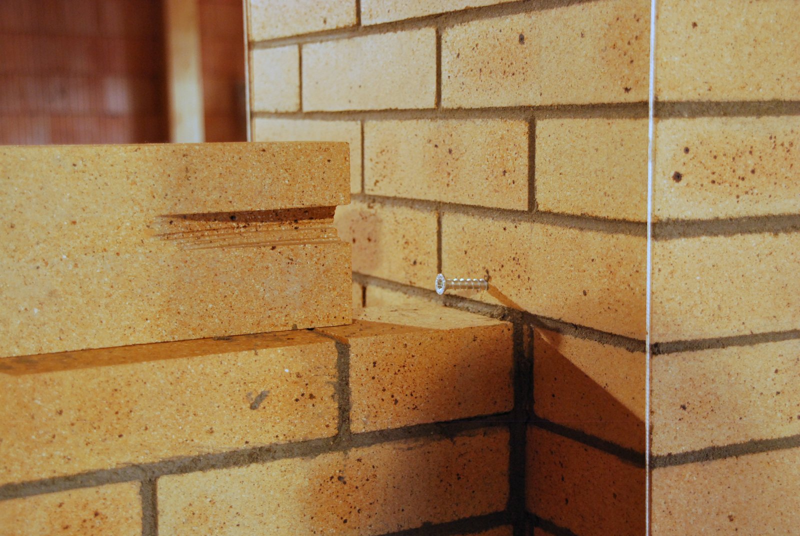
General view with the splashback.
The single wythe splash back behind the cookstove is anchored to the chimney with a masonry screw, rather than being bonded.
Two sheets of glass mat are used to gasket the down channel.
The completed down channel and fire box, with the sixth course of the fire box layed dry before being mortared in place. This last row of the fire box is cut to within 5mm of the lower surface of the cook top to avoid flame bite on the portions of the cook top other than the hot plates.
The down channel is also layed up to within 5mm of the cook top, its wall to the right being sloped inwards, also to keep the stream directly below the second hot plate and away from the surrounding frame.
Detail of the reduction in width of the wall of the down channel.
The completed down channel.
The gasketing of the void between the down channel and the fire box. This void is filled with scrap before being brought up to the overflow level of the fire box and down channel, with refractory brick.
Critiqe by A Chernov: The void could also be incorporated in to the bell rather than being filled.
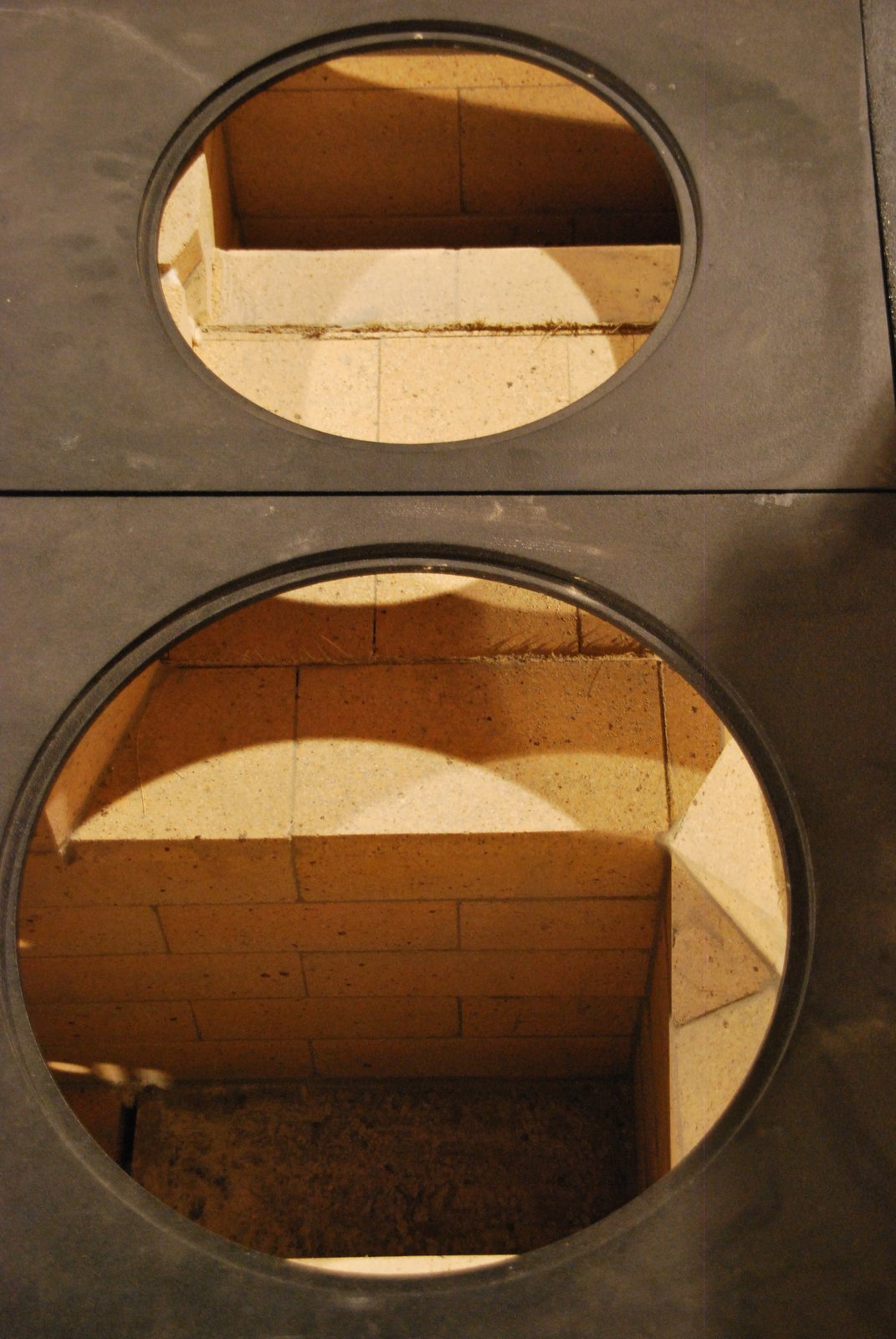
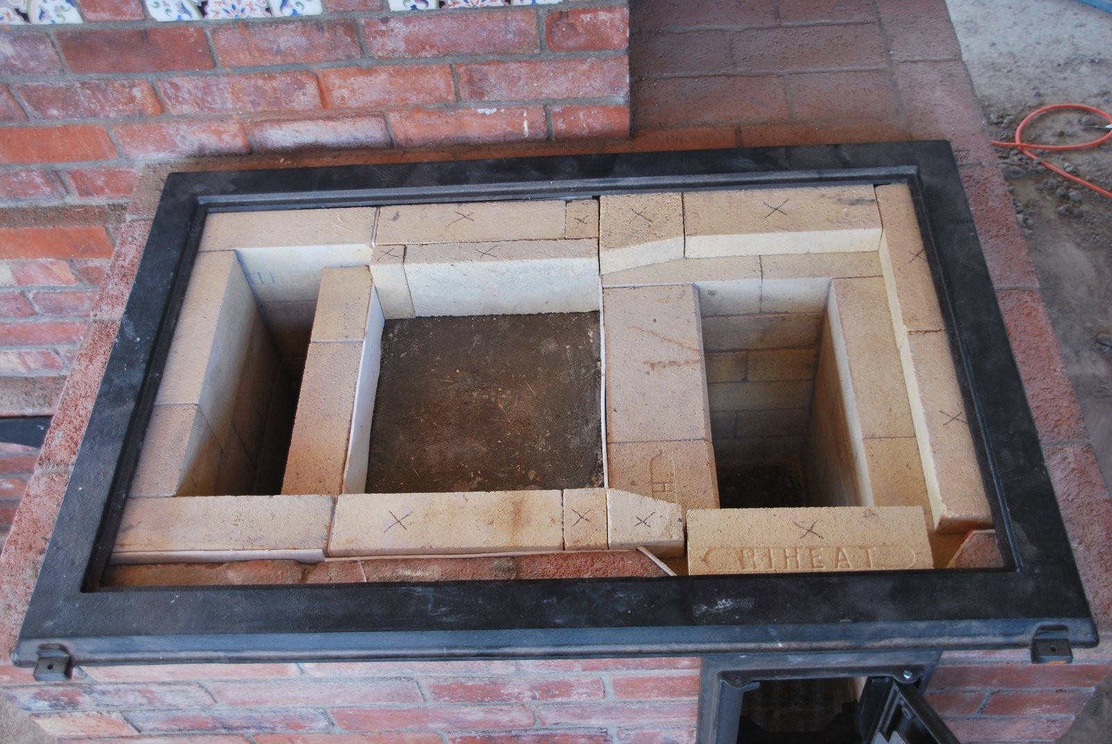
The smoke path running directly beneath the two hot plates, the other portions of the cast iron cooktop being almost entirely shielded from the stream.
The over-flow, or inner, surface of the smoke path is 4cm below the heat exchange fins of the hot plates.
For comparison: The last course of the stove illustrated in the first two images. The brick that will fill the void and bring it to level have yet to be layed. All the pieces of brick marked with an x are completely free floating and act primarily as heat shields.
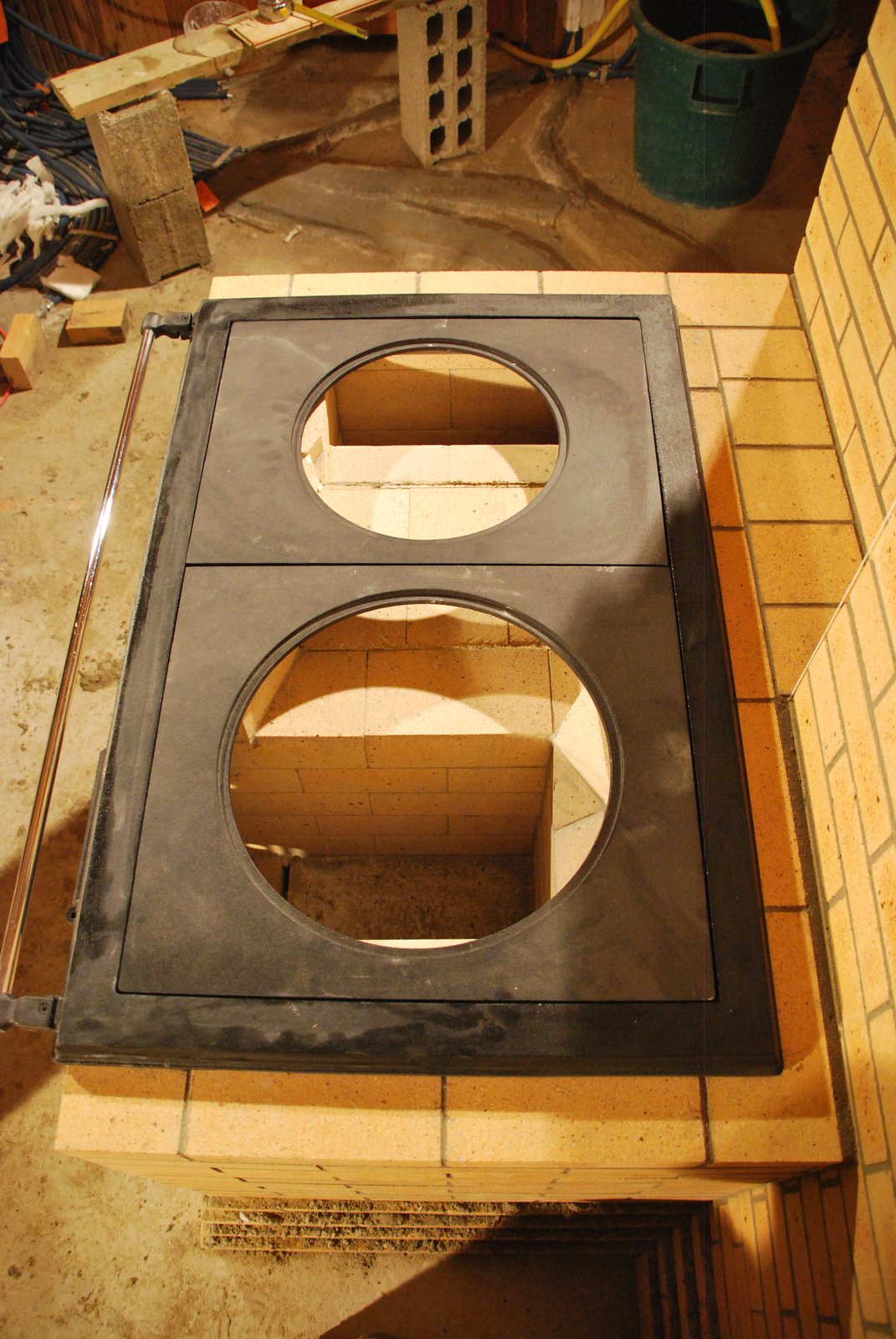
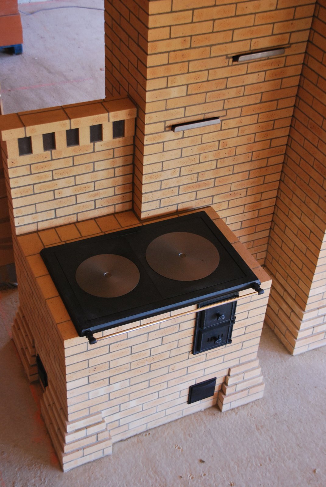
The completed stove. A guillotine damper in its own independent chimney flue (the lower left of the two dampers) is used to regulate the draw and close off the flue when the stove is not in use.