Cookstove Construction Sequence
Detailed is the construction of a custom built cookstove in the Lorentian Shield Quebec.
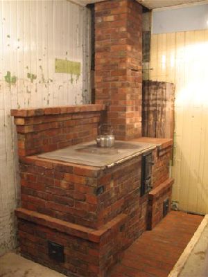
The objective was to build a simple, robust, all seasons, variation of the traditional Finnish cookstove
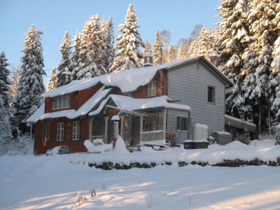
The dwelling was an extended log construction dating from the 1830s. Newly occupied and under renovation. A contraflow masonry heater would act as the principal heat source.
The intention of the home owner is to burn only soft wood on both the heater and cookstove.
MATERIALS
Refractory Brick
Mount Savage High Heat
Refractory Mortar
Mount Savage Super High Mullite
Ceramic Wool
Vesuvius HP6
Facing Brick
Recycled High Density. Burnt Clay
Flue Liner
Burnt Clay
Hardware
Upo
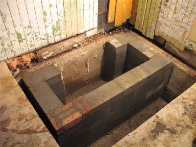
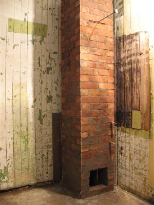
After pouring a suitable footing an elevated forundation is built. The reinforced concrete foundation pad will rest on the block and also on the existing foundation wall of the house, to the right and behind.
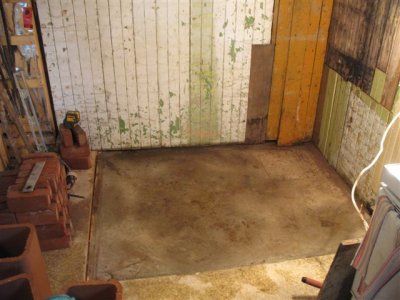
The slab is poured to ½ inch below the sub-floor.
The chimney will be built before the cookstove due to the pending onset of winter.
The 8 x 8 inch flue liner is cut to accept a section of tile of the same format.
The 8 x 8 inch flue liner is cut to accept a section of tile of the same format.
At 6 feet a cast iron shut off damper is installed.
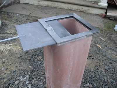
The damper consists of two cast iron frame plates, a guillotine plate and operating handle.
The damper consists of two cast iron frame plates, a guillotine plate and operating handle.
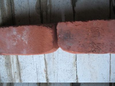
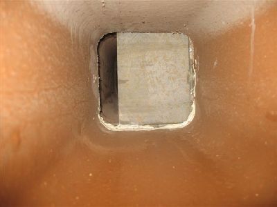
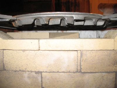
Seen from the side, the flue tile has been marked and cut down to exactly the level of the last course of brick.
The groove on the top of the right side of the tile is to accommodate the bulge in the frame plates, where the handle passes through the plates. The tile inserted above the damper will also be grooved, on the face that contacts the damper frame.
The outside corners of the tile are grouted against the brick. This is in order to hold the tile in position at the point of regular lateral stress from the operation of the damper.

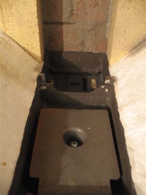
The lower frame plate is layed directly onto the tile with refractory mortar. In this case Duchasnes HTC which is white.
The upper plate is placed in position and of ceramic wool wrapped around the edge of the damper frame.
The dampers handle and plate will pull directly out of a bed joint. This avoids cutting of any brick.
The wooden shims are inserted into the damper until they are approximately the thickness of a joint. They will support the brick until sufficient courses have been layed above for them to be taken out.
The wooden shims are inserted into the damper until they are approximately the thickness of a joint. They will support the brick until sufficient courses have been layed above for them to be taken out.
The corners of the rear faces of the two brick layed on to the wooden shims are rounded to prevent the angular bulge in the guillotine plate where the handle is attached, from catching on the brick as the damper is operated. This is quite an important consideration
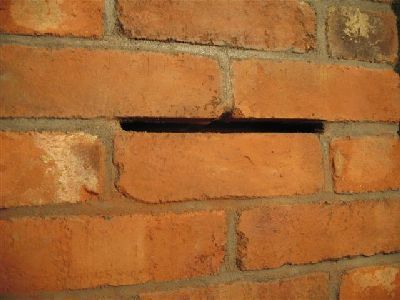
The empty joint into which is inserted the guillotine plate.
It is worth taking the time to do this with precision to avoid the necessity of a cover plate.
The tile above the damper is also layed directly on to the plate in HTC.
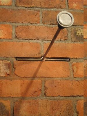
View down the flue to wards the damper guillotine plate. Three quarters closed.
Brick ties are inserted to tie in the surrounding cookstove.
If the cookstove and chimney had been built at the same time it would not have been tied in to the chimney ,other than with ties as seen here.
If the cookstove and chimney had been built at the same time it would not have been tied in to the chimney ,other than with ties as seen here.
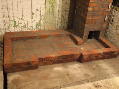
The first course of clay brick dictates the footprint of the cookstove.
There is 4 inches of clearance between the rear and side faces of the stove and the combustible walls.
There is 4 inches of clearance between the rear and side faces of the stove and the combustible walls.
Several courses of brick are layed before the construction of the lower flue way. All the common clay facing brick in this stove are layed in type N mortar.
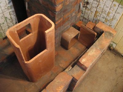
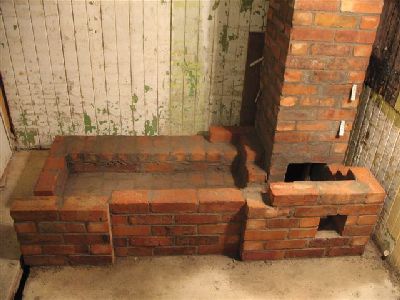
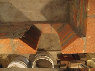
A section of 8x8 inch flue is used to connect the chimney flue to the lower channel which is made from two 8x12 inch tiles.
Note the rectangular piece of tile that will close the end of the lower channel at the chimney connection
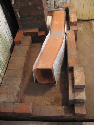
The flue tiles layed in place, are gasketed with fiber glass mat before building up the masonry around them.
The traditional zigzag narrow lower smoke path of the Finnish cookstove has not been built here as a primary objective of the stove is to have a strong draw in all seasons. The flue is made with 8x 12 inch tiles to maximise surface area and so captivation.
The traditional zigzag narrow lower smoke path of the Finnish cookstove has not been built here as a primary objective of the stove is to have a strong draw in all seasons. The flue is made with 8x 12 inch tiles to maximise surface area and so captivation.
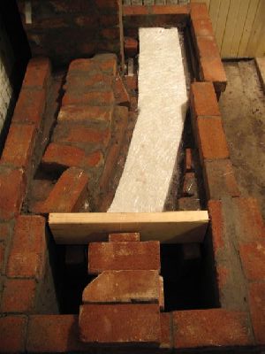
The upper surfaces of the flue tiles are gasketed with two leaves of fiber glass mat before pouring with common concrete.
The concrete will contact the masonry each side of the flue, though not actually exert any force on the flue tiles , which are free floating.
The concrete will contact the masonry each side of the flue, though not actually exert any force on the flue tiles , which are free floating.

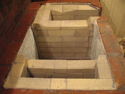
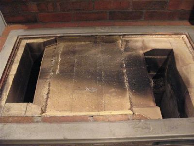
At this point the vertical down channel seen here should be lined with fire brick shiners, while it is still accessible.
View along the lower flue towards the chimney connection.
After gasketing with fiberglass mat the down channel is lined with firebrick shiners.
Two leaves of mat were used on the ends and a single leaf on the sides.
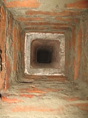
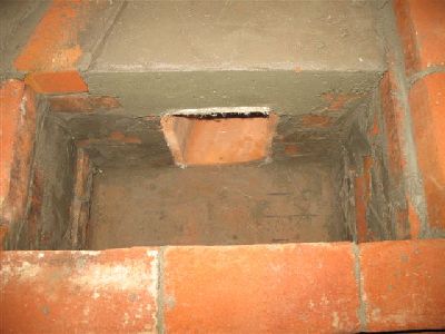
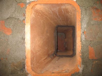
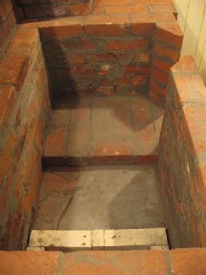
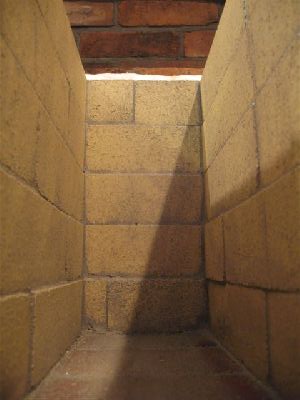
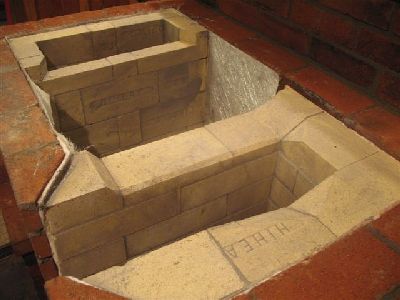
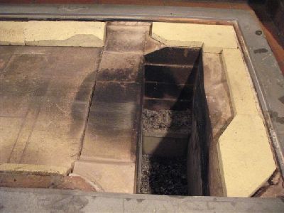
View towards the bottom of the down channel.
The opening at the top (of image) is the flue access opening.
At bottom is the flue entrance which has been restricted to 6 x 6 inches to be equal to the capacity of the 6 x 6 (interior dimension) flue tile used in the chimney connection.
The use of 4 feet of 8 x 12 tile between these two points is an attempt to maximise recovery from the smoke steam with out forcing it through a narrow twisting smoke path.
Note; In North America clay flue tiles are listed by there exterior dimensions The two formats used in these notes are 8 x 8 inch and 8 x 12 inch . The internal dimension, and so actual capacity of the tiles is 6 x 6 and 6 x 10 respectively,
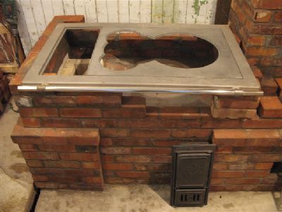
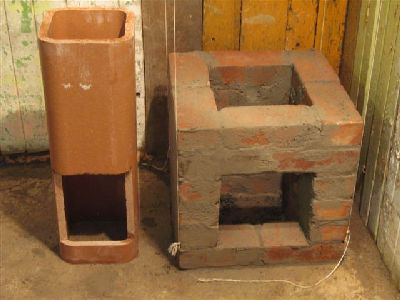
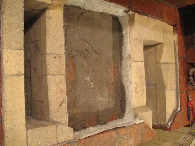
At this point the outer and inner frame of the cook top are layed in place in order to locate the fire box loading opening in relation to the position of the first hot plate.
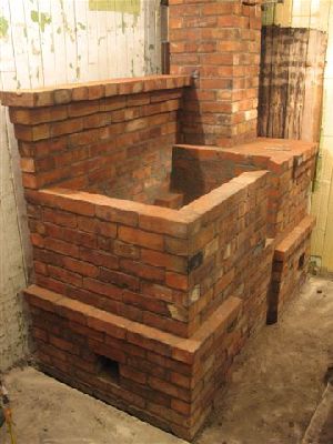
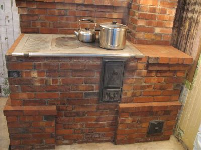
All the facing work is finished, along with the splash back.
The actual rear wall of the cookstove is not yet built. There being at this point only the single wythe wall of the splash back. When the rear wall of the cookstove is layed up there will be two full solid wythes of clay brick behind the 4½ inch refractory brick wall of the fire box.
The actual rear wall of the cookstove is not yet built. There being at this point only the single wythe wall of the splash back. When the rear wall of the cookstove is layed up there will be two full solid wythes of clay brick behind the 4½ inch refractory brick wall of the fire box.
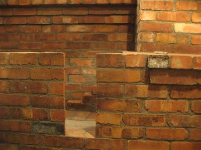
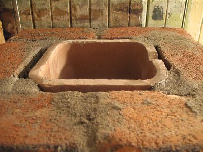
The fire box loading opening.
View of the fire box loading opening from above. The brick forming the opening are cut back to allow the skew cut fire brick of the fire box walls to protrude behind the flange of the loading door.
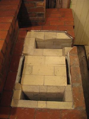
The rear wall of the cookstove is layed up.
A course of clay brick is layed beneath the fire box to bring it up to height.
A course of clay brick is layed beneath the fire box to bring it up to height.
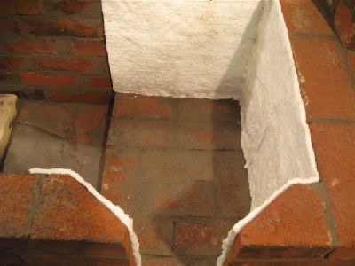
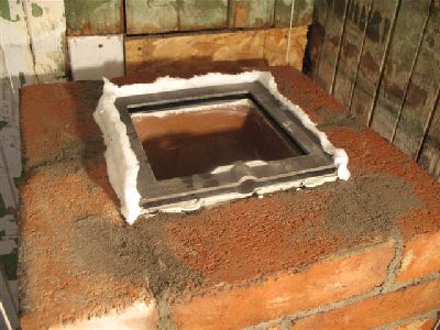
Before starting to build the fire box the masonry against which it will rest is gasketed with ceramic wool. Here, half inch sheets of wool are manually torn it to two equal halves .
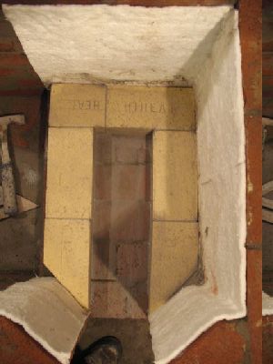
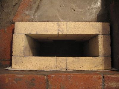
The first course of the fire box.
Once the first row of the fire box wall is layed, the door is temporarily inserted.
The opening is 3/16 inch larger than the with of the door flange.
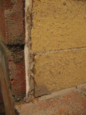
The skew cut brick of the fire box wall completely shield the facing brick. The mineral wool gasket accommodates any lateral expansion of the fire box towards the facing.
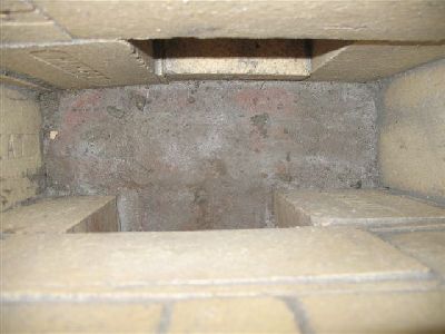
The second to last course of the fire box.
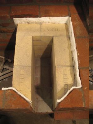
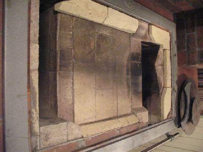
View into the fire box.
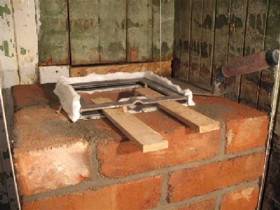
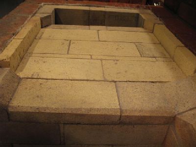
The last course of the fire box is cut to form and layed dry. The inner and outer frame of the cook top along with the large hot plate are placed into position to accurately control the height of the outflow between the top of the fire box wall and the bottom of the large plate. If this space is too big then the smoke stream will be low, and barely contact the heat exchange fins of the large plate. If the fire box wall at the out flow is too high then the smoke stream will wash against the inner frame of the cooktop which could fail, as it is designed to remain relatively cool.
Here there is 1 3/4 inches between the bottom of heat exchange fins and the top of the fire box wall. Once assessed the dry layed brick are mortared in to place.
Here there is 1 3/4 inches between the bottom of heat exchange fins and the top of the fire box wall. Once assessed the dry layed brick are mortared in to place.
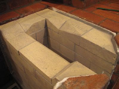
The last row of the fire box walls. The angled recess cut into the inside top edges of the right and rear walls are to accommodate the peripheral heart exchange fins of the large hot plate.
The height of the fire box wall at the out flow and the inner wall of the down channel are the same.
The void between the fire box and down channel is gasketed with 2 leaves of glass fiber mat.
Clay brick are layed in the void leaving room for 1 course of refractory brick.
Refractory brick are layed to the height of the inner walls of the fire box and down channel. Room is left on each side to insert a refractory brick split.
The two rows of splits shield the facing. They are free floating and can be easily removed.
The cooktop frame is layed on to a thin bed of type N mortar, and a small priming fire lit.
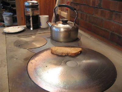
During the first fires it was noticed that the rear of the two small plates, was getting hotter than the closer one.
On removal of the inner frame and plates, smoke path could be clearly seen to run diagonally beneath the plate.
On removal of the inner frame and plates, smoke path could be clearly seen to run diagonally beneath the plate.
These final dry layed pieces are easily changed or adjusted. If layed in refractory mortar they would probably break loose.
Pieces of refractory brick were cut to shape and dry layed into the smoke path These pieces divert the smoke away from the back left corner and into the centre.
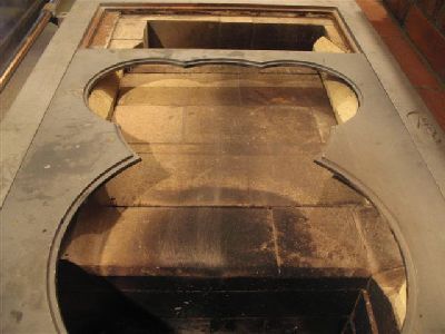
The smoke path is now centered beneath the hot plates.
Marcus Flynn
2009
