Chimney Connection #11
This article illustrates the connection of a contraflow heater and cookstove using two transmission tunnels, to a common remote single flue chimney.
Until the heater and cookstove are finished and fired it will not be certain that both will be able to be used at the same time without spillage. To be certain of this, each would have to be linked to a separate chimney flue. As the two will 'probably' draw simultaneously via the same flue it is worth the risk, to cut considerably on the extra expense and space needed for an additional flue.
Each stove will have its own shut off damper located in its transmission tunnel, and there will be a master damper in the chimney on the upper floor.
The chimney will consist of a 230 mm ID burnt clay flue, faced with common clay brick.
Materials:
Ceramic Blanket:
Superwool 607 HT 13 mm
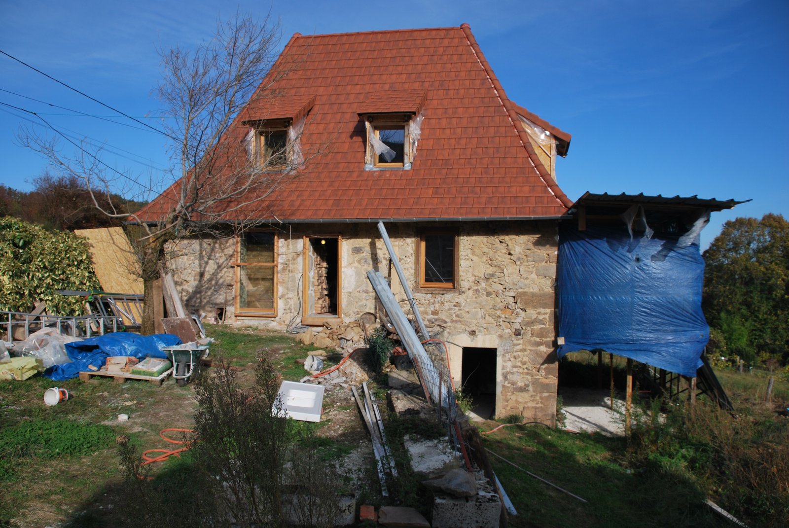
The Site. The building is about 3 centuries old. It will eventually be insulated from the exterior to preserve the inertia of its 70 cm thick masonry walls.
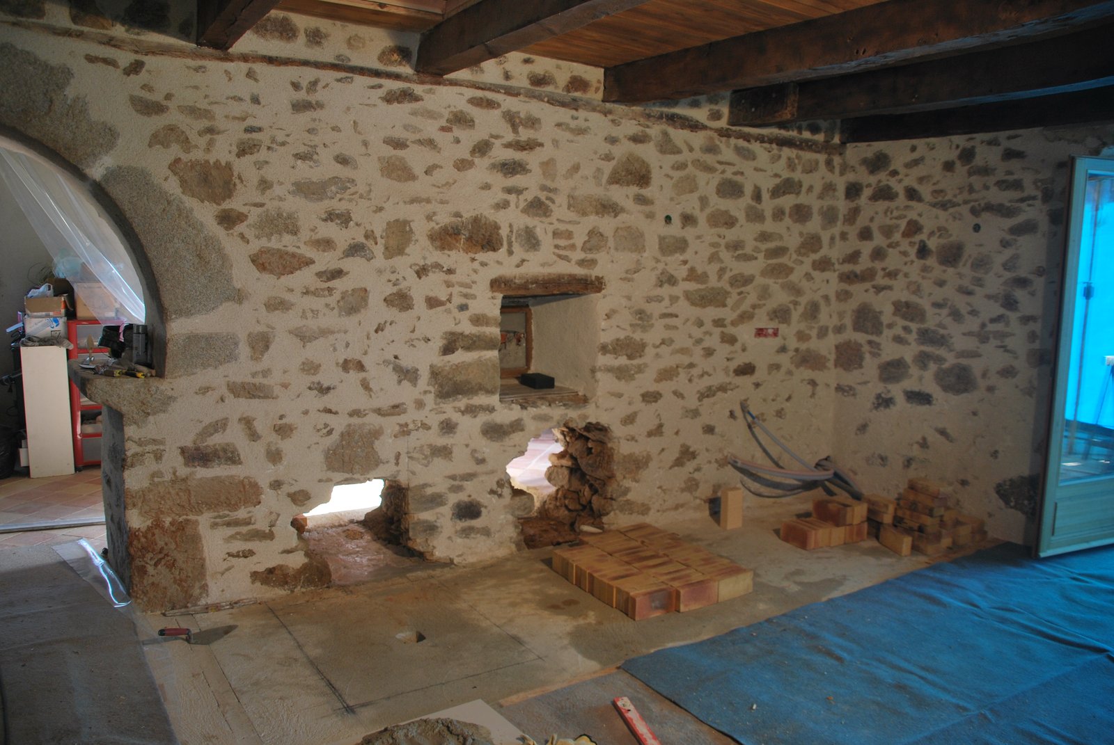
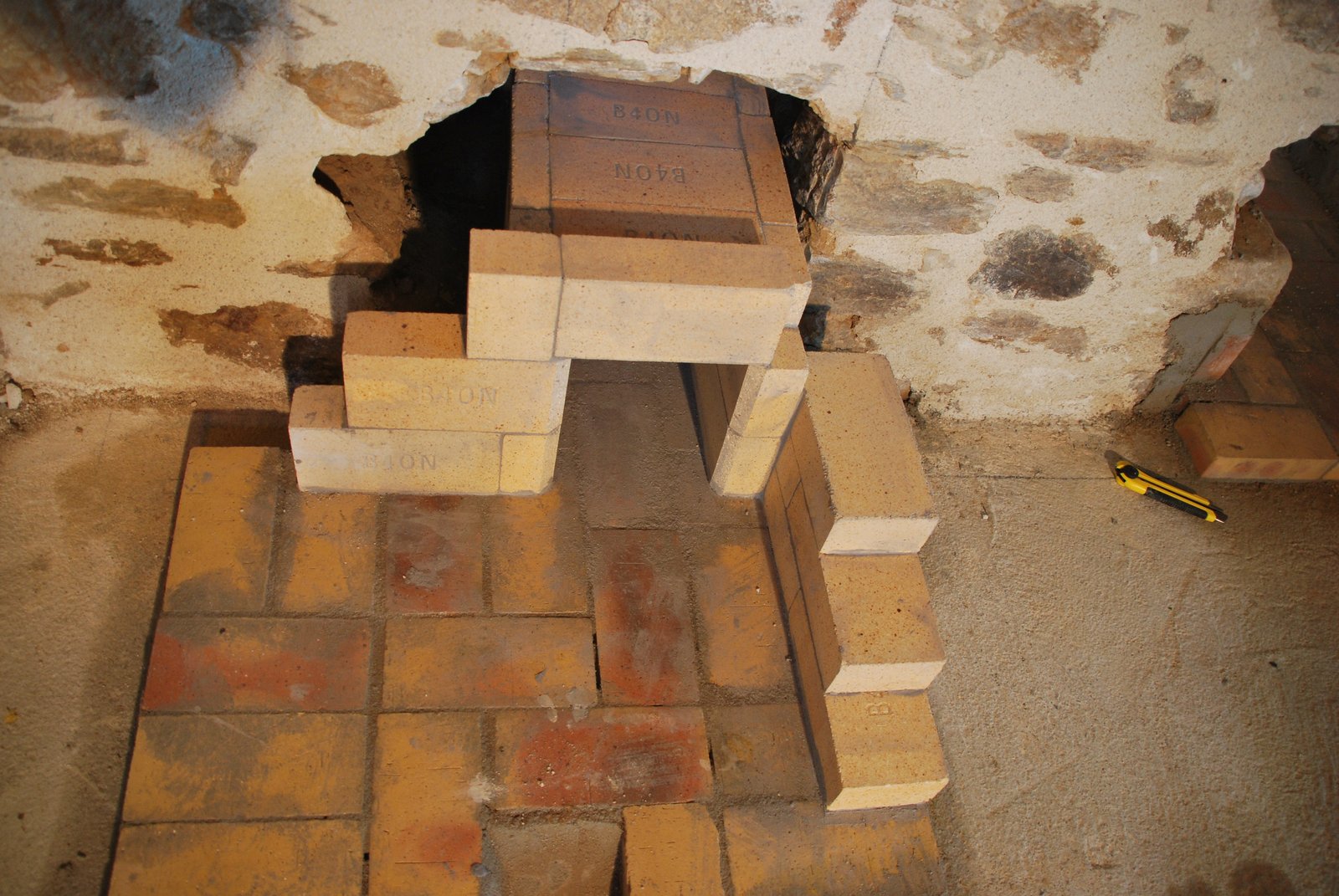
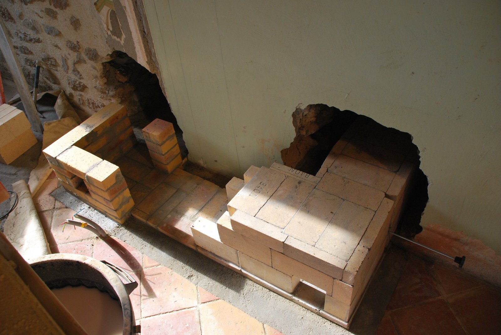
The living area. The two transmission tunnels from the heater at left, and the cookstove to its right, will pass through the two openings in the wall, to the chimney located in the room behind the wall.
A base course of common clay brick is layed through each of the openings.
The heaters transmission tunnel is connected to its side manifold at the juncture of it and the rear manifold. As both the heater and cookstove will be built against the wall, the transmission tunnels and their connections must be built first.
The shiner forming the lintel over the tunnels opening represents the line of the side channel wall. The three courses layed flat to the openings right, the rear manifold wall.
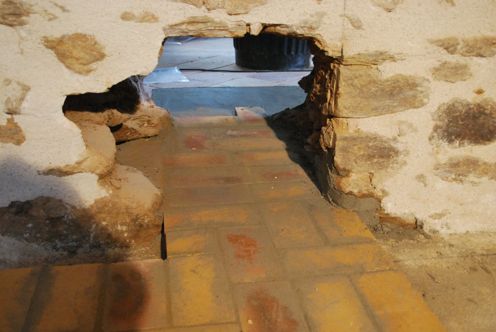
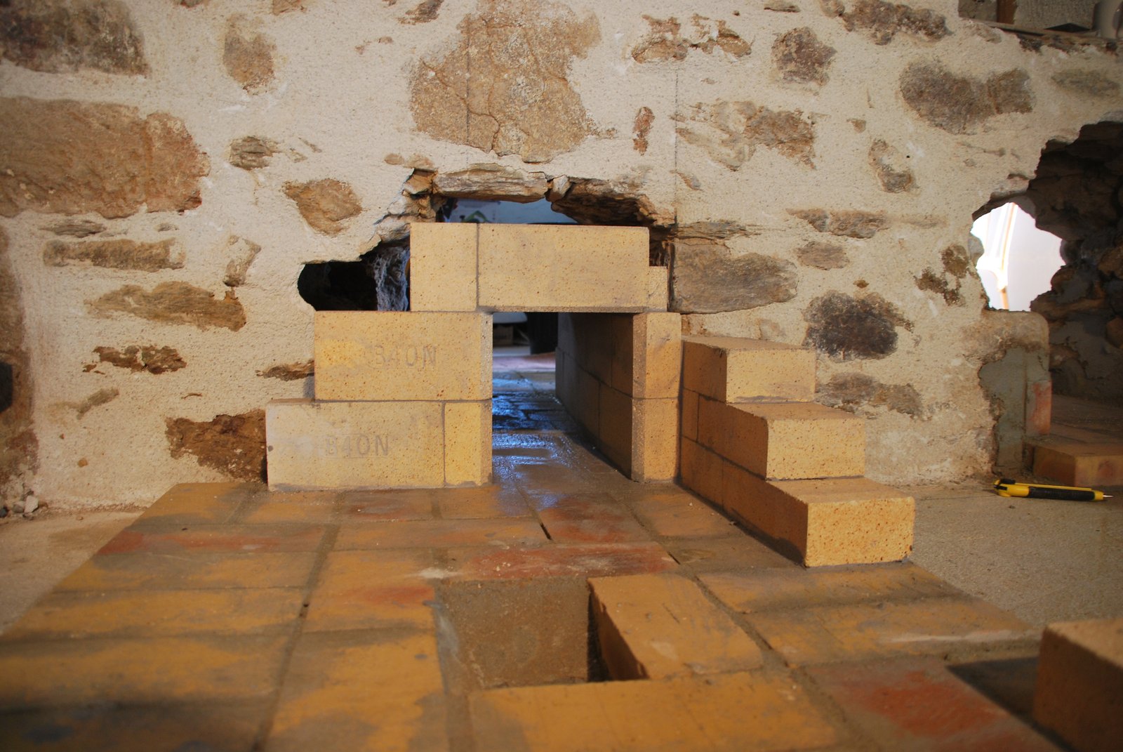
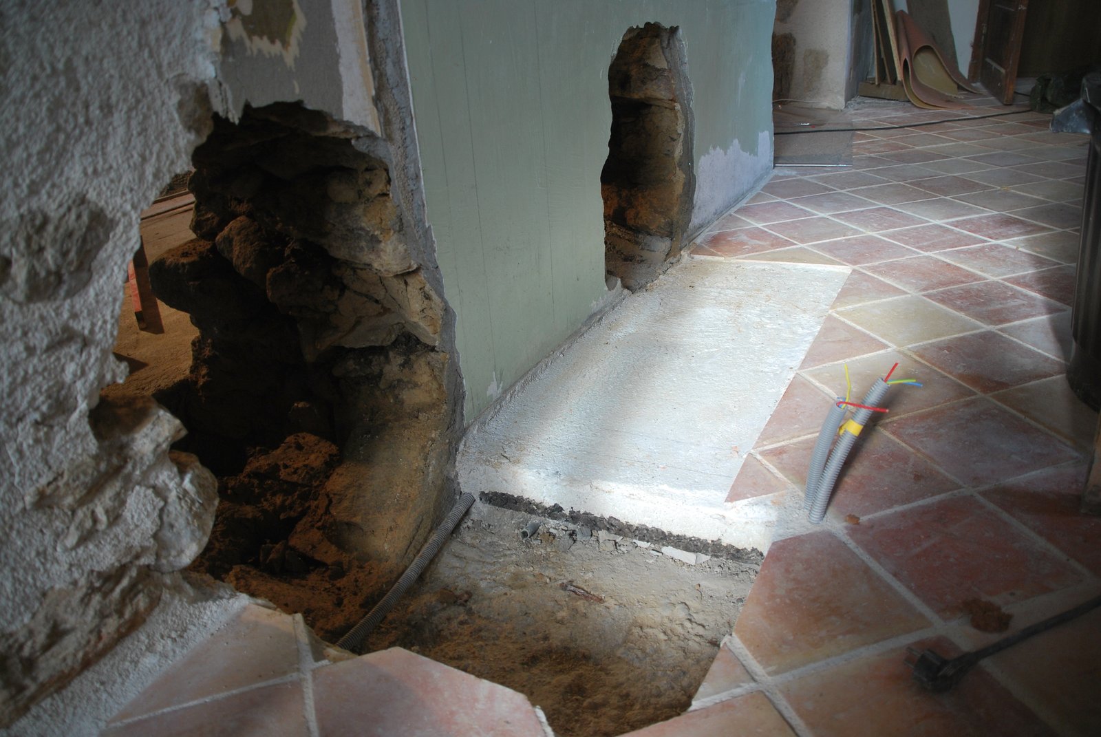
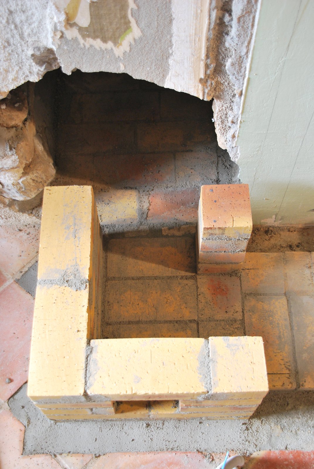
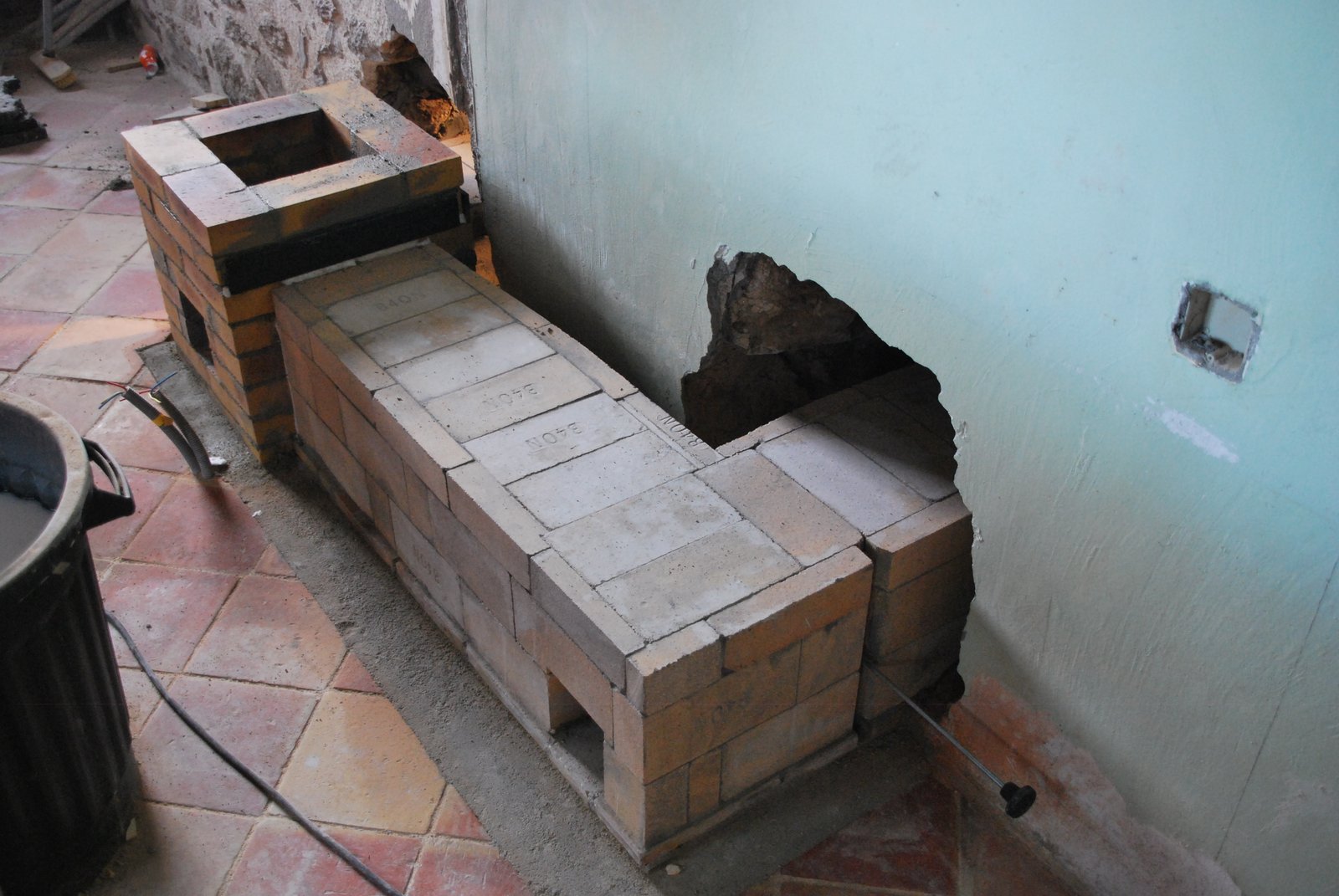
The far side of the wall. The chimney's location is in the for ground to the right of the cookstoves transmission tunnels opening in the wall, and the run of the heaters transmission tunnel behind it. Note a lime concrete skim slab was pored inadvertently on to a 3cm thick layer of cork insulation by the home owner. This slab was cut away and the cork removed.
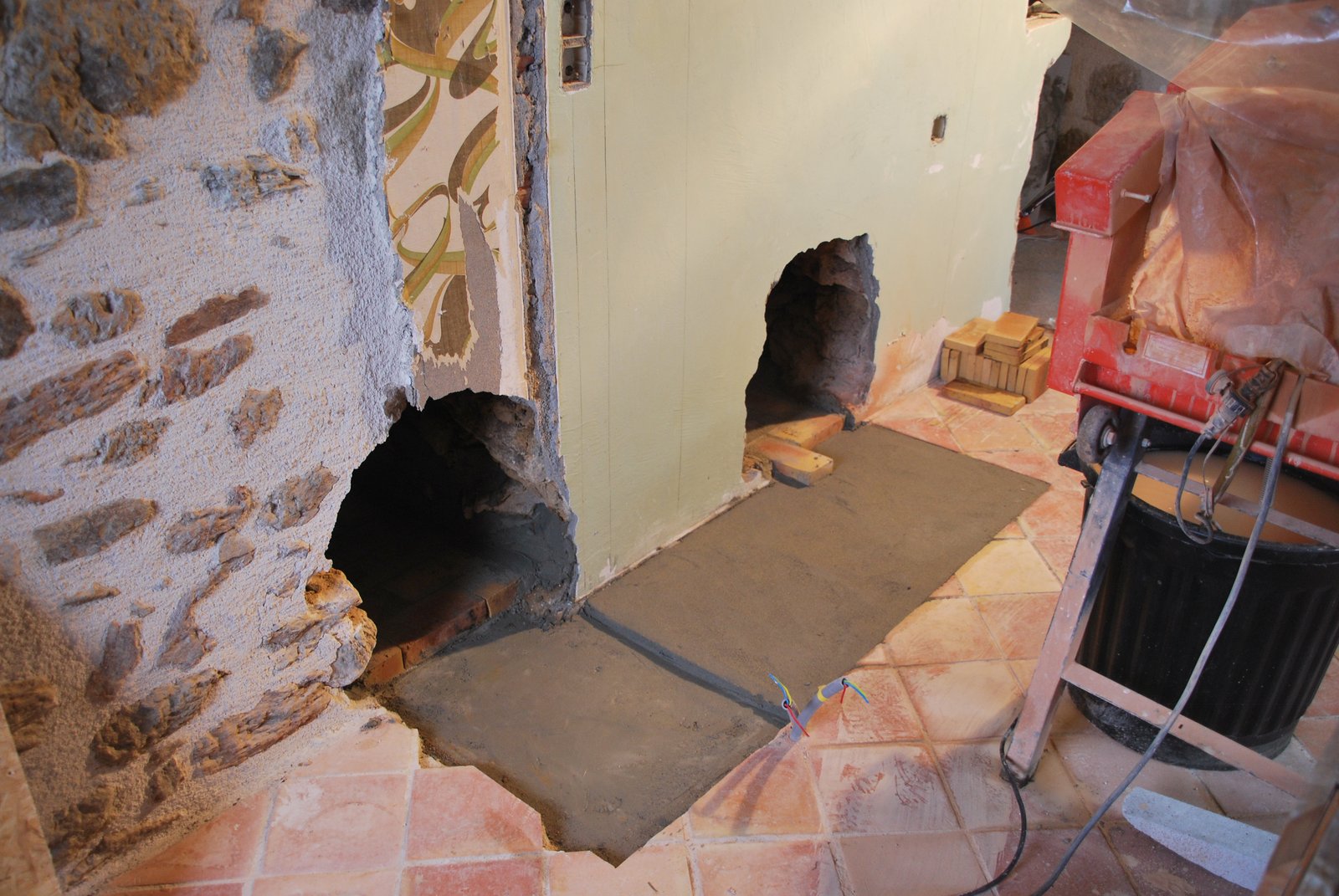
The chimneys footing is pored in cement based concrete. Note: This footing though only exactly the footprint of the chimney, rests upon a larger cement concrete slab, and serves primarily to bring the location of the first course of brick of chimney up to the hight of the cookstoves foundation slab on the other side of the wall.
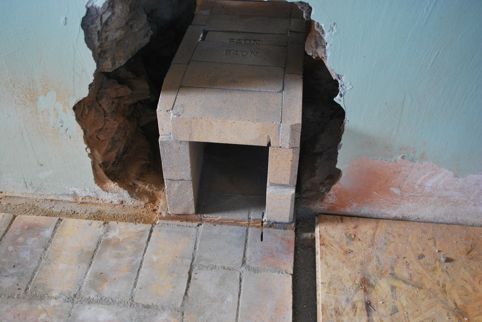
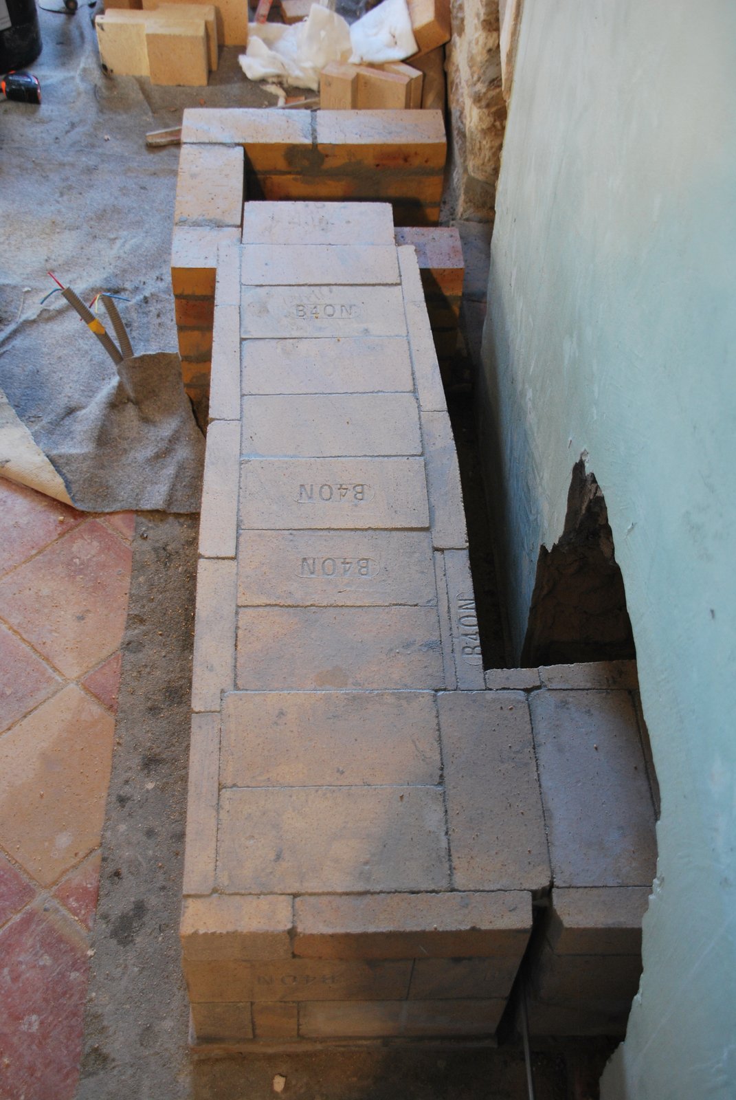
The slab for the tunnel is re-poured (after the cork has been removed) up to the hight of the finished tile floor in order to encase the electric cables that unavoidably run across the tunnel's footprint. The base course of the heaters tunnel will be layed in splits, seen at the right of the opening, to arrive at the same hight as the cookstoves tunnel, where both join the chimney.
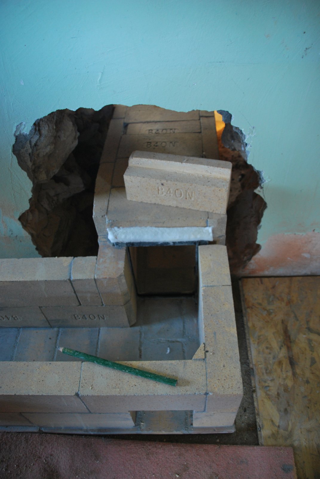
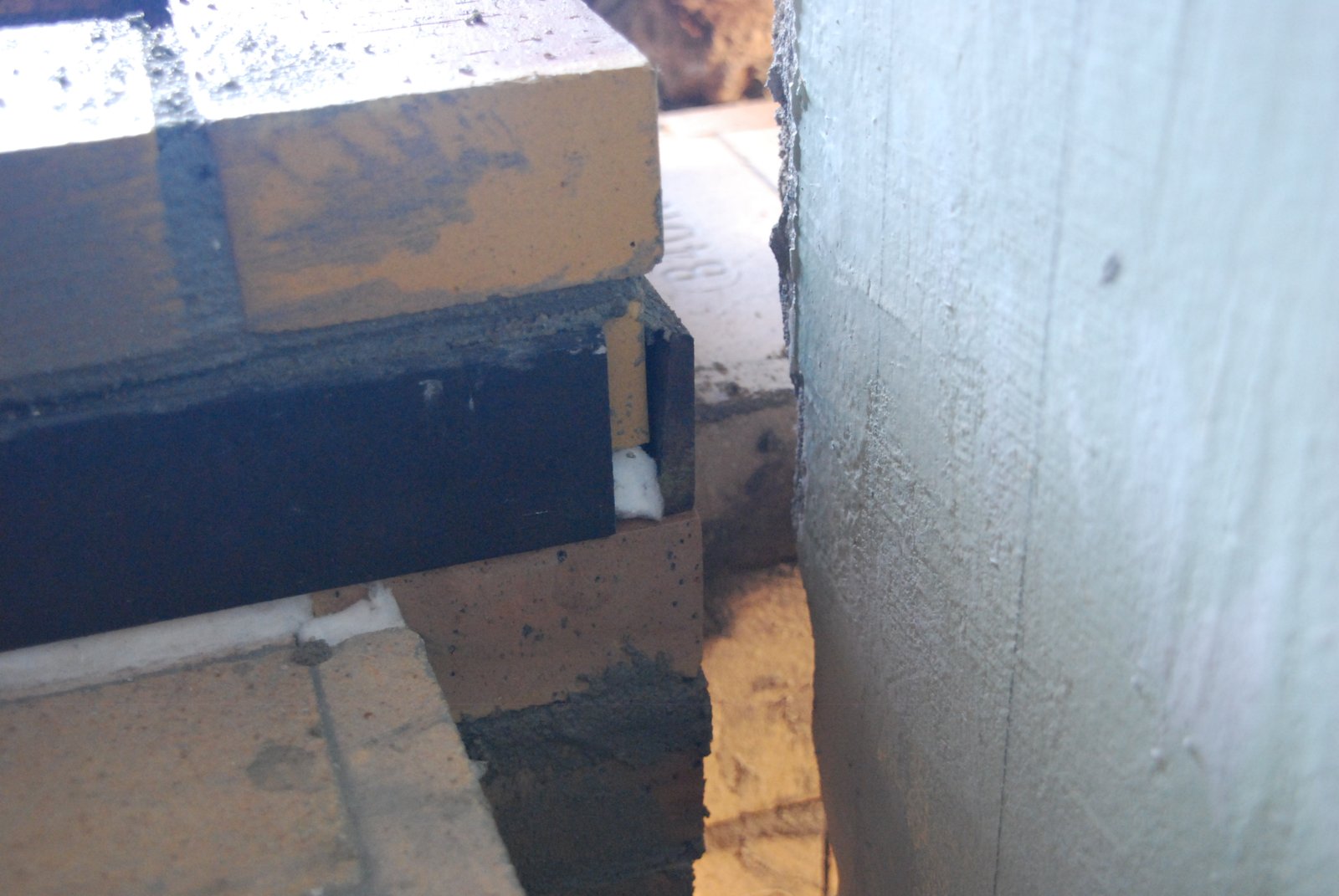
The heaters tunnel as it traverses the wall. It is at this point that the heaters damper will be installed. Note the wide groove cut into the base course to accept the bottom of the damper frame. The two thinner groves in the top and base of the tunnel are to accommodate the stabilization fins on the damper frame. These fins are intended to stop the frame sliding during operation of the damper. A semi circular groove is cut into the middle of the tunnels wall at right, (between the two courses that form the tunnels wall) to accommodate the bulge in the frame where the guillotine plate handle passes into the frame when the damper is in the closed position. (see next image)
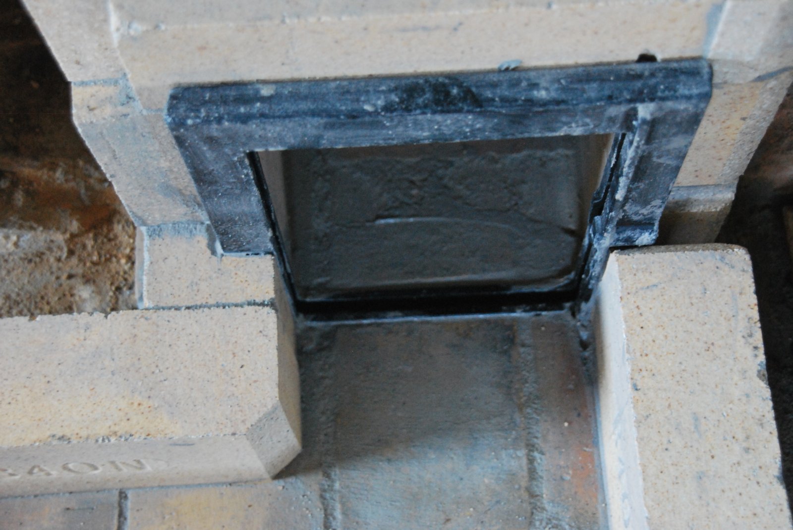
Note that the sharp corners of the brick forming the tunnel wall to the right of the frame, have been rounded. This is to stop the edge of the guillotine plate catching, as it is re-inserted if withdrawn completely out of the frame.
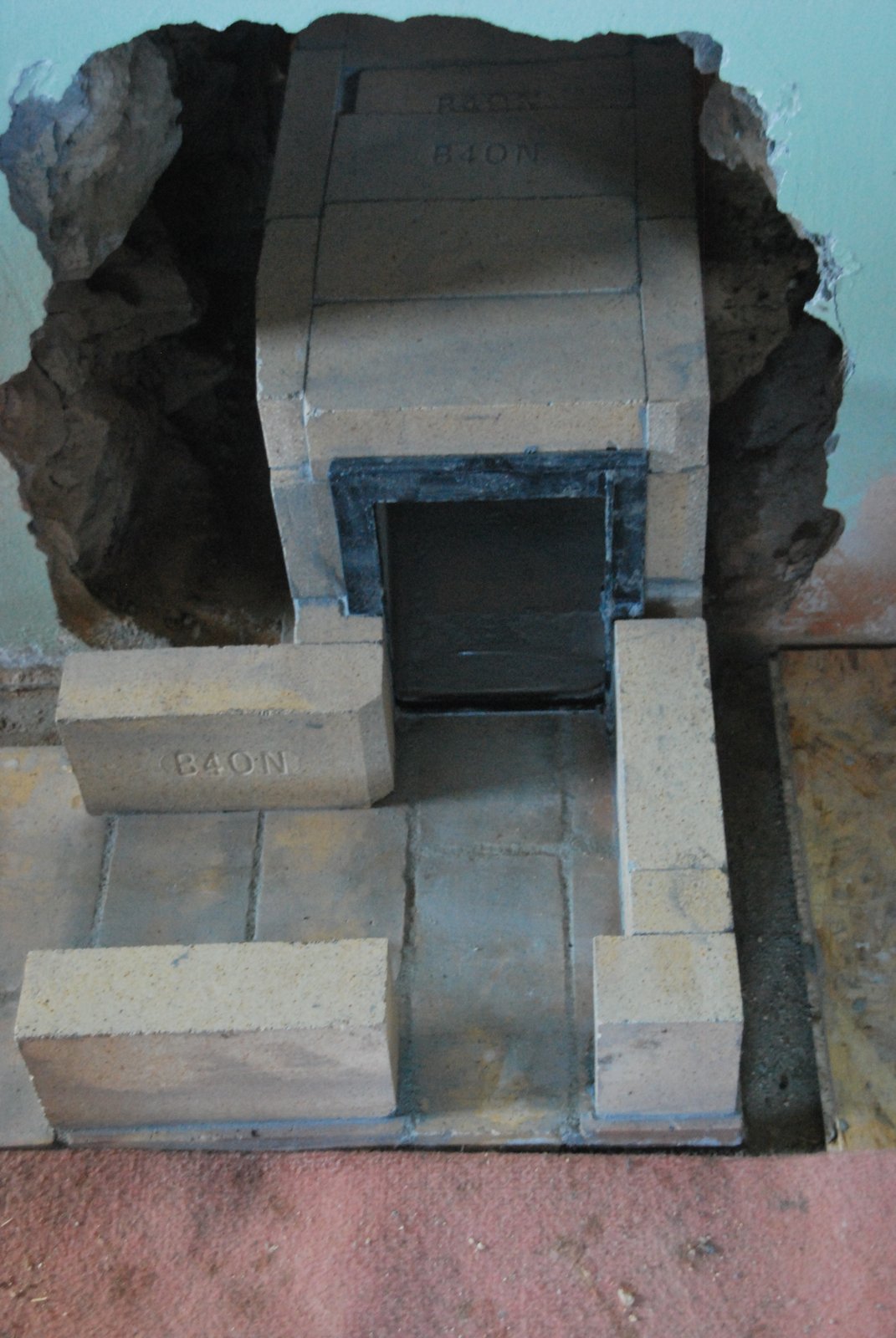
The damper frame in place. The frame is recessed into the groove in the base course to hold it in position and avoid the drag that would be created if it protruded into the tunnel.
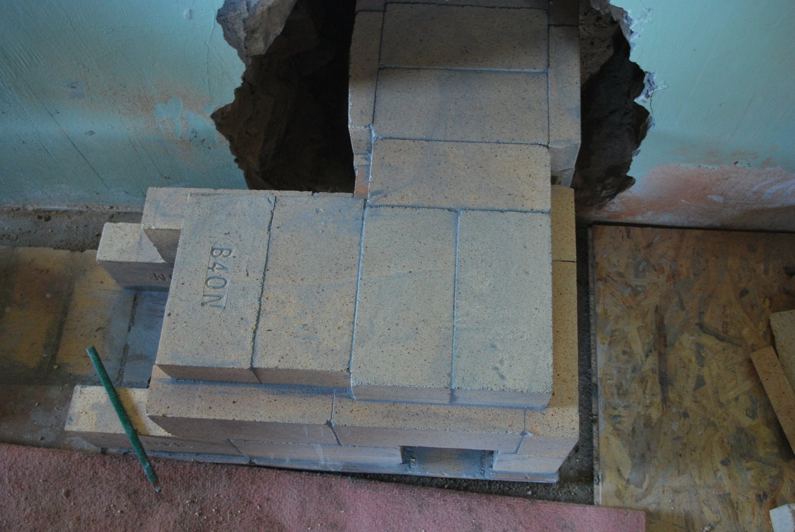
The 90 degree turn in the tunnel towards the chimney.
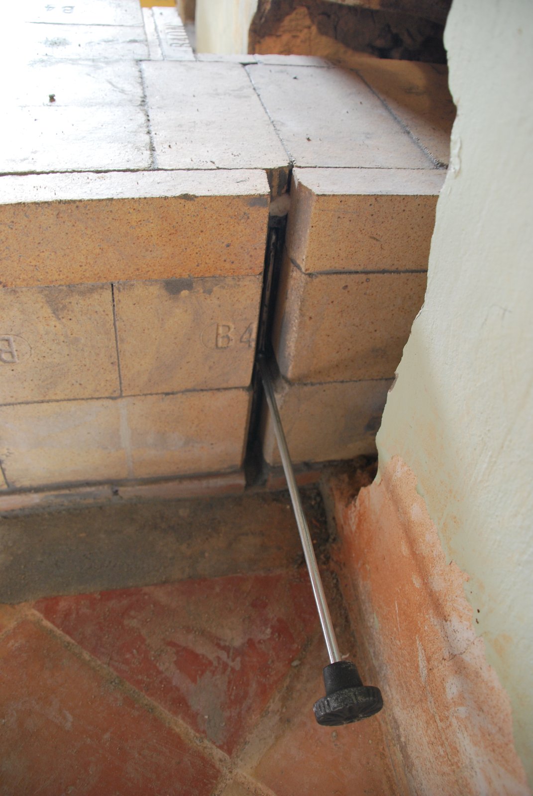
Like the bottom, the left side of the frame is trapped in the brick to avoid it being knocked out of place during operation There is no expansion gasket between frame and brick, as in this direction and under relatively low temperatures, there will be no expansion. Expansion of the frame as a whole will be via the top and the right side where it will be gasketed, and open to allow withdrawal of the guillotine plate, respectively
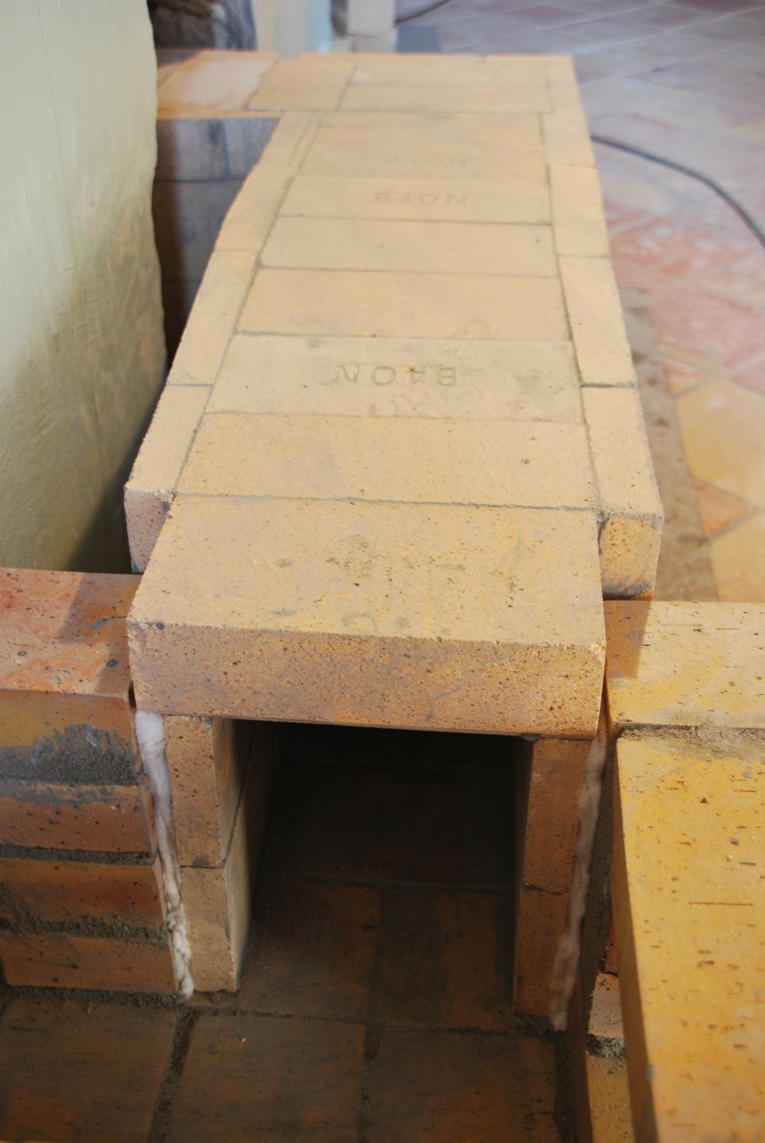
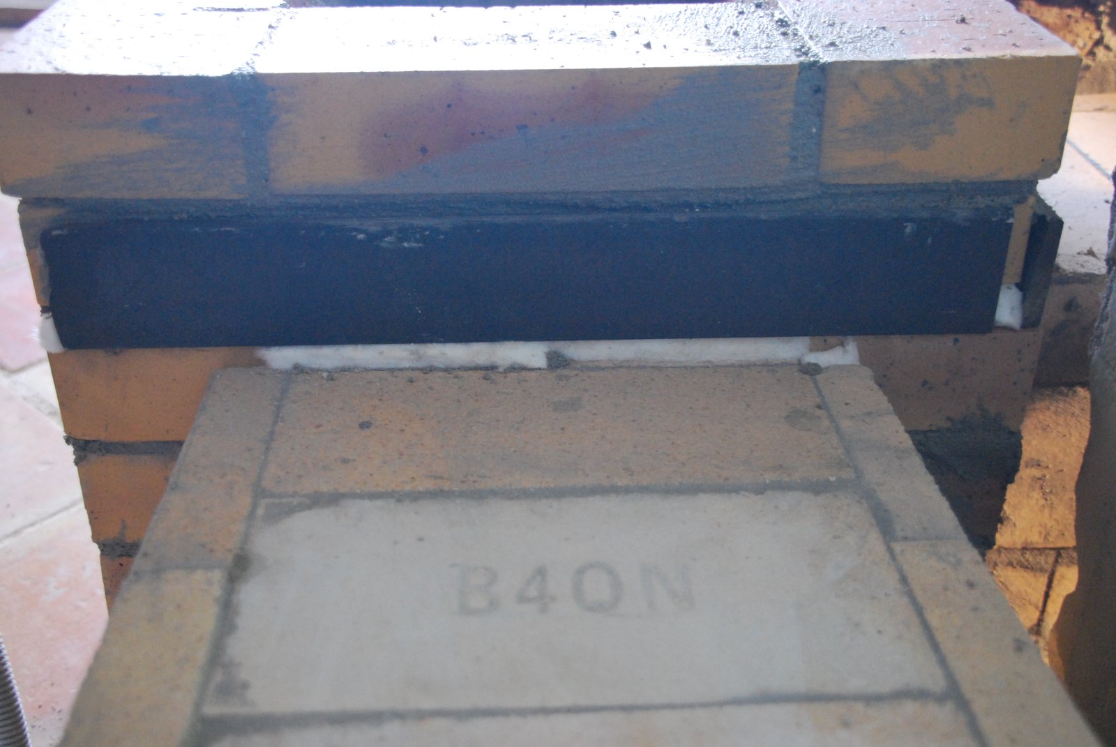
The access opening will allow cleaning and observation of the damper frame and access through the tunnel into the heaters left and rear manifolds.
The capping brick that traverses the tunnel over the frame is cut back on its under side to allow the intrusion of the top of the frame and its wool expansion gasket.
The damper is located in this position so that the operating handle pulls out close to, and parallel to, the wall, where it will cause minimal obstruction. The damper could also have been located on the other side of the wall, between the heater and wall. This would have been preferable in terms of operation as the fire could be observed during finite adjustment. But any failure would potentially necessitate partial demolition of the wall,or heater. In this position visual inspection and cleaning of the frame is possible through the access opening in the tunnel and replacement of the whole damper possible with minimal demolition of the tunnel
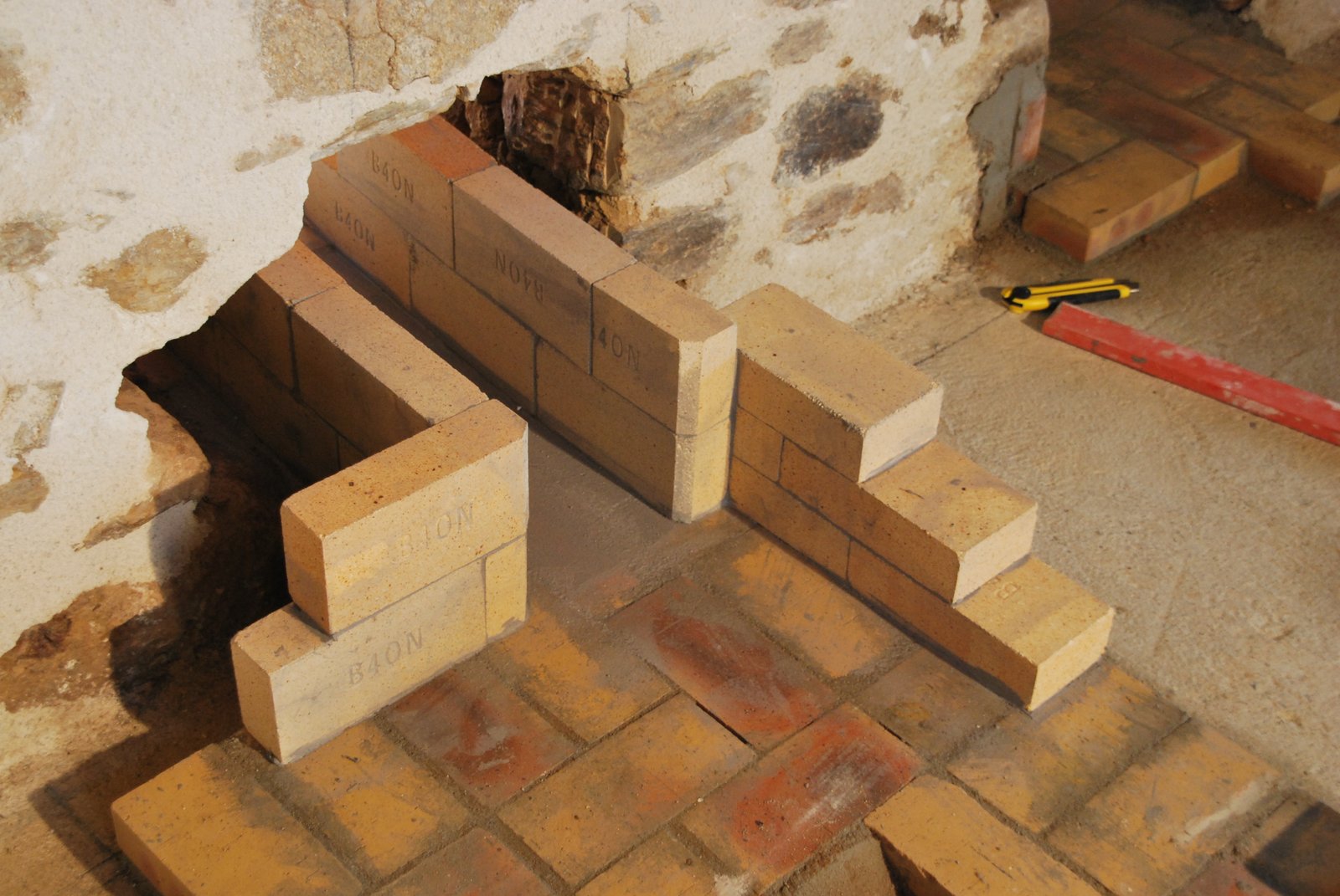
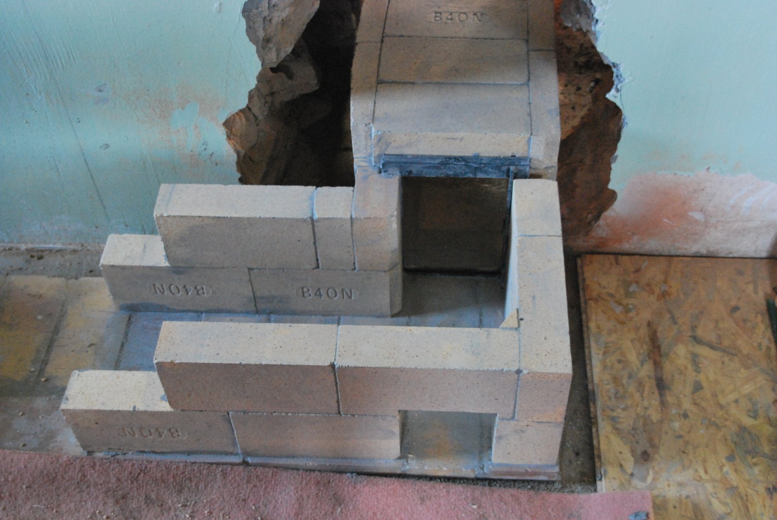
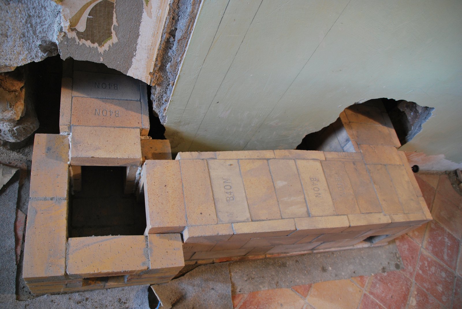
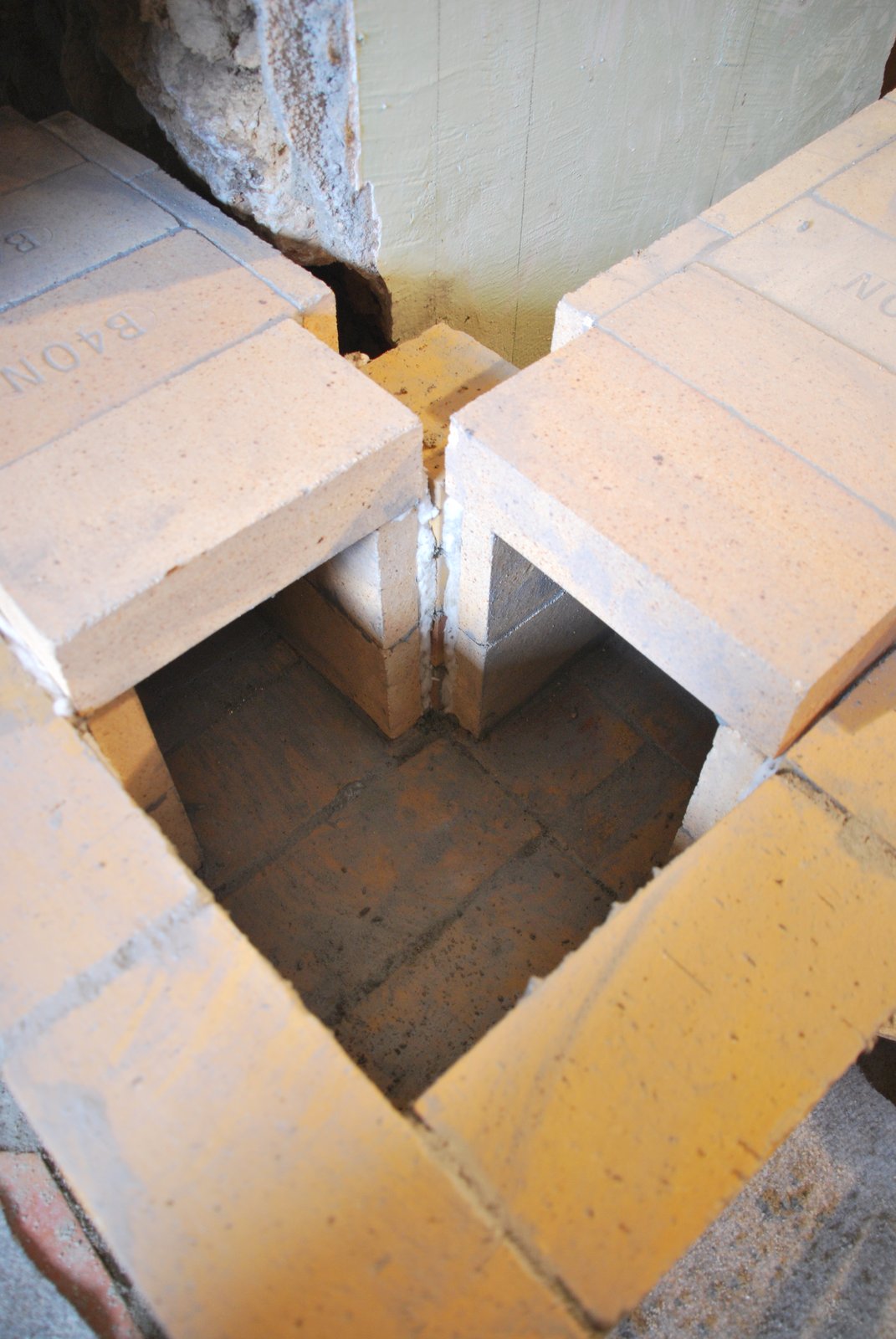
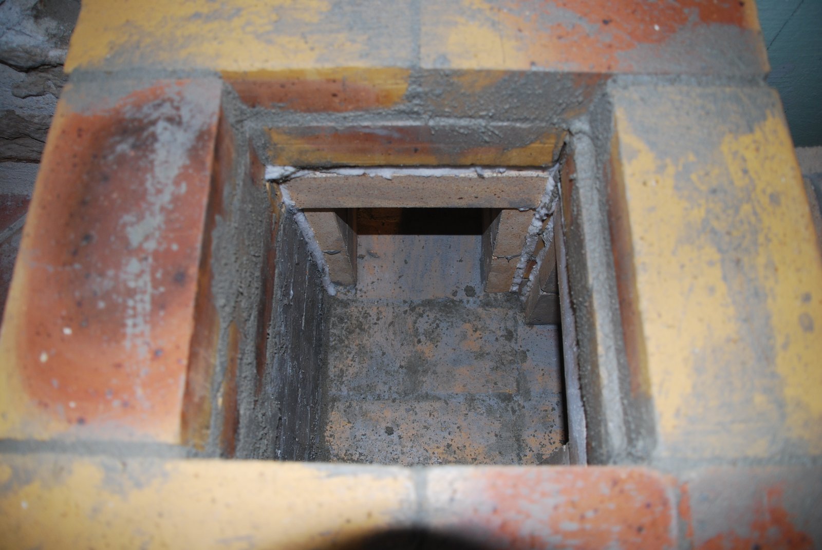
The first 4 courses of the chimney. As the connection openings for the two tunnels are adjacent to each other, and one of the two remaining sides would have to be cut out for the access opening, it would not be possible to connect directly to a flue liner tile and maintain its structural integrity There for a connection pavilion of brick will be built, onto which the first flue tile will rest.
Connection of the heaters tunnel to the chimney.
The column of half brick at the corner of the support pavilion, must be layed with care, and not dislodged during laying of the fire brick of the tunnels and the wool gasket between the two.
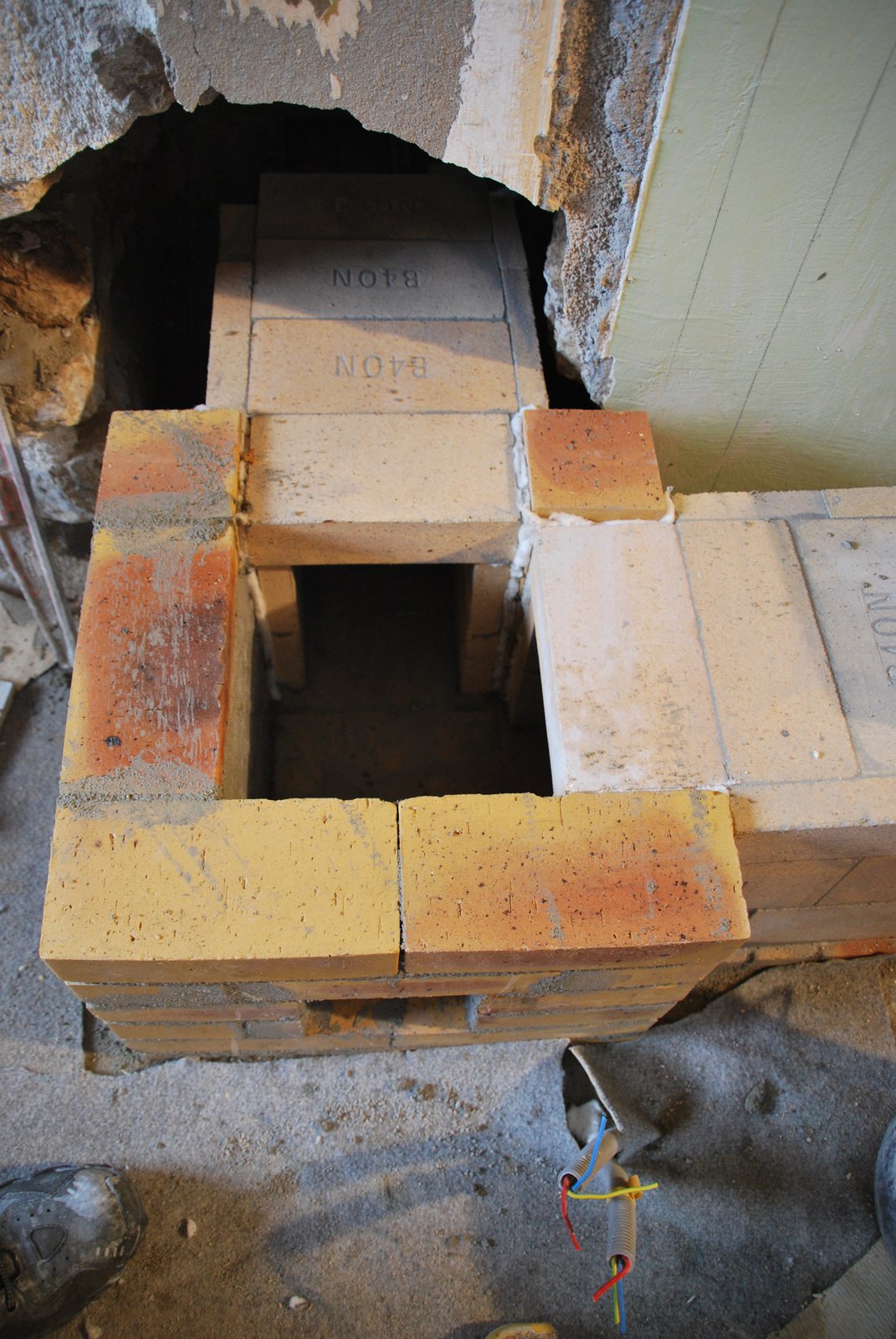
The cookstoves tunnel is connected to the support pavilion in the same manner.
The next course of the pavilion rises slightly above the hight of the tunnels to allow space for a wool gasket beneath the lintels.
Two 6mm thick angle iron lintels are used to span the openings in the pavilion. Each lintel is cut at a 45o angle where they rest upon the corner pillar.
Two courses of brick traverse the lintels and terminate the pavilion.
The space between the two lintels at their intersection on the pillar.
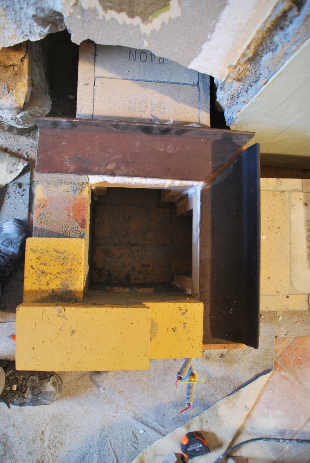
The completed pavilion and the two transmission tunnels.
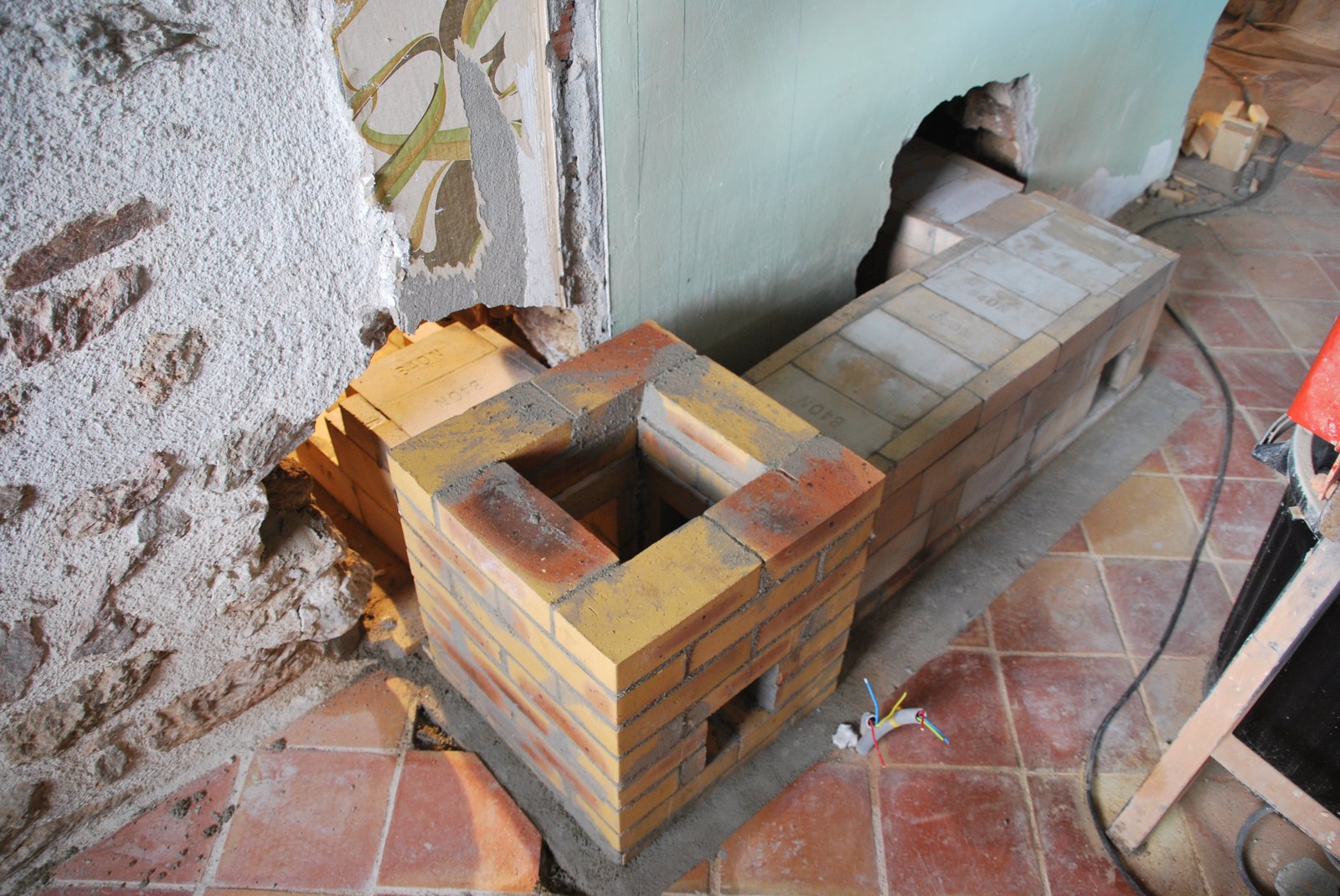
As the pavilion is larger than the flue tiles which will rest upon it, the facing of the pavilion will be larger than the facing around the flue tiles. Once above the hight of the pavilion the facing will corbel in over 6 courses until it is at the standard 55 x 55 cm format of the flue tile plus facing. The support pavilion and the flue tiles will be free floating within the chimneys facing.
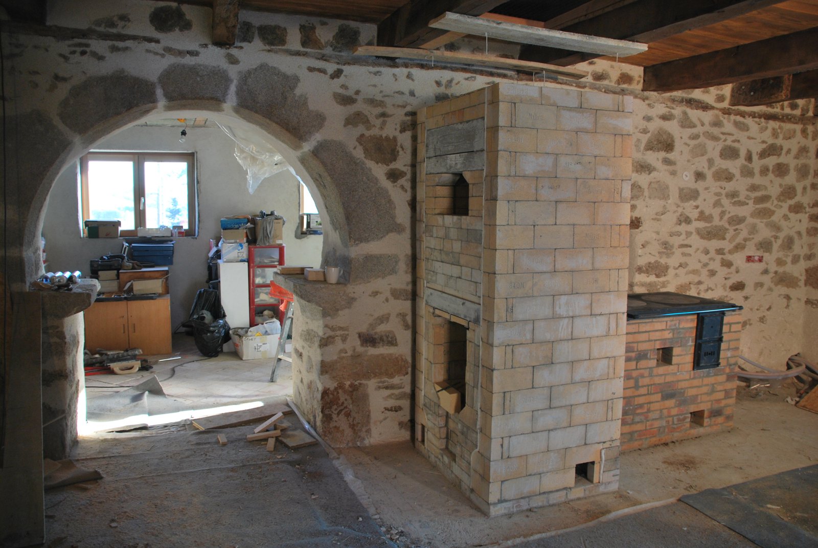
The heaters core and the cookstove on the opposite side of the wall to the chimney.
The arched opening represents the portal of the dwellings original souillarde. This was a small room with a vaulted stone cealing, typicle of the
region. It functioned as a sub kitchen. In this case it was demolished to build the extended portion of the house on the far side of the wall.
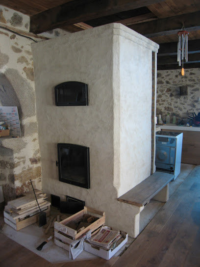
The heater faced by the home owner.