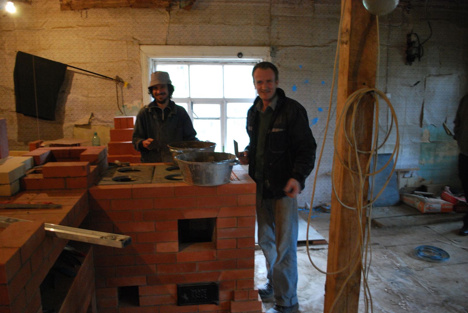
Detailed here is the construction of a Teplushka and cookstove at a craft centre in the hamlet of Agarkovo, about 75 km West of Moscow.
The project was executed by local stove master Alexander Batsulin and myself in the fall of 2009.
All images have an HD option. Click on image
The Teplushka is a variant of the traditional Russian oven developed by годах Ieosif Pondgorodnikov in the 1920s
Pondgorodnikov was an Engineer in thermo-technicks and progeny of Vladimire Grum-Grjimailo the world renowned metallurgist and exponent of the theory of gas buoyancy. (See W.E. Groume-Grjimailo's "The Flow of Gases in Furnaces")
In 1927 The Soviet Ministry of agriculture 'asked' several industrial engineers to put forward proposals to improve the efficiency of the traditional Russian oven.
It was the design submitted by Pondgorodnikov and Grum-Grjimailo that the ministry deemed the most viable.
Of the 15 variants of the same basic design, one was chosen and used to replace the existing working drawings for the Russian oven, published by the department of construction in its manuals intended to assist auto construction in the countryside.
Krestianskaya Teplushka is the actual name of the stove, which roughly translates as "peasants stove".
Teplushka is also the name of a specific style of railway wagon for common people.
Other meanings of Teplushka are, heated shelter, and heated goods wagon. Teplo being heat.
The primary problem with the traditional Russian Oven is that it is built upon an elevated hollow foundation, the active mass being at least 4 feet higher than the dwellings floor. This causes an uneven stratification of radiated and, particularly, convected heat within the room.
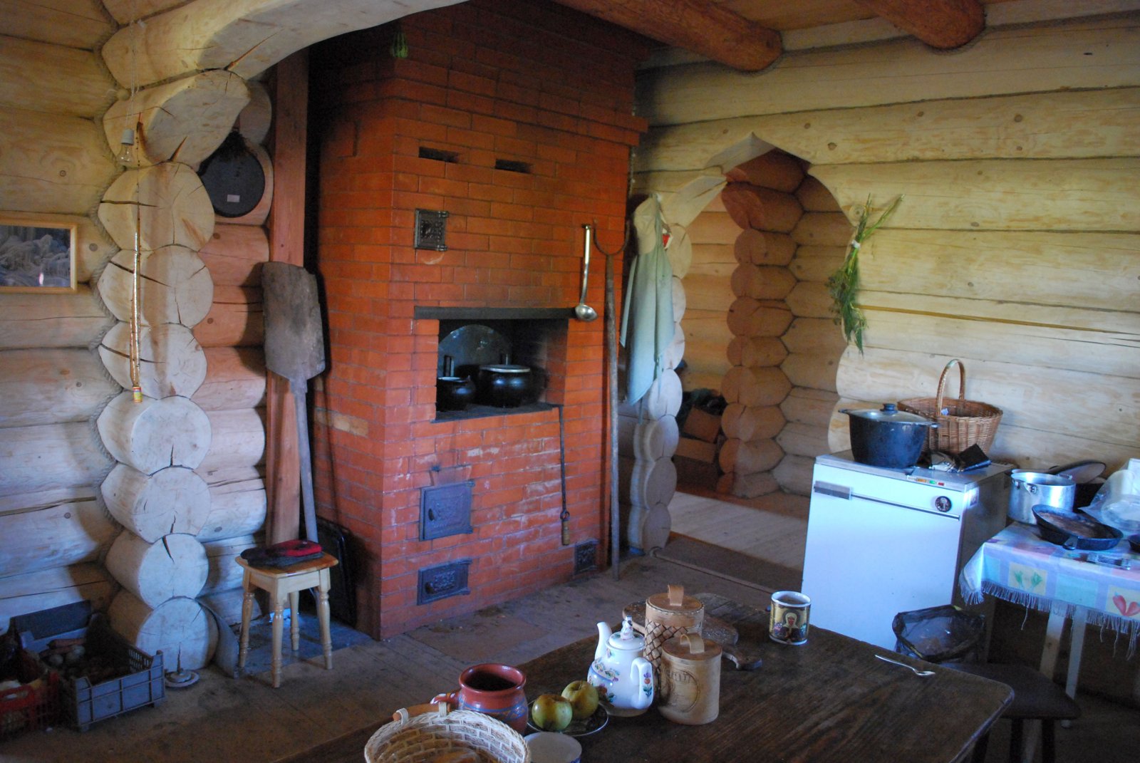
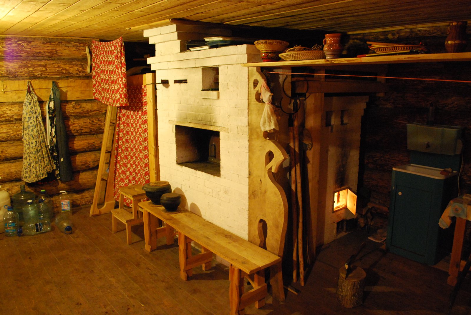
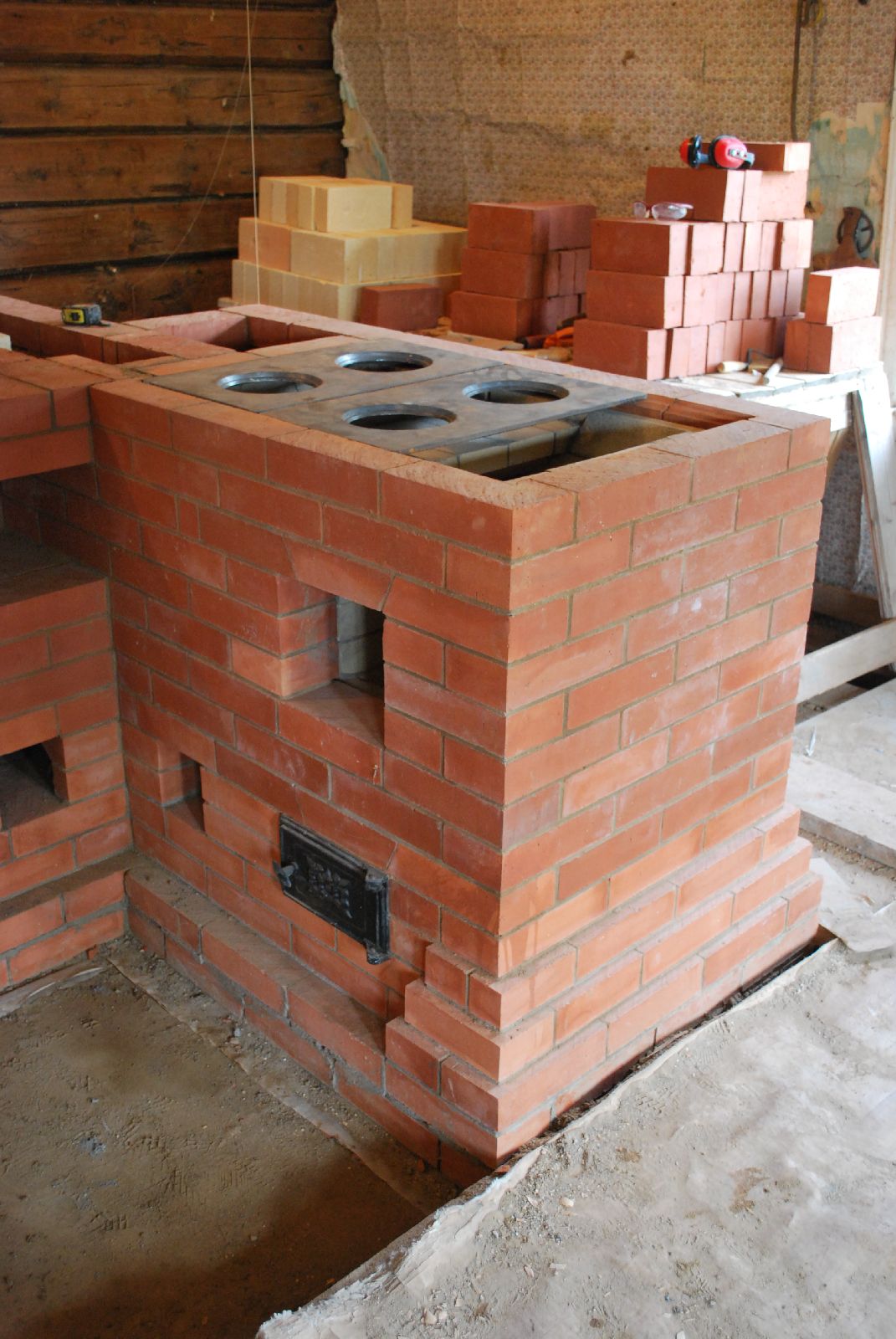
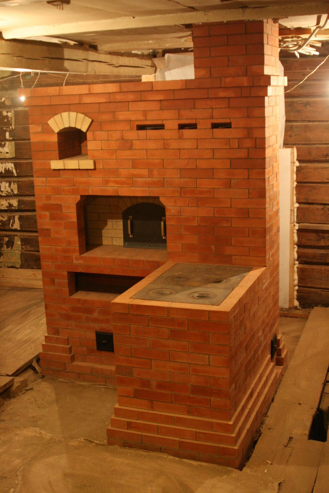
Teplushka in the centre at Argarkovo, built 4 years previously by A Batsulin. One of the many variants of Podgnrondnikov's basic design, this Teplushka has a cook top above the fire box in the hearth of the avaloire. Rather than a sleeping platform there is a bell chamber above the vault. The whole structure supports a second stove on the floor above.
Efficiency Test Of This Stove (pdf)
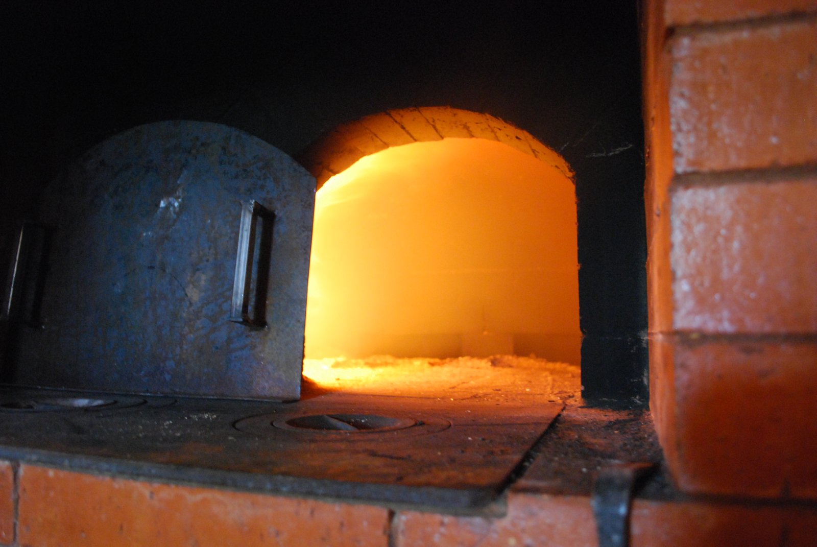
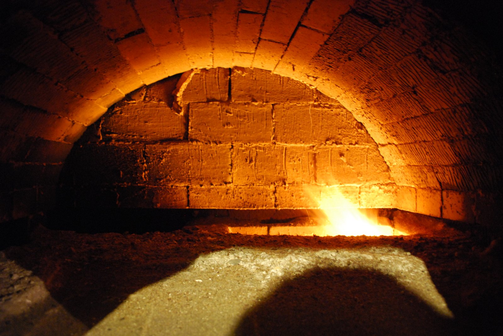
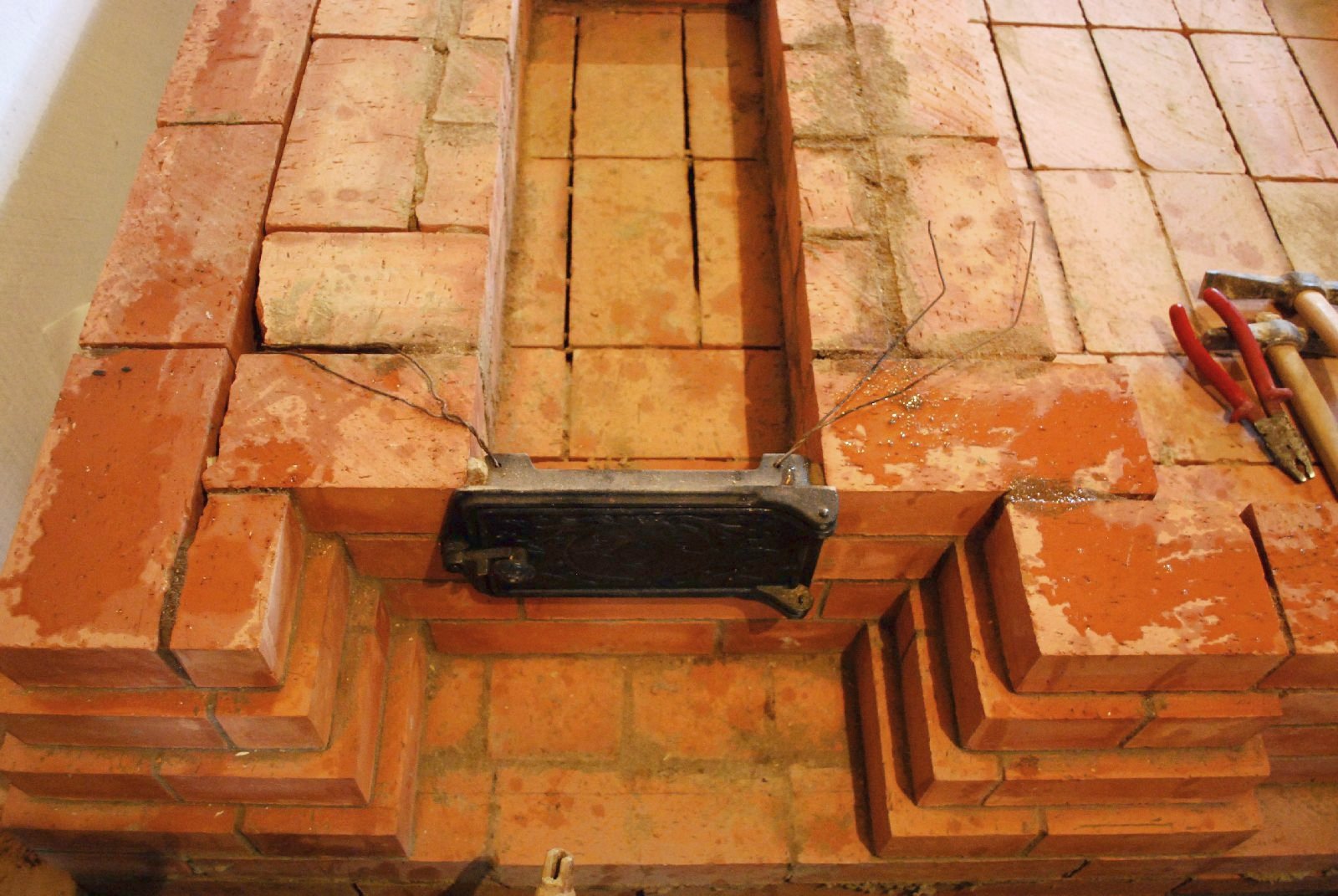
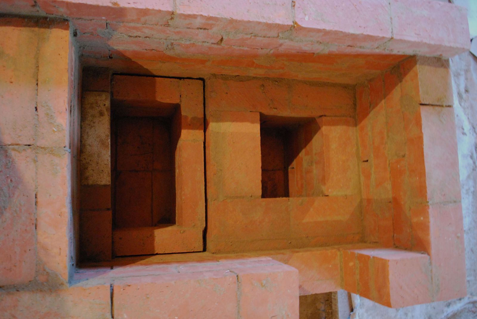
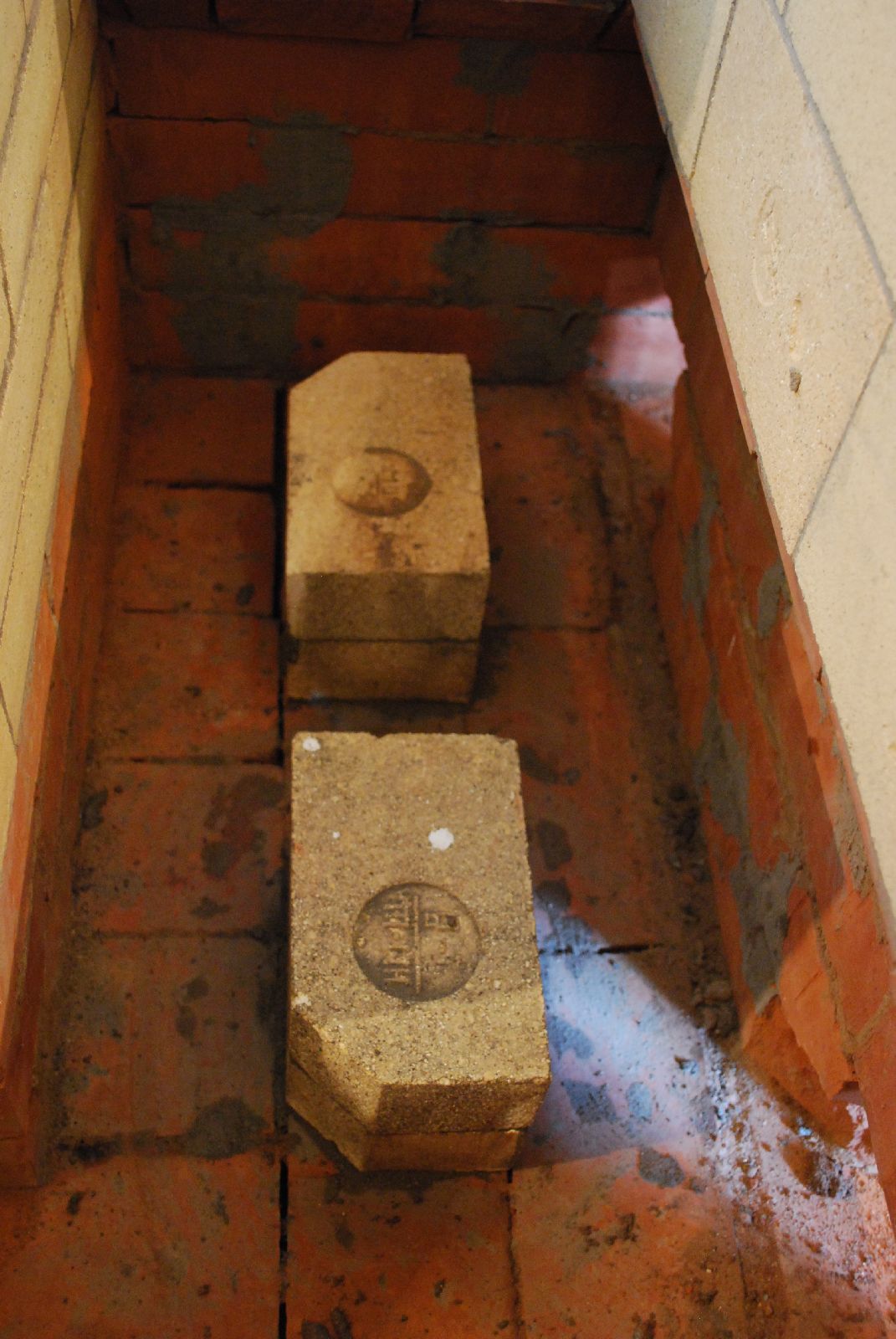
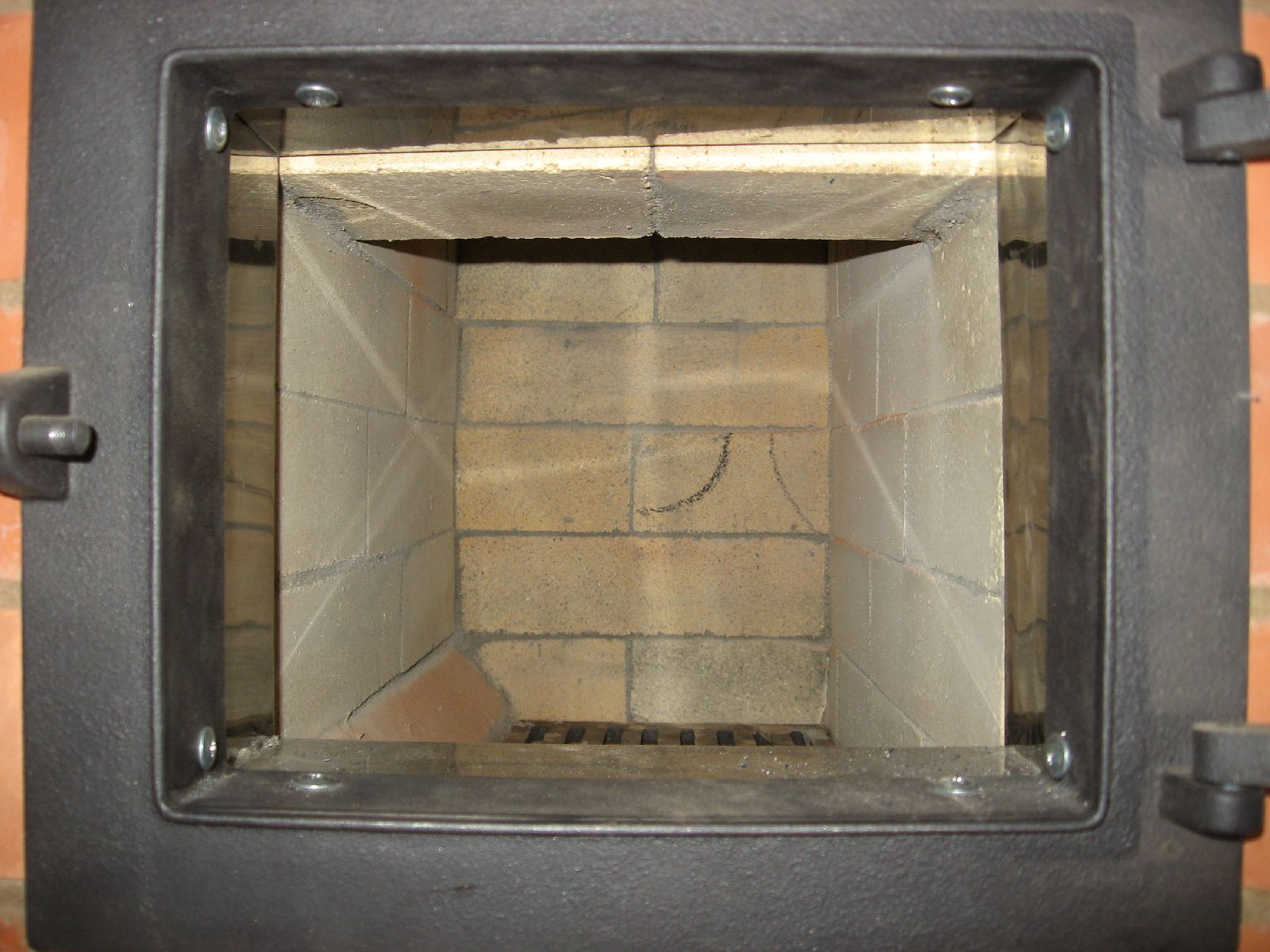
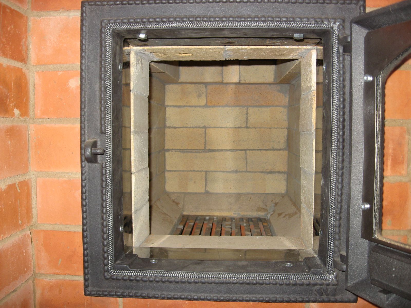
The bake chamber during remote firing.
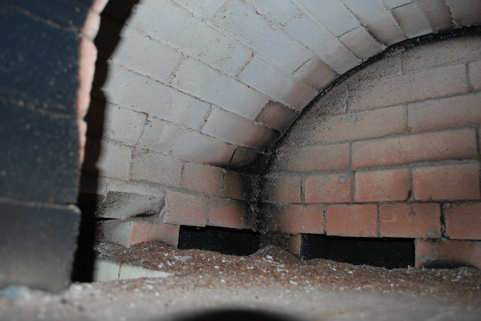
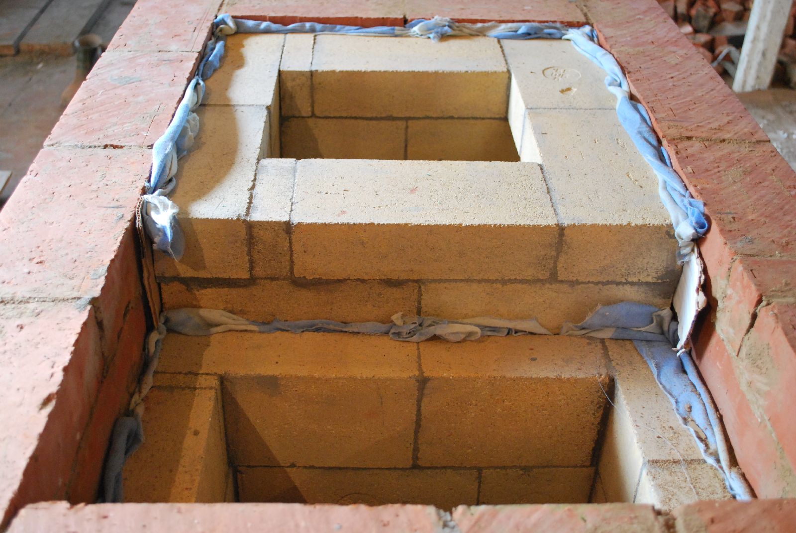
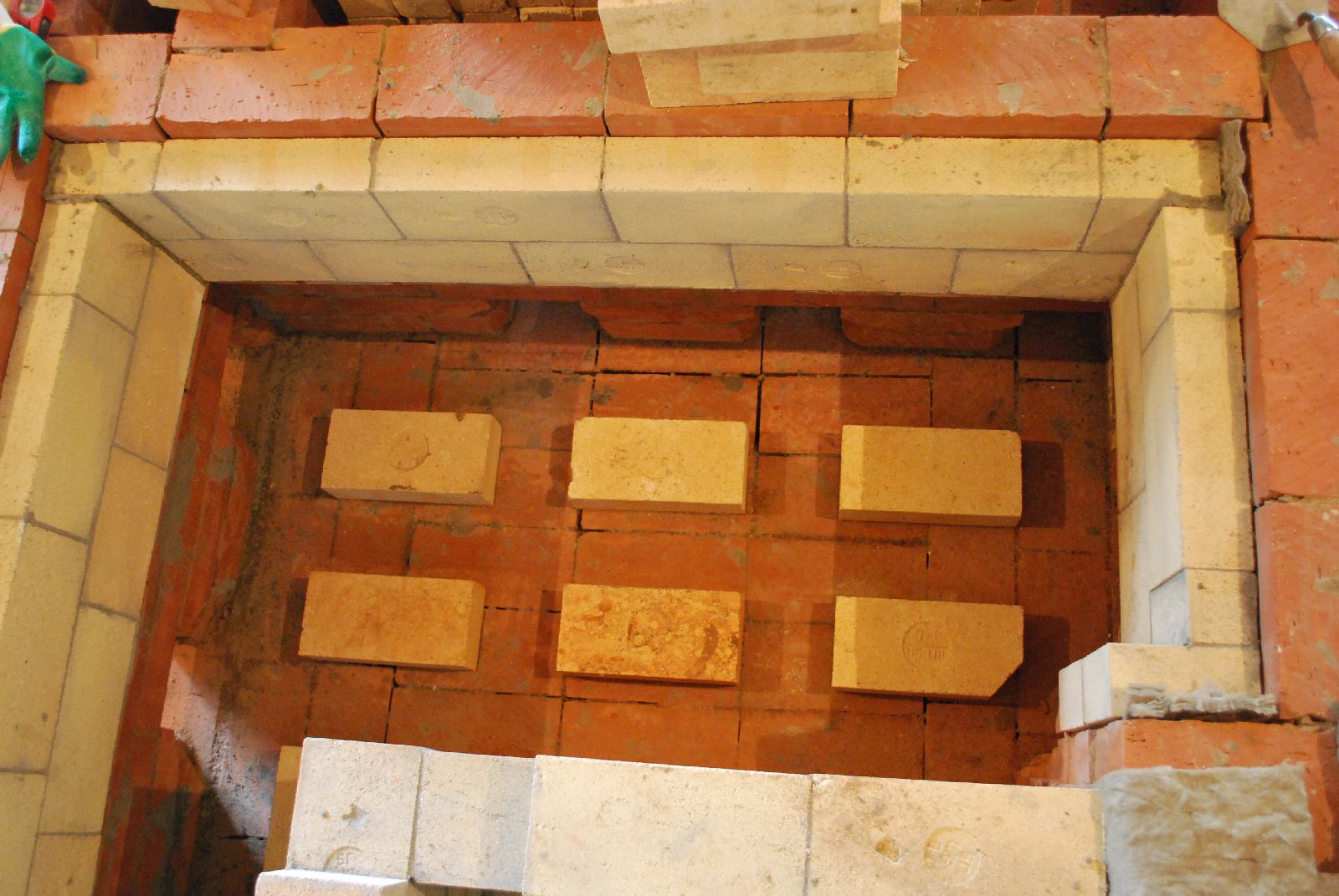
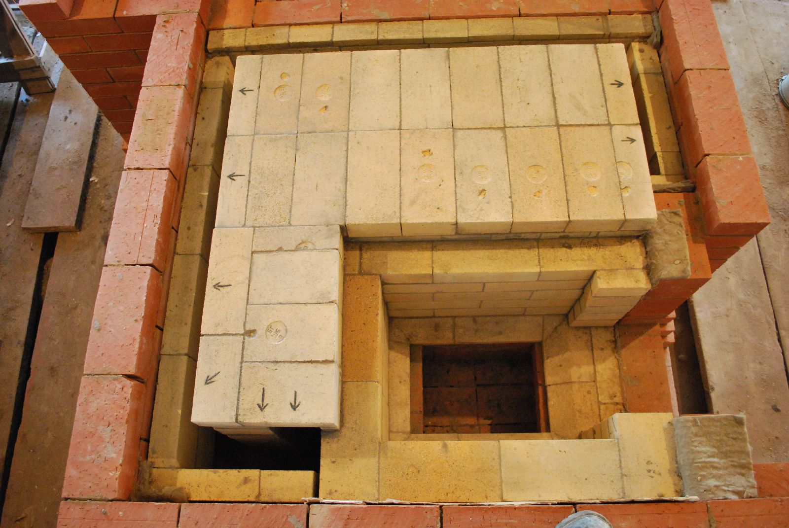
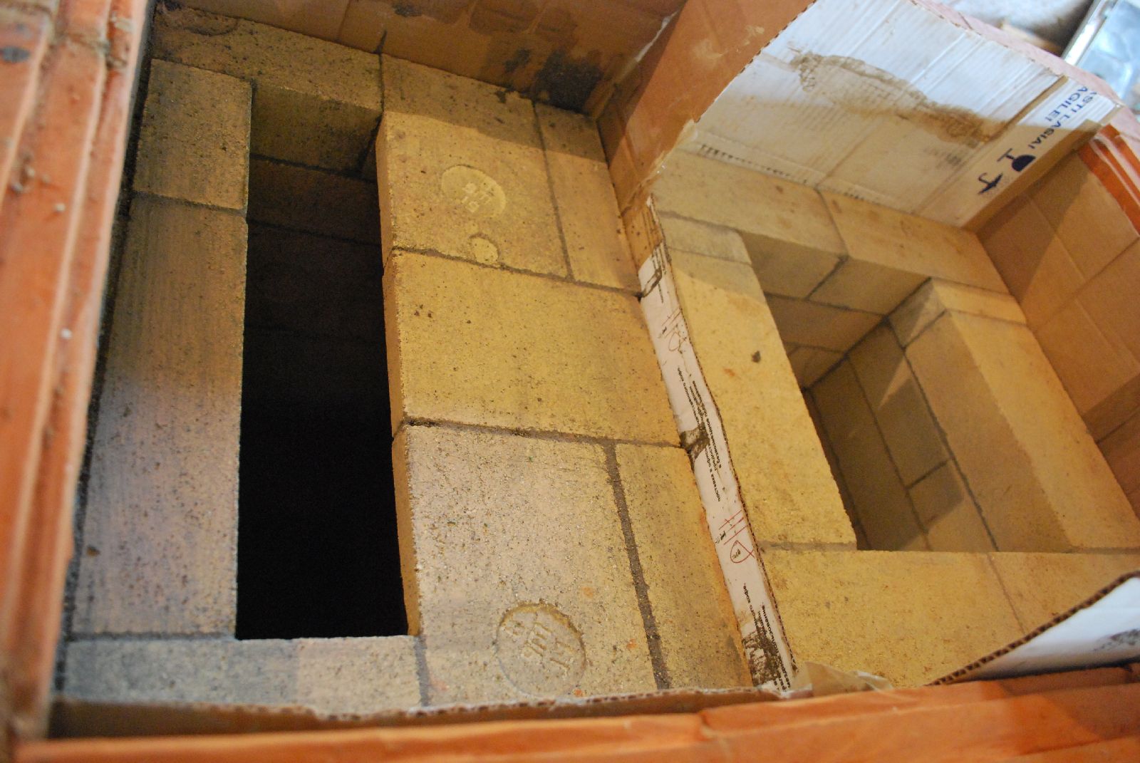
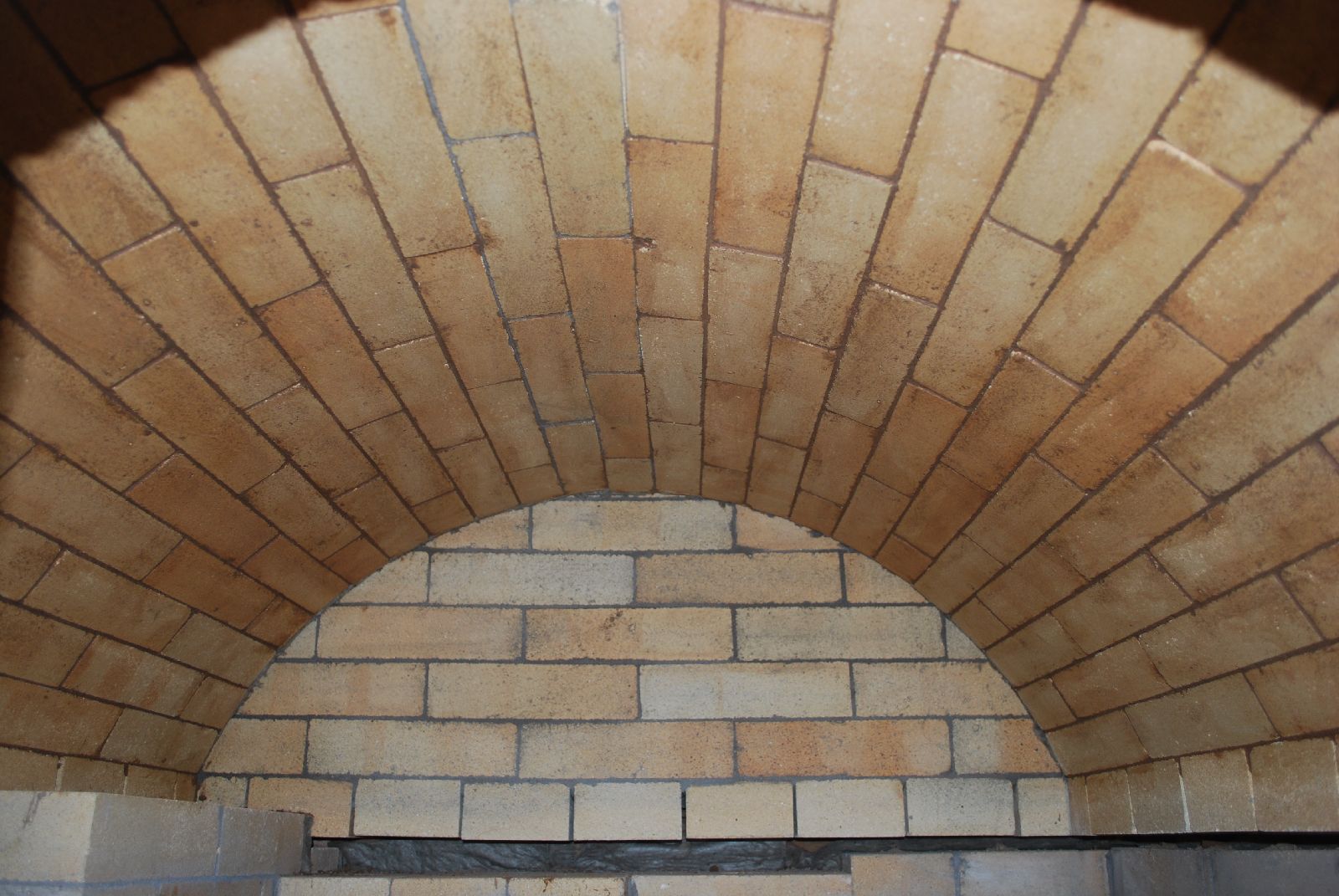
The bake chamber after firing. The vault is in common clay brick laid in clay mortar. The throat from the fire box is at the bottom left and two of the four down channels to its right.
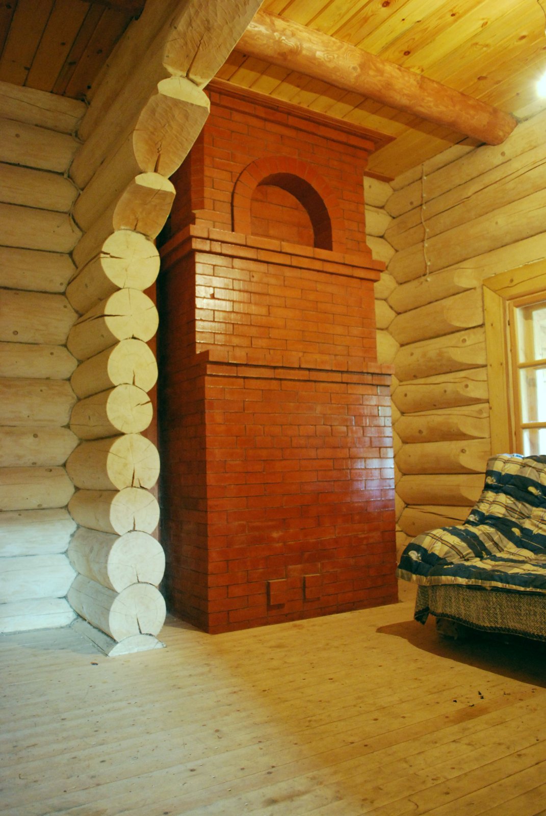
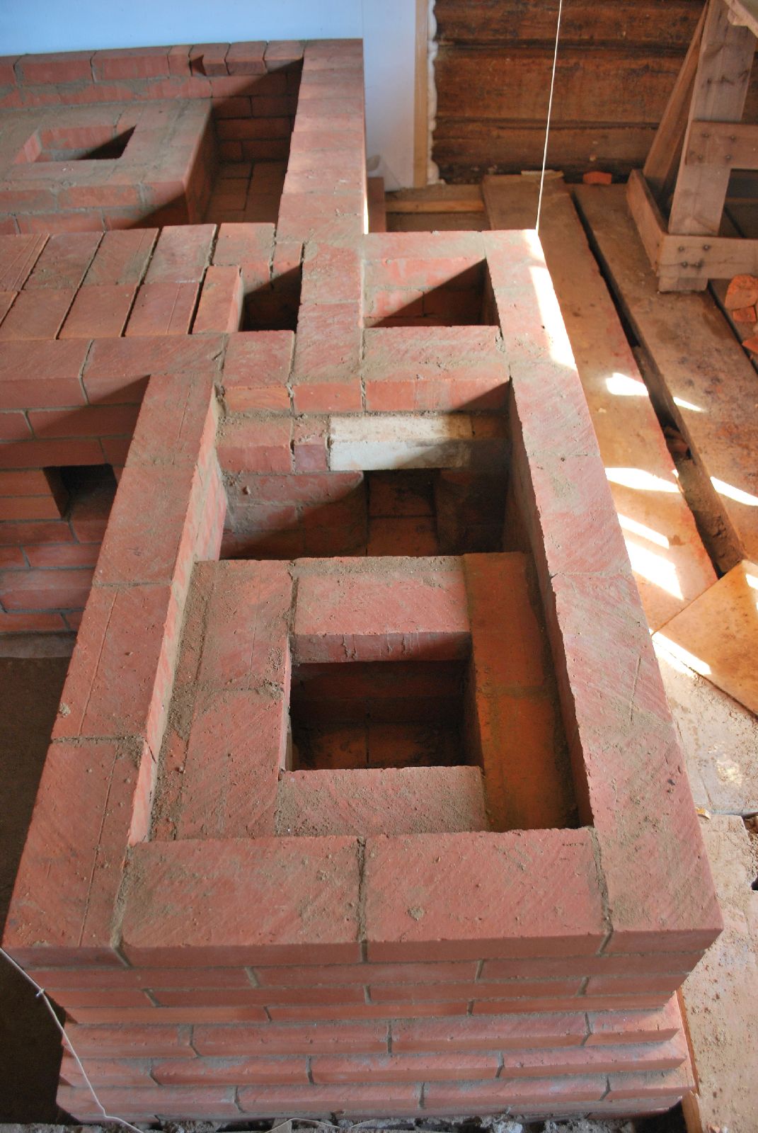
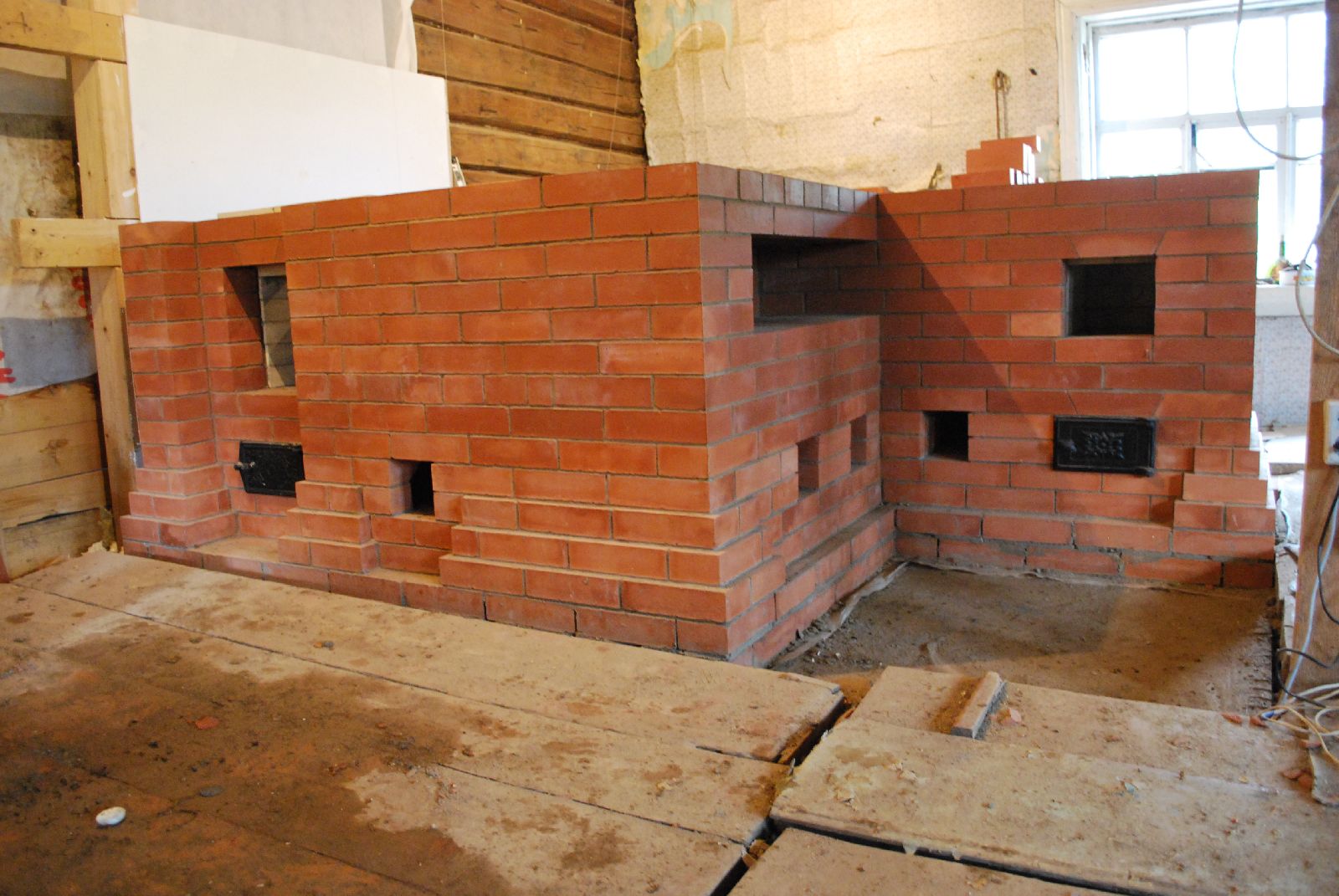
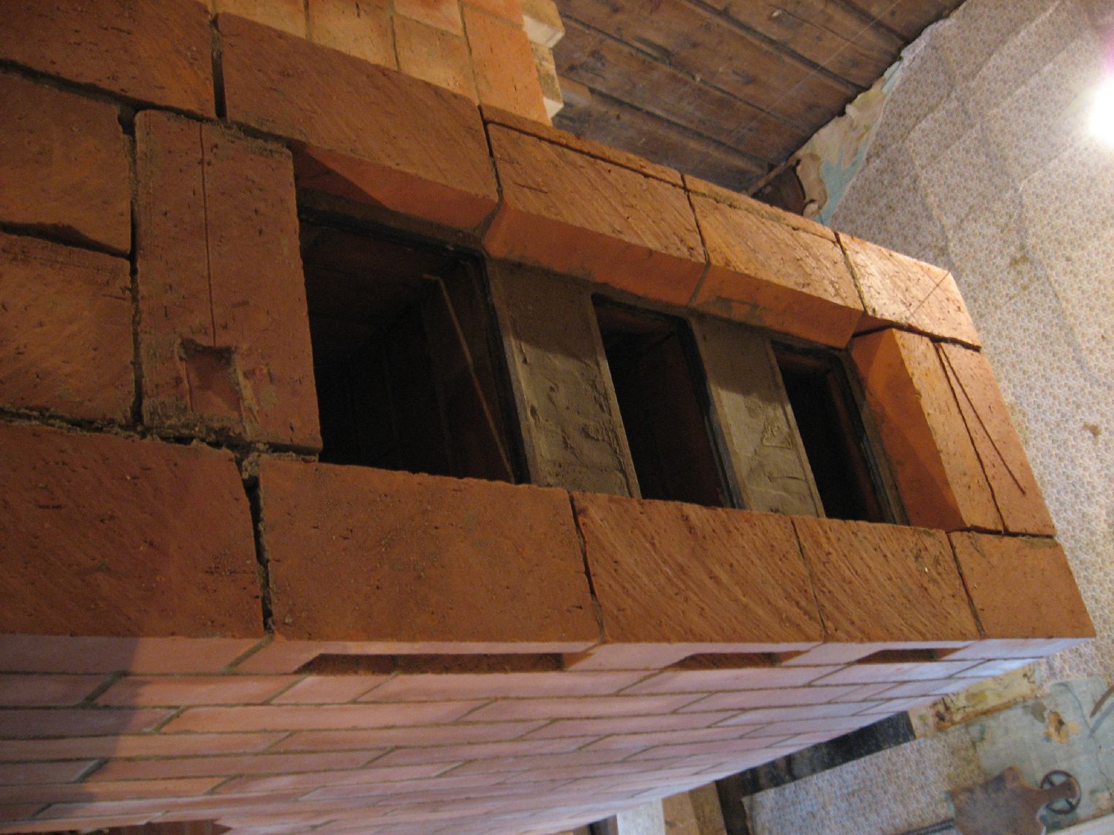
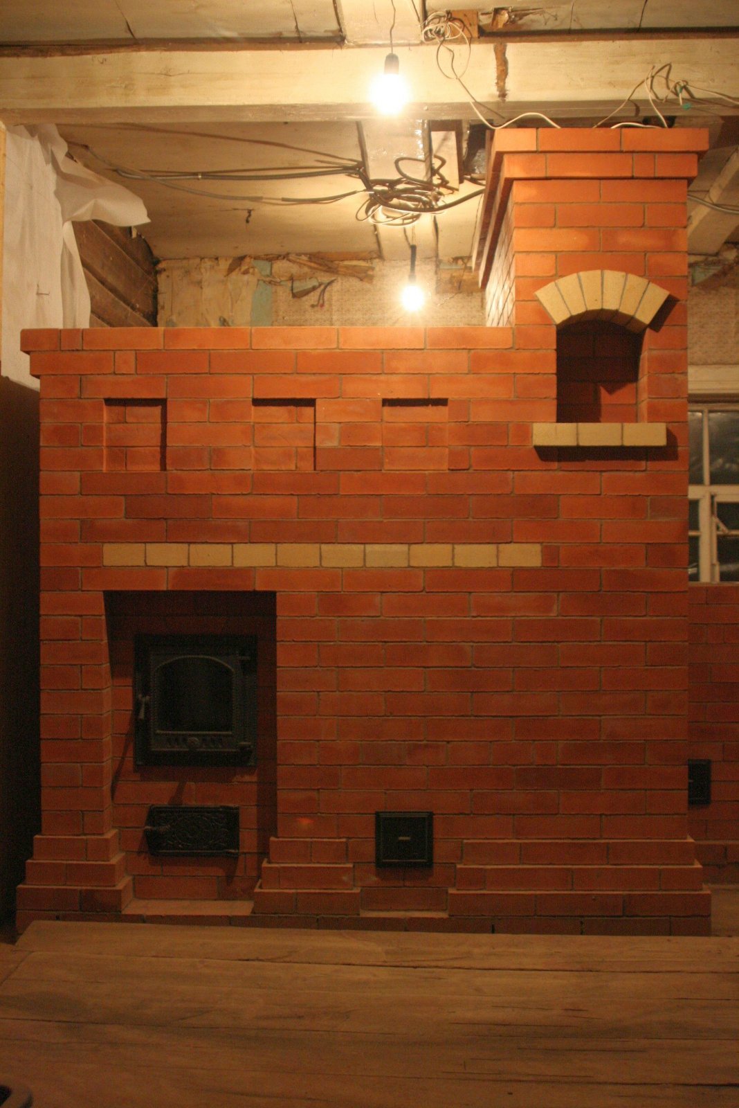
Seen from the room behind the kitchen. The bottom of the three distinct portions of the structure is the stove and bake chamber. Above that is the bell captivator and on top the blind arch, which is structural masonry supporting the stove on the floor above.
Key
a: Fire box
b: Throat or in channel from fire box to bake chamber.
c: Out Channels, from the bake chamber to the lower chamber
d: Hearth support pillars
e: Hearth
f: Loading Opening
g: Shut off Damper from the avaloire
h: Shut off Damper from the under hearth smoke path
i: Ash box/ air intake door
J: Chimney
Red line-- smoke path during remote firing.
Yellow line -- smoke path during direct firing.
Blue line -- Primary Air.
Note: In this diagram the vault of the bake chamber is not shown
The Teplushka has a remote fire box located below and to one side of the ovens loading opening. The flame enters the bake chamber through an 'in' channel, between the fire box and the hearth , splashes across the volt, and then is drawn through a series of 'out' channels in the vault wall at hearth level.
The gases are drawn down these channels into a lower chamber before being 'collected' by a manifold with several openings, and drawn in to the base of the chimney. This results in the lower portions of the stove being heated, and much more captivation.
There is a damper located between the avaloire and the chimney, allowing the Teplushka to be fired in summer in the same way as the Russian Oven. That is, to light a fire directly in the bake chamber, rather than the fire box. When fired in this way the lower smoke path is by-passed, and so not heated.
Teplushka being fired remotely. There is a sleeping platform behind the avaloire.
The bake chamber during remote firing.
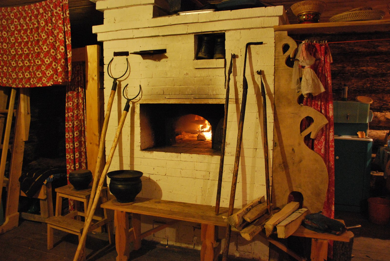
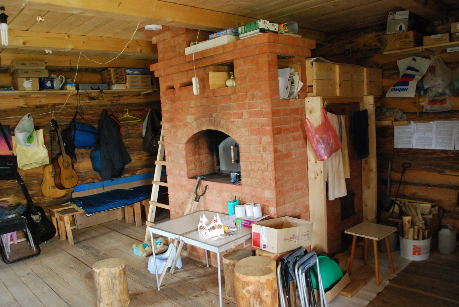
The same Teplushka, boasting an array of tools, being fired in the bake chamber. The stove was built 6 years ago by A. Batsulin in the region of Kaluga.
Teplushka by A Batsulin. Kaluga.
Note the wooden sleeping platform and its ladder. Detailed firing instructions are afixed to the wall at right.
The objective of the project was to line the lower chamber and rear wall (behind the vault) of the Teplushka, with refractory brick shiners, to prevent cracking of the facing, and begin to move towards eventual double skinning of the whole stove. The cookstove would also be double skinned, and its fire box free floating.
Refractory mortar will be used to lay the refractory brick rather than clay mortar, and the clay mortar of the facing will be enriched with 10% of Portland cement, and its clay content reduced. Some portions e.g. the vault and hearth will be laid in clay mortar i.e 3 sand to 1 clay.
This article records only an event as it happened, and is not intended to expound any particular theory or technique.
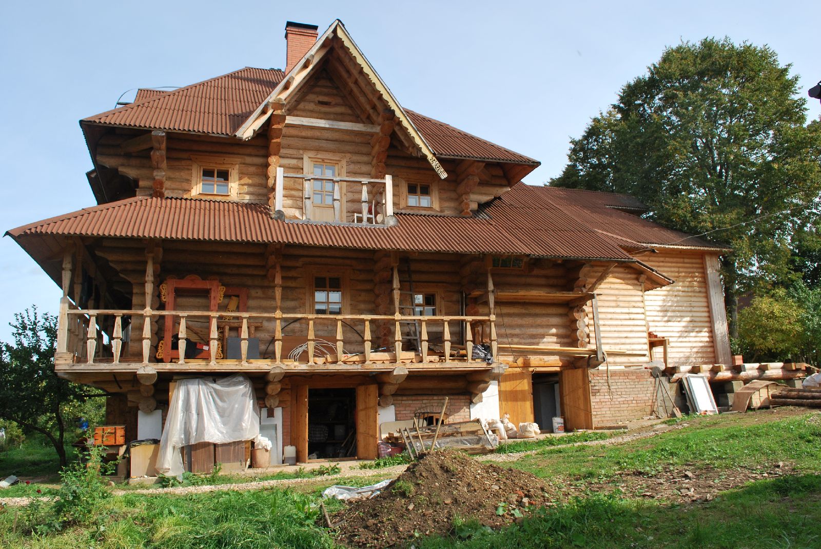
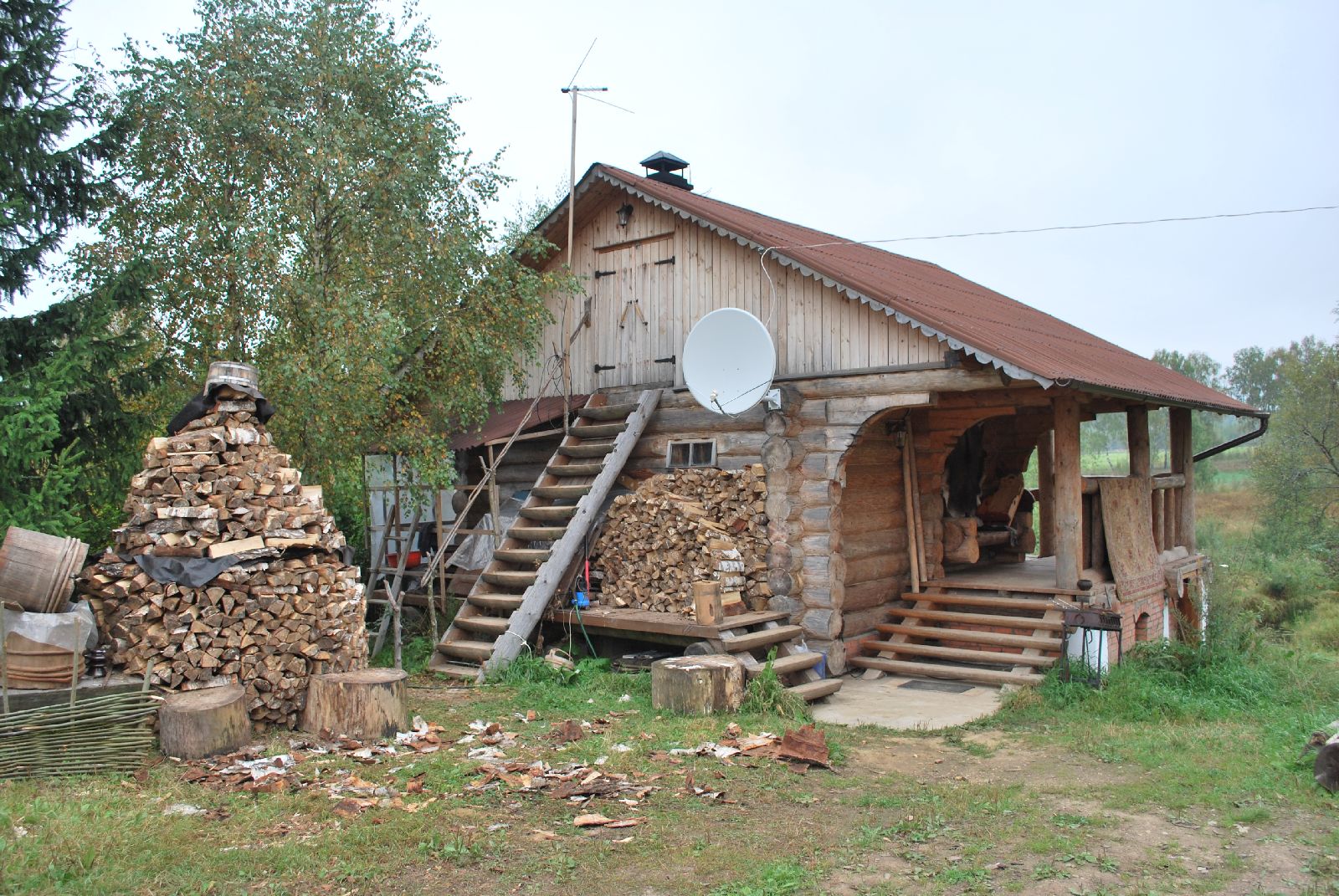
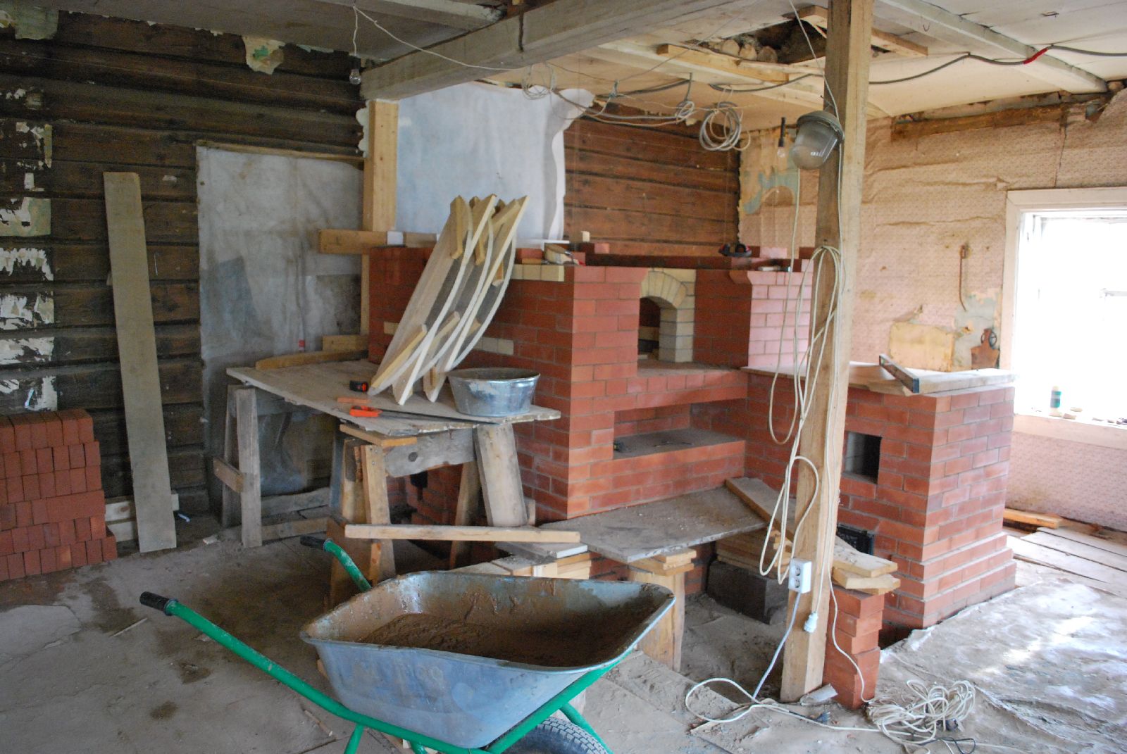
The site.
The new log house has been built around an existing house first built in 1926.
The house was used as a forward divisional command post in the fascist assault on Moscow during The Great Patriotic War.
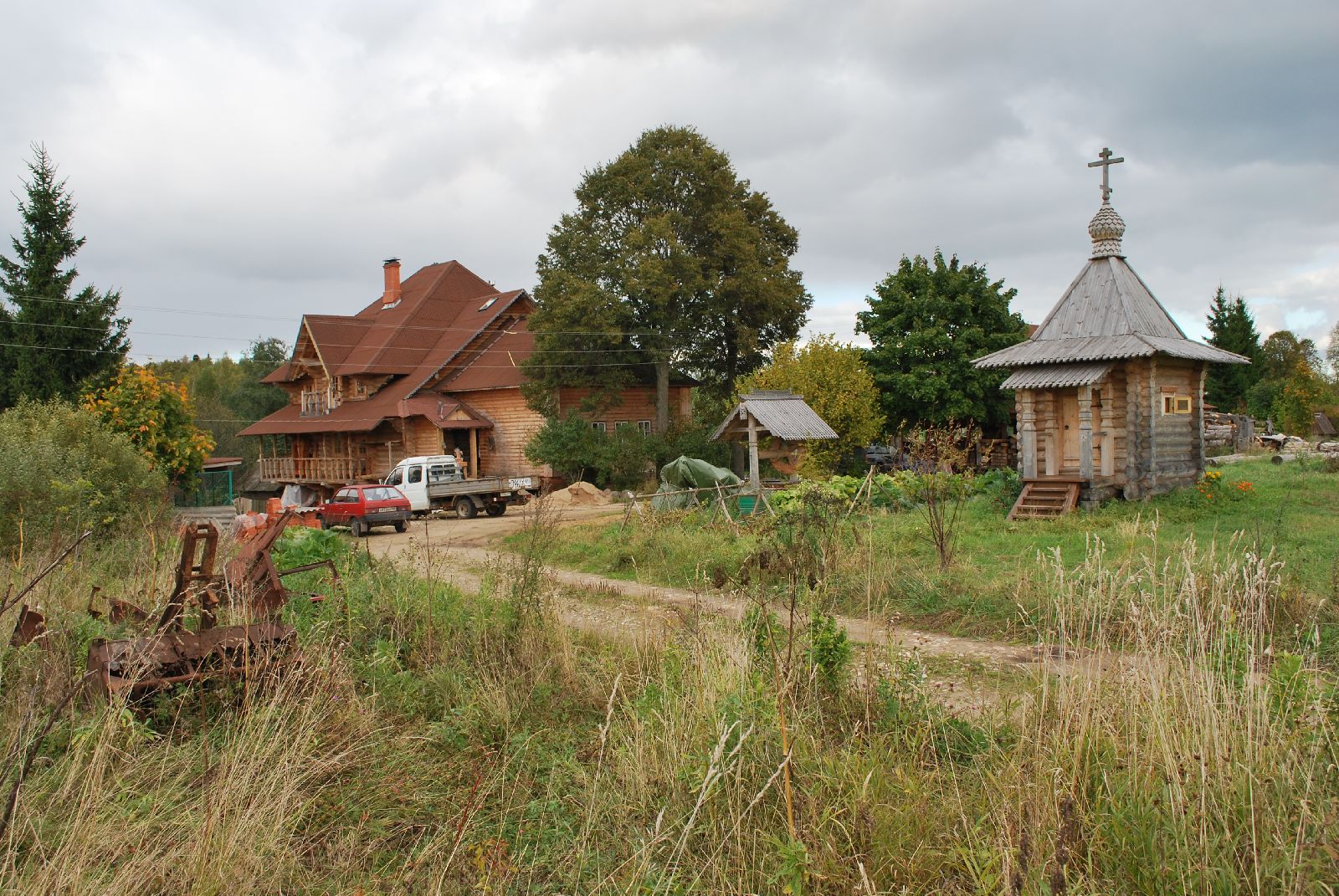
Locals say that it was here that the wounded partisan commander Sergey Solntsev was tortured and then hung from an oak in the garden. The wooden chapel, which bares his name, marks the exact site of the execution.
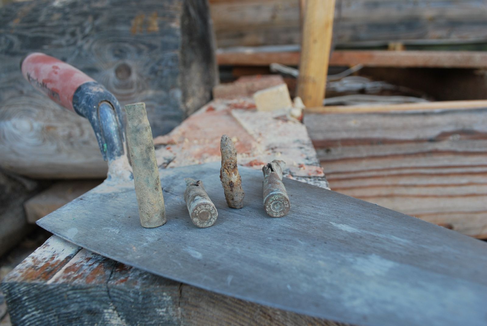
The rusted remains of fascist equipment are still piled to the left of the driveway. They stayed in Agarkovo for three months before being driven back. The countless spent rounds still found today around the house, are testimony to the ferocity of the struggle.
Our quarters above the sauna.
MATERIALS
Facing Brick
Common Belorussian brick, sold in Russia as 'brick for heaters'
Refractory Brick
Bogdanovchi Refractories
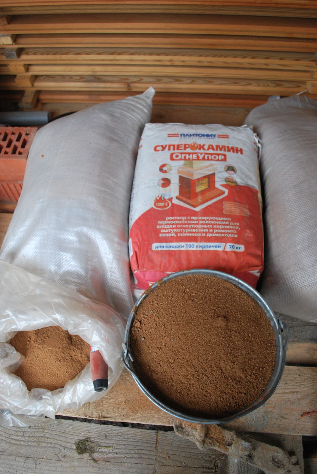
Refractory mortar
Baocheme Refractories. ( Germany)
Common Mortar
7 sand-2 clay-1 Portland
Gasketing
Basalt mineral wool
Hardware
SVT. and Local Generic
'Dry' Refractory mortar, and dry ground clay, both sold especially for the construction of stoves.
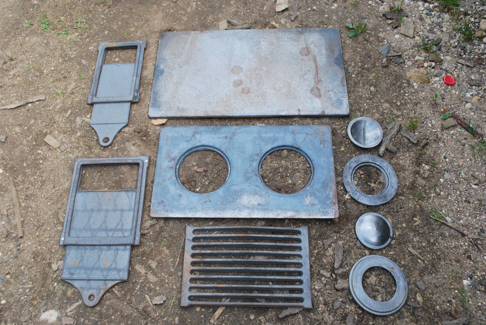
Locally fabricated cast iron cooktops. Dampers and grate.
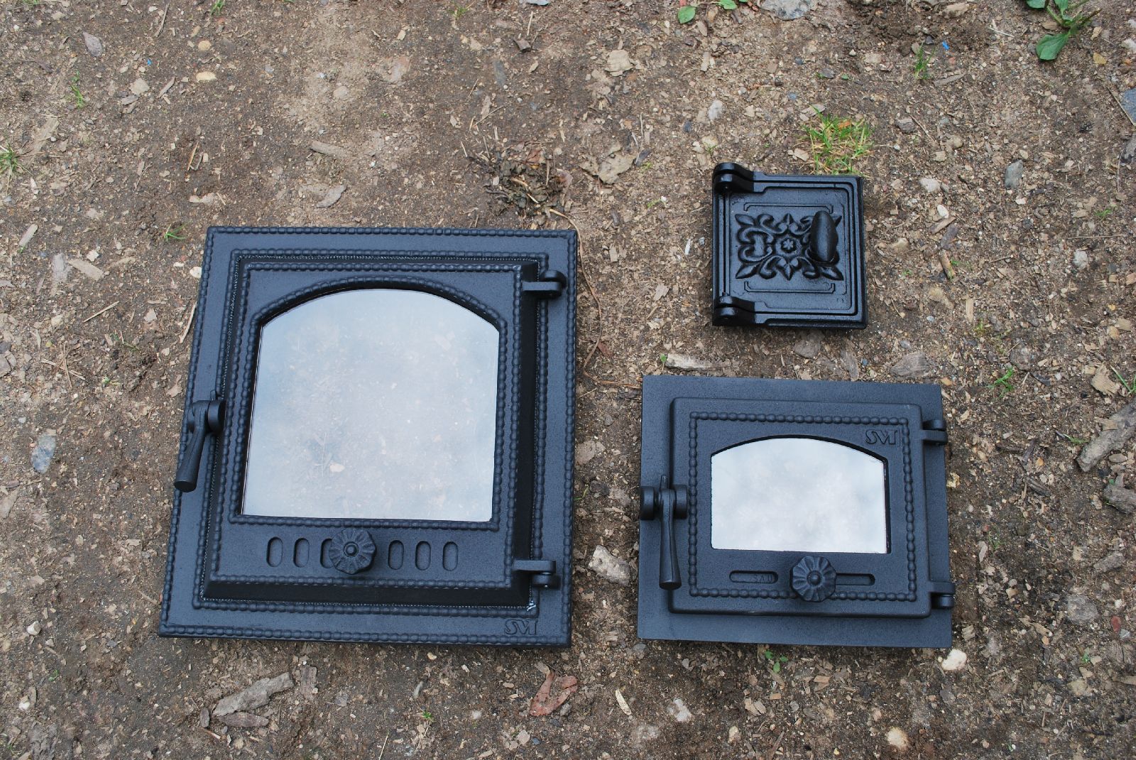
Finnish SVT fire box doors, and Russian fabricated access door.
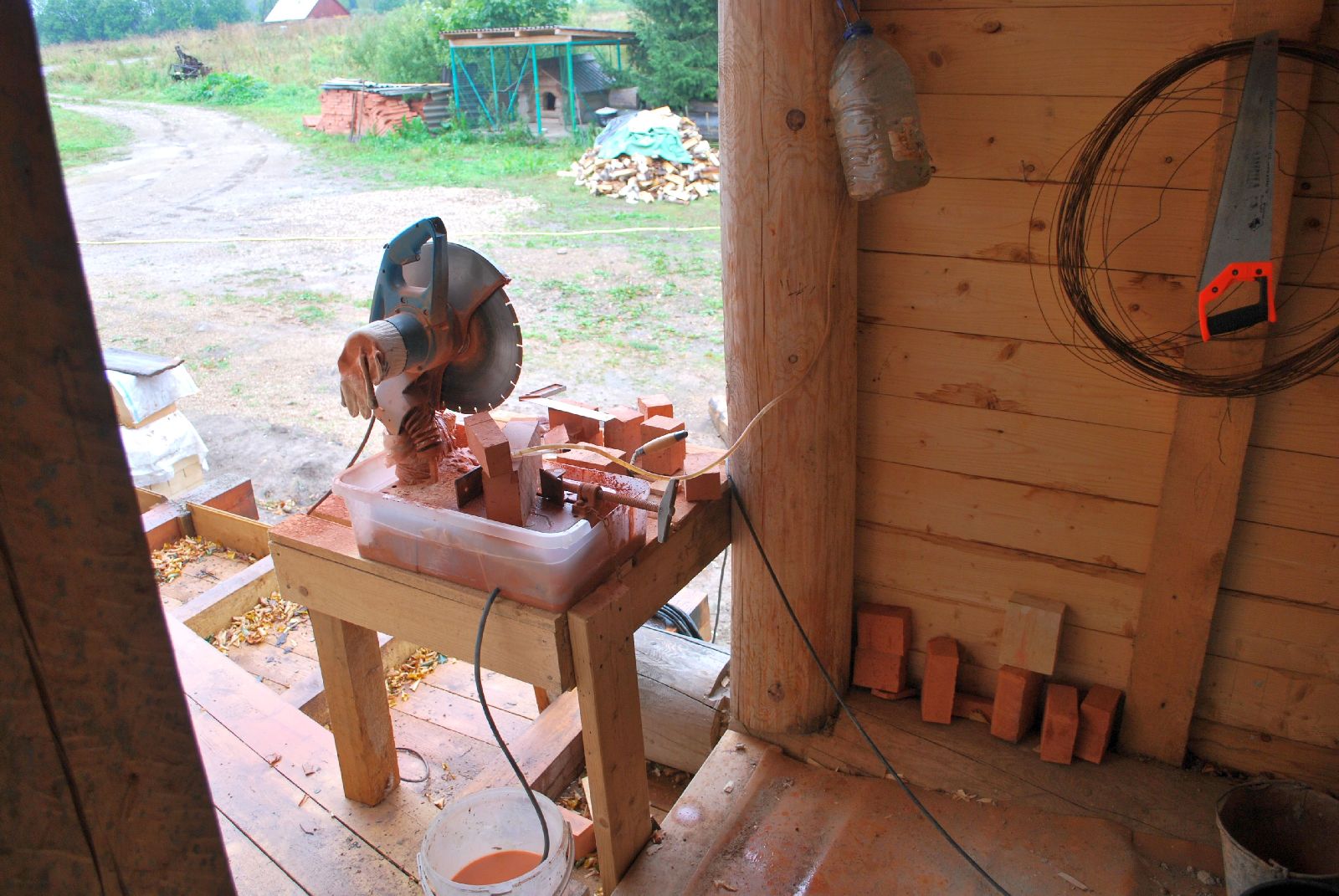
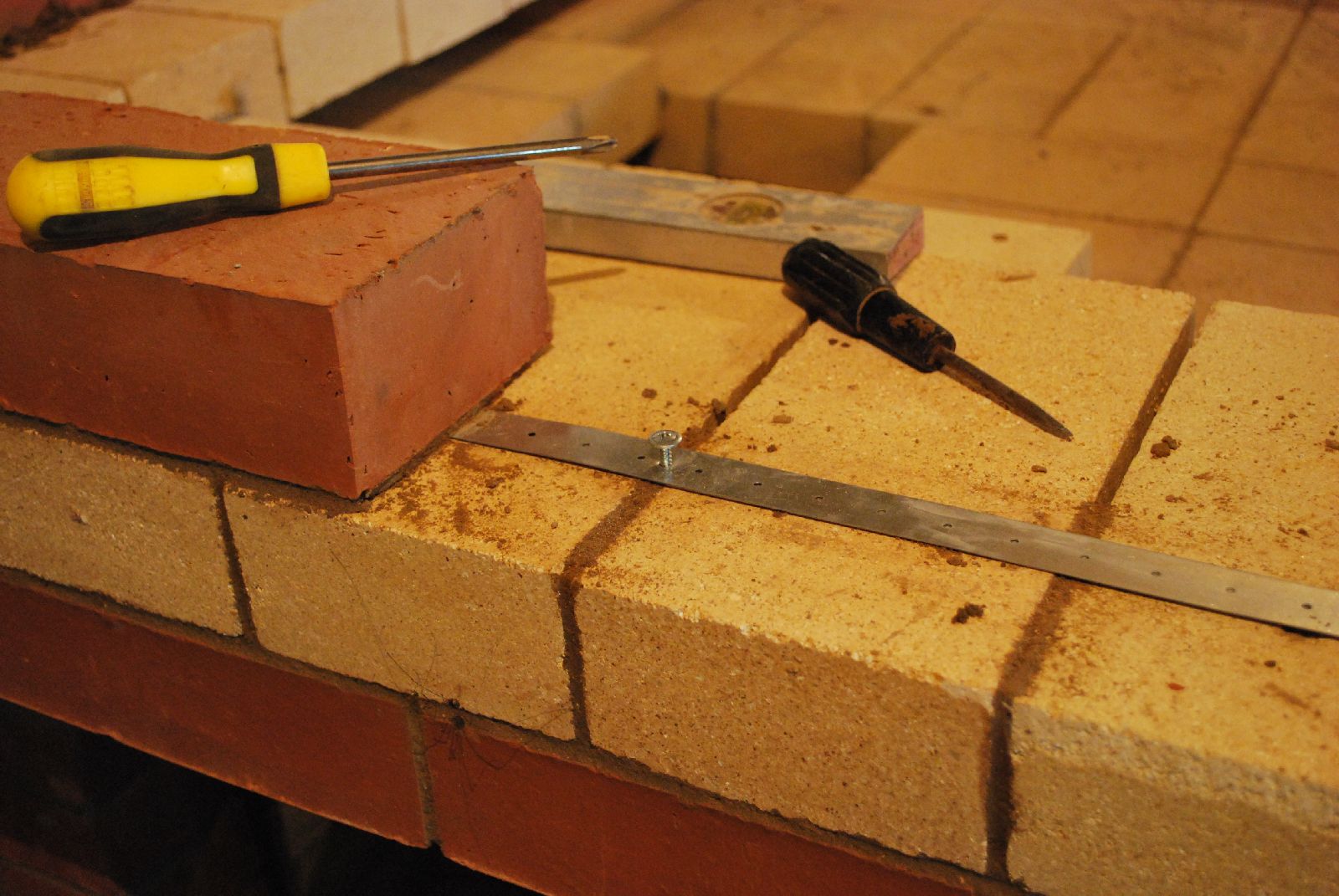
The saw. A Makkitta chop saw with improvised water feed , syphoning from the suspended water bottle at top right.
This saw set up has many limitations, but can get the job done.
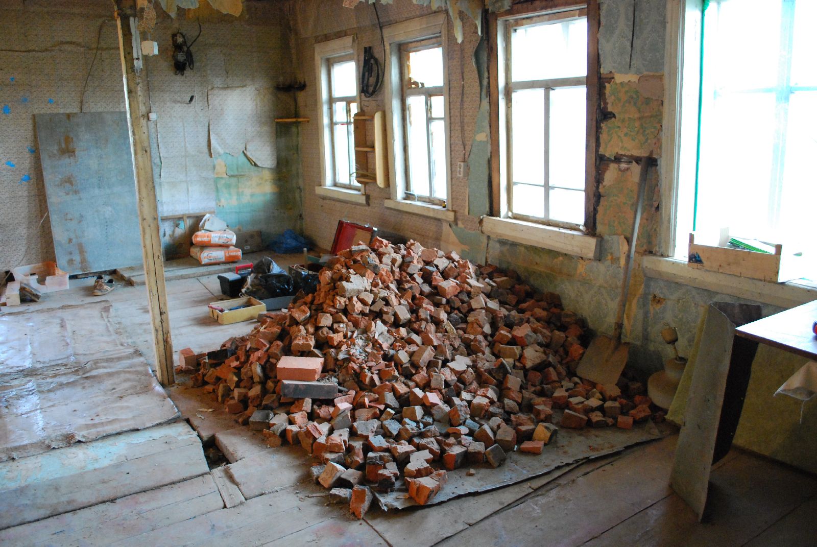
The remains of the house's original oven. Most of the rubble from this demolished oven was used during the pouring of the foundation for the Teplushka. It was in this room that the fascists established their command centre.
Short video of the original oven taken by Youri Vodniev
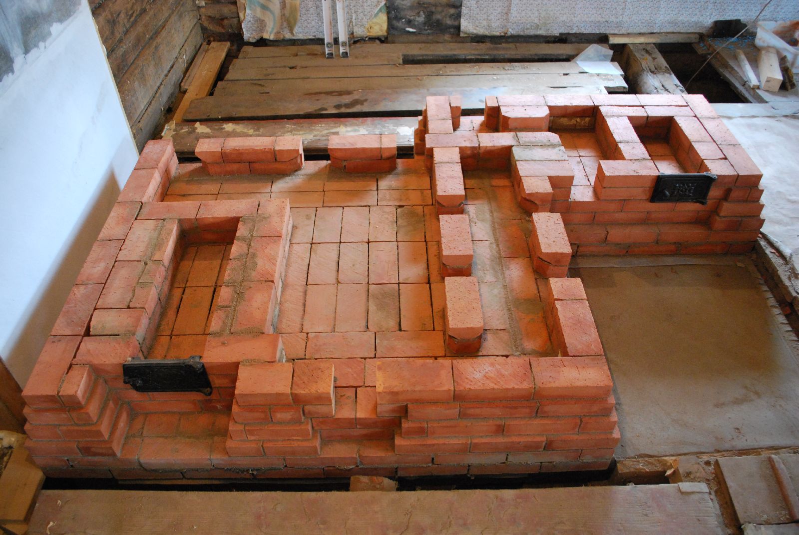
The first 5 courses of the Teplushka and cookstove, at right. From left: the fist 2 courses of the Teplushka's ash box, lower chamber, and manifold. Both Teplushka and cookstove will be served by the same single skin chimney.
Note: The image sequence of the Teplushka and cookstove is irregular and mixed. It reflect though the chronological progression of the project as a whole
The first course is laid onto a polythene vapour barrier. This is generally considered a rule amongst Russian stove builders. The intention of the vapour barrier is to stop the dry stove wicking humidity from the ground and evaporating it into the room.
Both ash box doors are set in clay mortar, and wired into the adjacent bed joints.
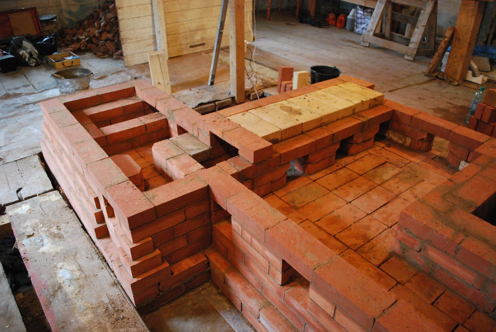
The cookstove from behind. From left: Ashbox, the down channel, chimney connection, and the common chimney. The refractory brick are bridging the Teplushka's manifold, which will also feed into the chimney , at bottom right. Refractory brick are used here only as they are longer than the clay brick and so more suitable to bridge the manifold.
Seen from behind. The lower chamber of the Teplushka, and its three outlets into the manifold.
The cookstove: From left: Ash box, down channel, connection from the down channel to the chimney, bridged with refractory brick, chimney, and behind the chimney, the up channel from the manifold, that will connect to the chimney at about course 25.
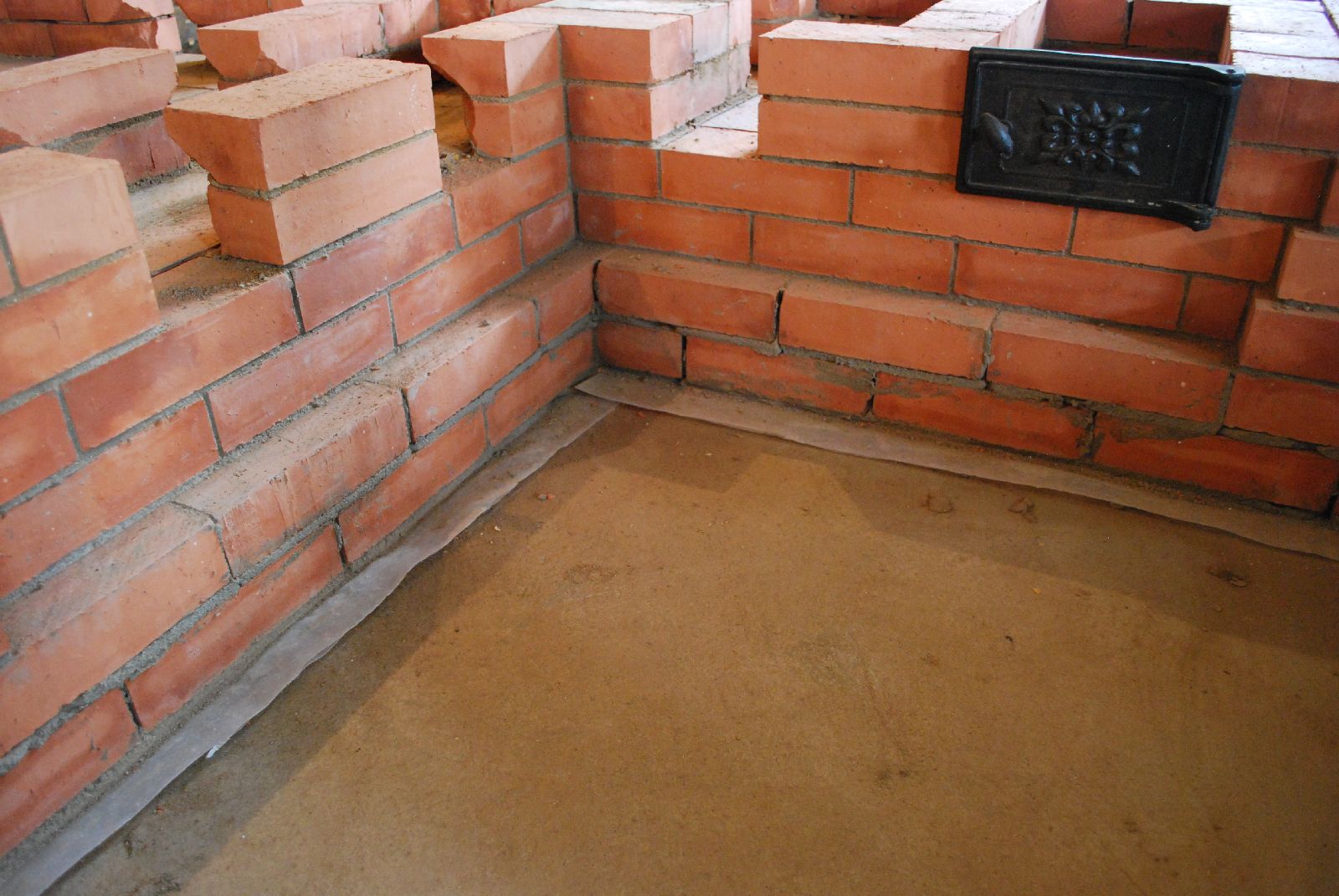
The corbel that will support the refractory brick shiners, used to line the upper portions of the lower chamber.
The head joints of the corbel have been raked out to allow the back of the bricks, that are directly in the smoke path, and so will become hot faster than the portion of the brick in the wall, to expand against them selves. In this situation there is hard mortar on the outer portions of the brick and no mortar on the inner portions. Theoretically the wall should remain stable and not crack.
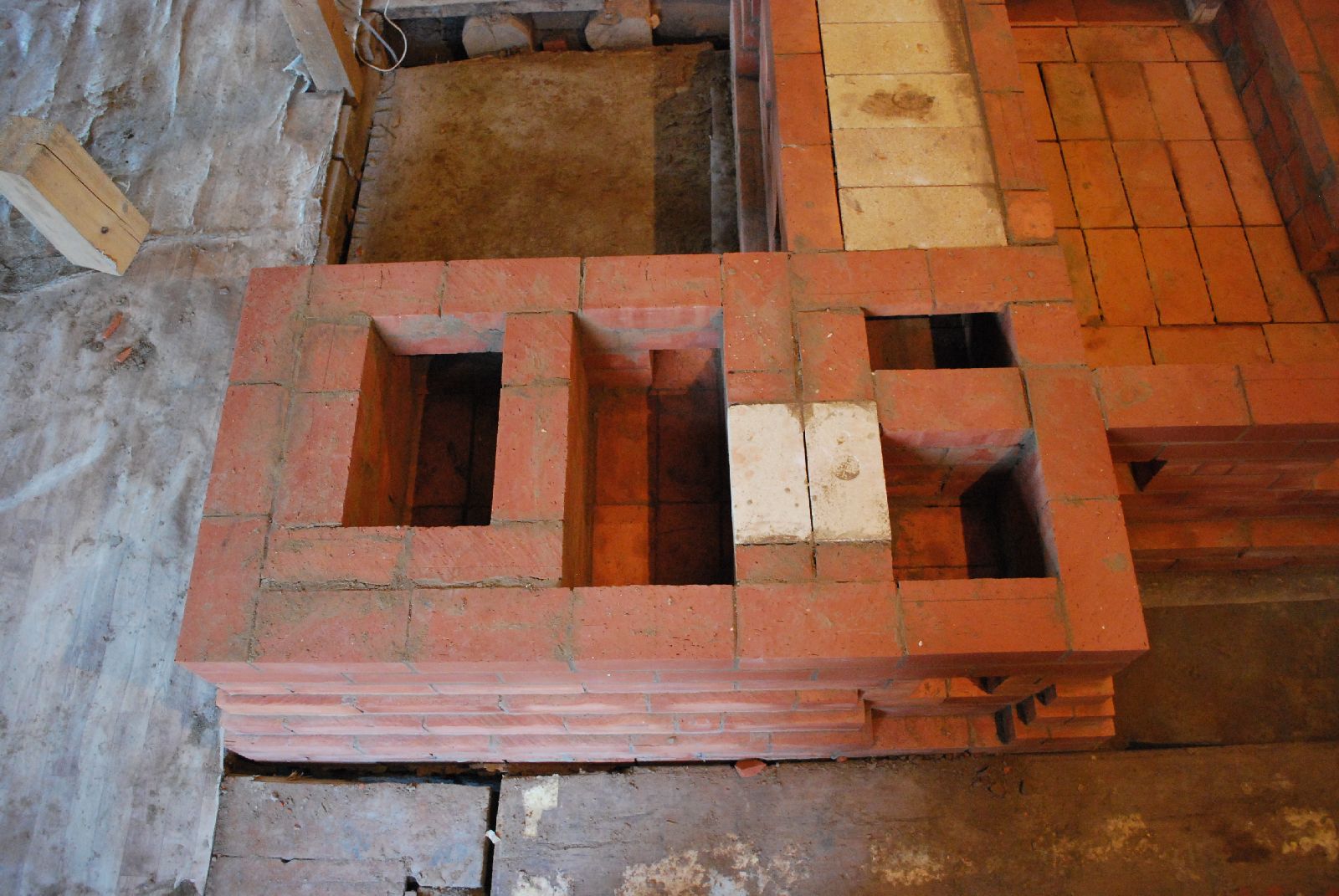
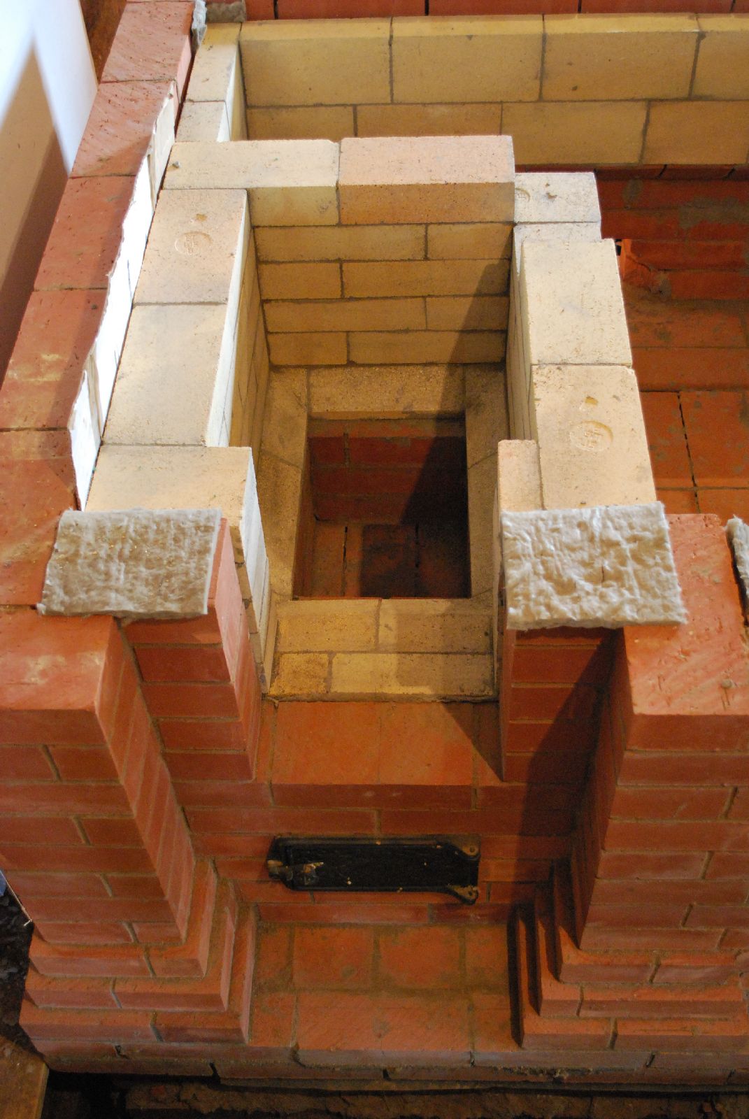
The ash box opening is bridged. From bottom: Ash box, down channel, chimney at right, and Teplushka's connection 'up channel' from the manifold to the left of the chimney.
The corbel that will support the Lining of refractory brick shiners forms the 5th course of the lower chamber. The ash box opening is bridged by three courses and the first two courses of the opening for the firebox laid.
The first course of the cookstove's down channel at left of the ash box.
It only contacts with the wall against the chimney at left.
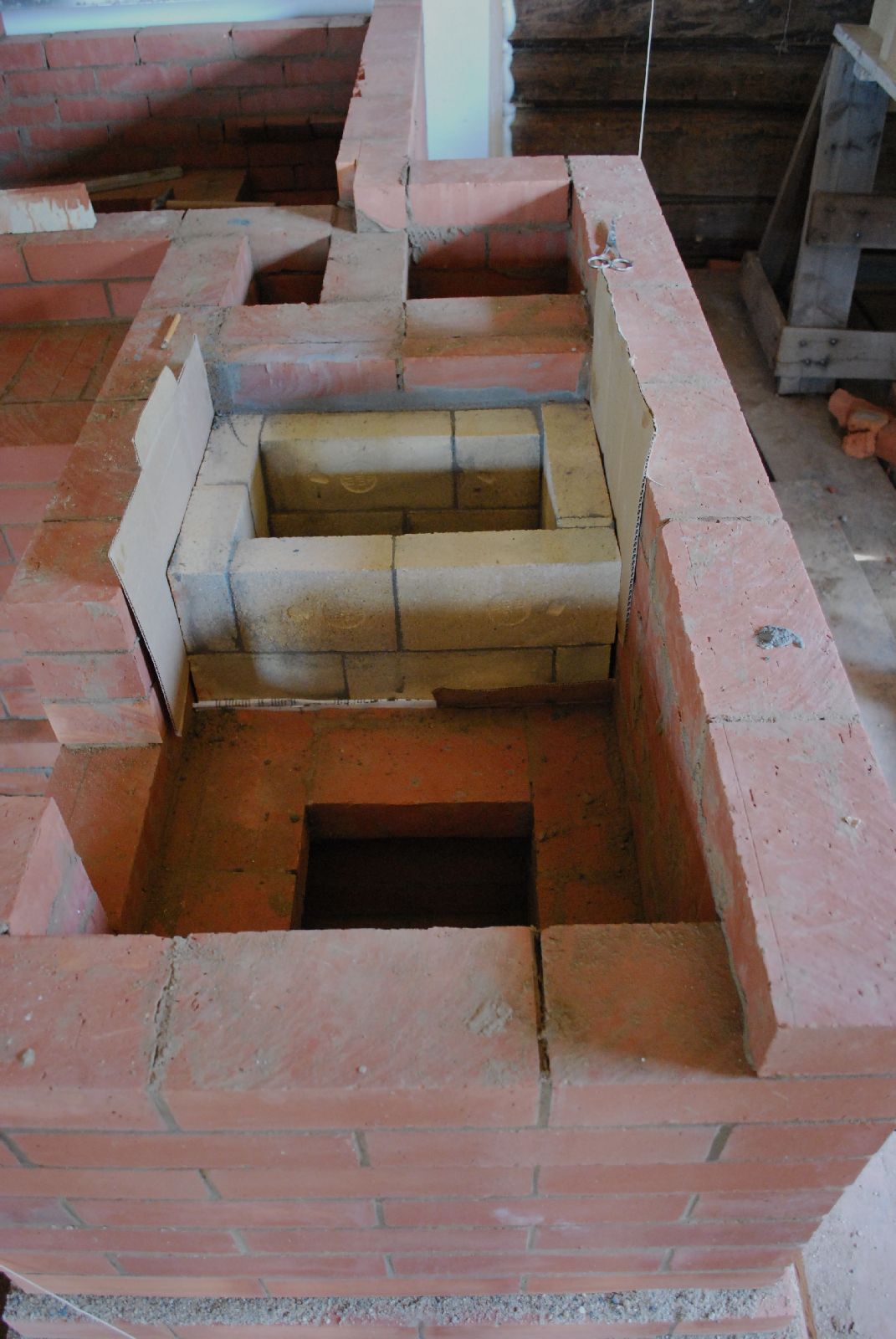
The following courses of the down channel are in refractory brick. The channel is gasketed on three sides with cardboard which will be removed as the work progresses.
Unlike the down channel, which is gasketed only on three sides, the fire box will be completely free floating.
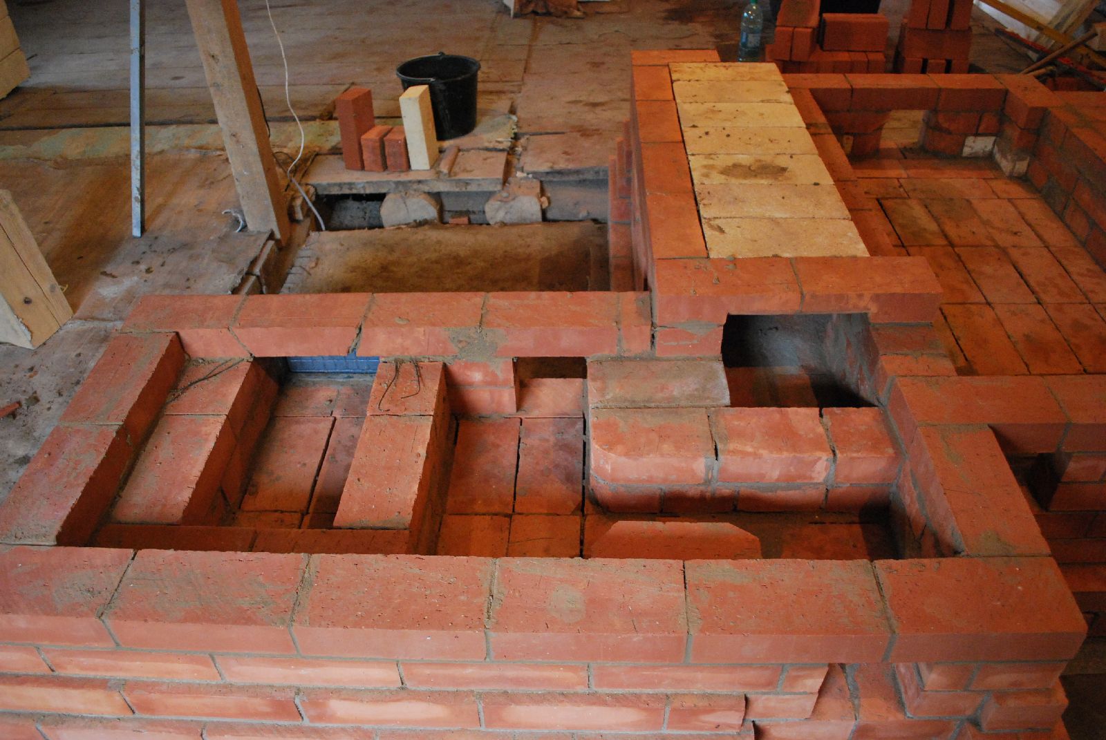
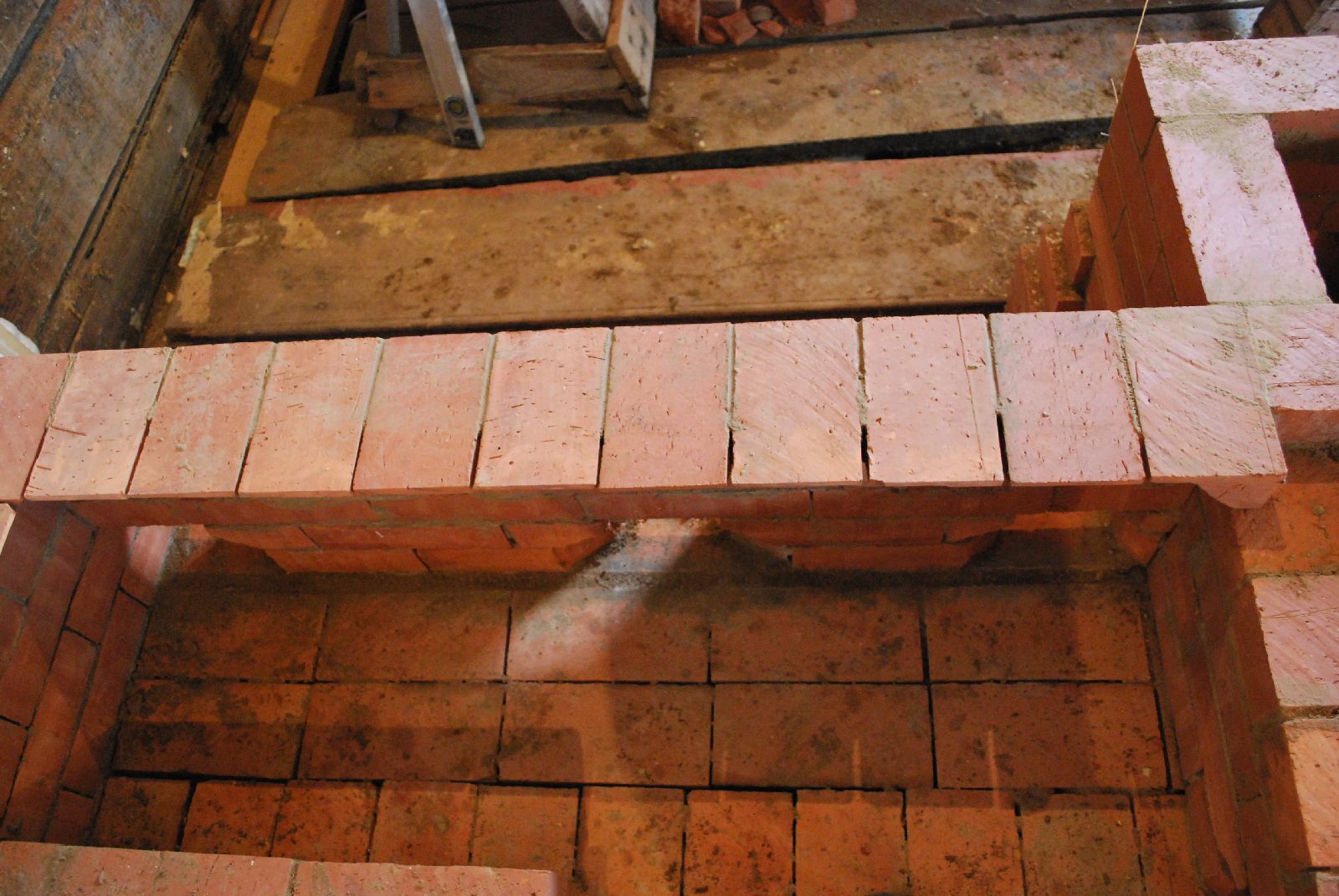
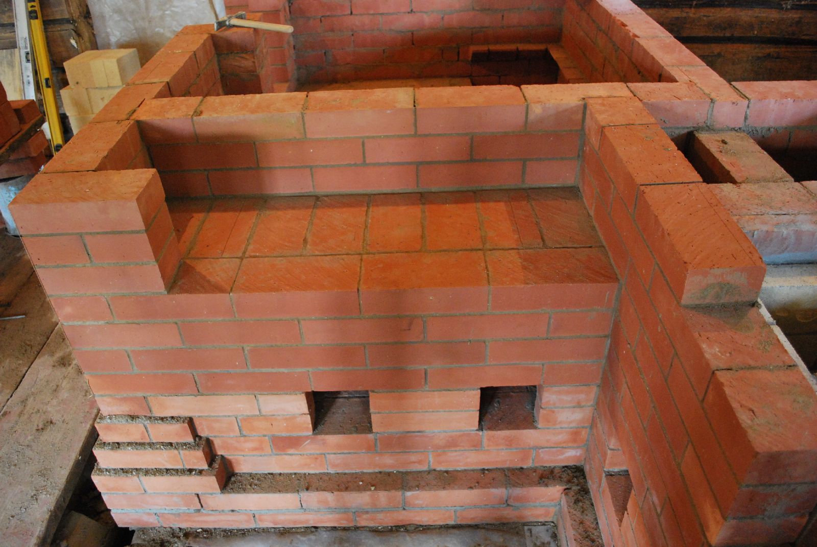
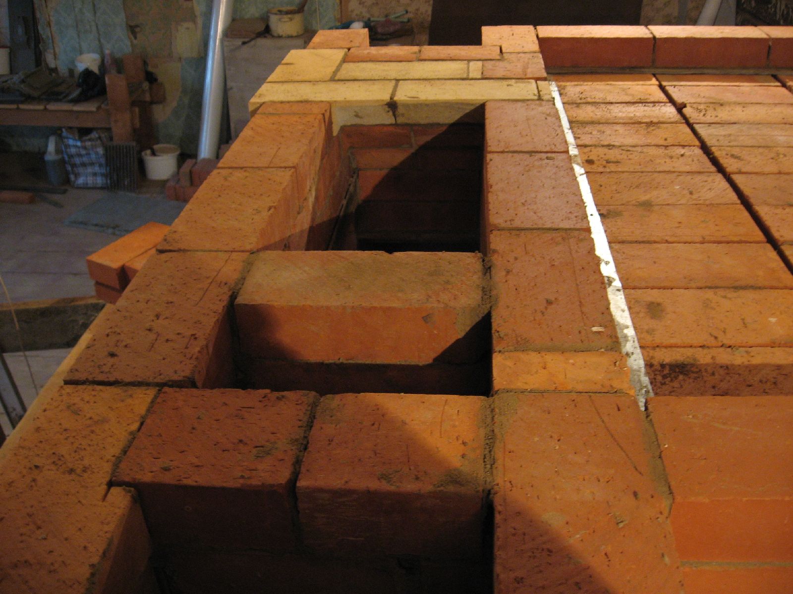
Three courses above the manifold there will be a recess 3 courses high. The Teplushka's bake chamber loading opening will be in this face, above the recess. The recess is a functional aesthetic design feature, and will serve as a shelf on which to place kitchens.
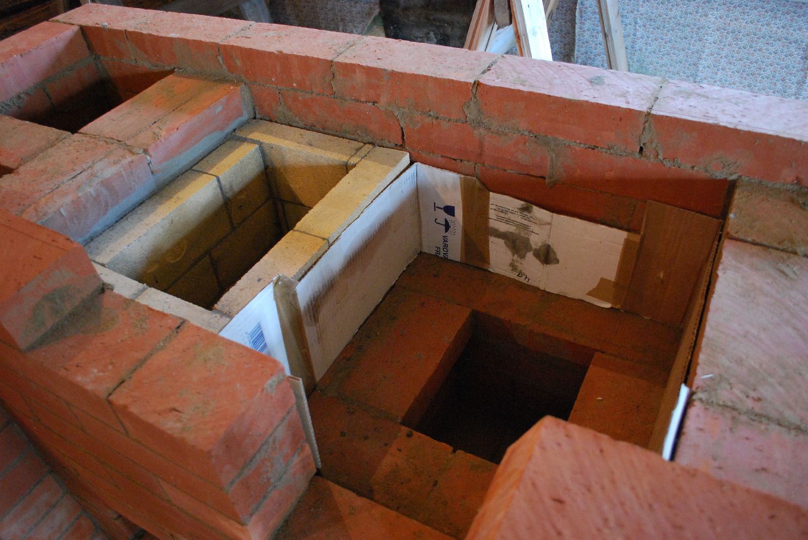
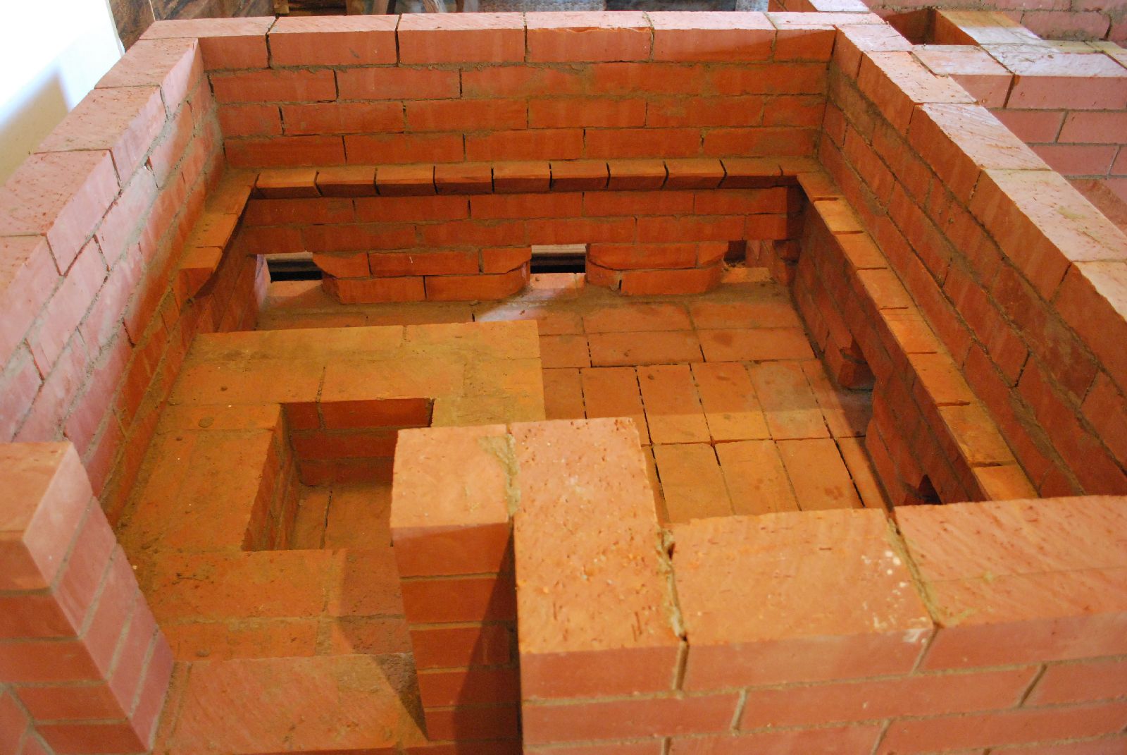
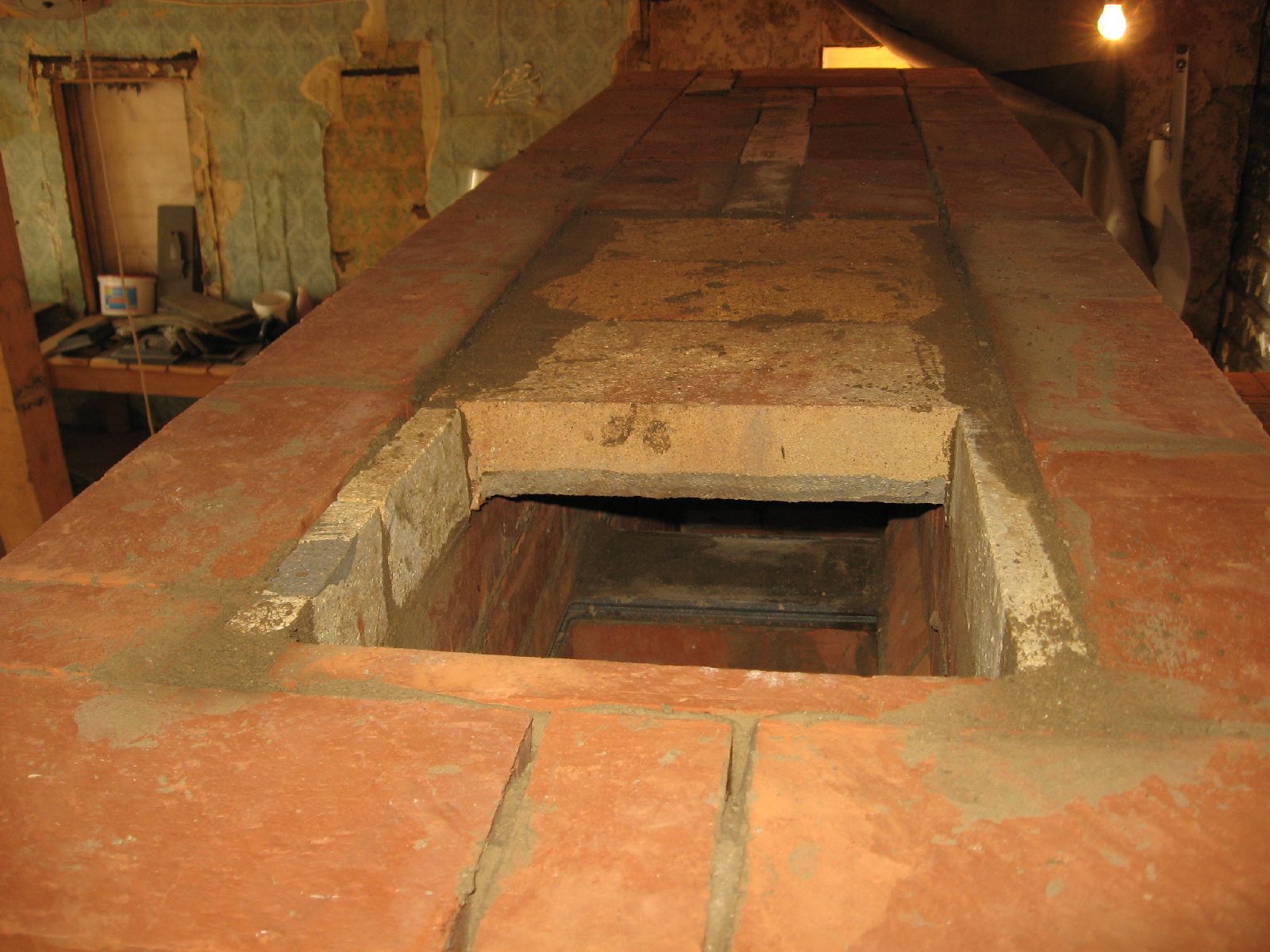
The lower chamber before lining and construction of the fire box. At the bottom of the rear wall are three inspection openings, giving access to the lower chamber, and to the right, two of the three openings into the manifold.
The first two courses of the cookstove's firebox. The cardboard gasket must be pulled up every two courses to avoid becoming permanently trapped in place.
View of the cookstove from the chimney, and Teplushka's chimney connection 'up channel' to the right of the chimney.
Bridging of the cookstove's fire box opening.
The cookstove's fire box and down channel. Once the cardboard gasket has been removed, the free space, between the facing and refractory work, must be protected before laying subsequent courses of the facing.
The first row of the Teplushka's fire box. Basalt wool is used to gasket around the loading opening, and cardboard (here removed) between the sides and facing.
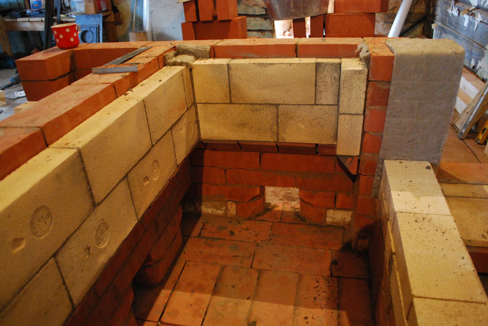
The lining of the upper portions of the lower chamber with refractory brick shiners, laid in refractory mortar.
The lining walls are gasketed at the corners but contact the facing along the length of the lining, to assist transfer.
The two long walls and the short wall (out of view in foreground to right of fire box) are also separated from each by gaskets, with only the short wall to the back right of the fire box being cross bonded into the long rear wall.
Due to the fire box loading opening being recessed into the facing, the exposed strip of facing brick, between the lining and the fire box, cannot lined in this case. Where the fire box loading opening flush with the line of the facing, the lining could be continued to the firebox wall, making this portion of the chamber completely double skinned.
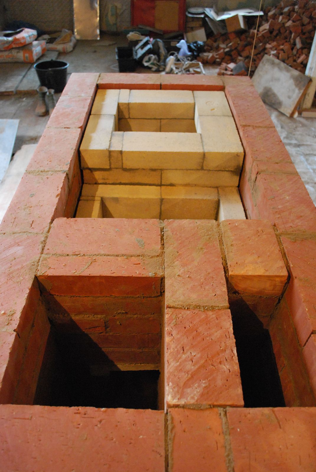
The completed lining and fire box.
The lower chamber will be closed at this point. The lining represents the inner, far, surface of the down channels from the bake chamber to the lower chamber. In the original design of Podgorodnikov these channels are not lined, the inside surface of the facing forming the down channel. It was decided to line these portions as they are areas of high temperature, and the facing here can often fissure in its traditional form.
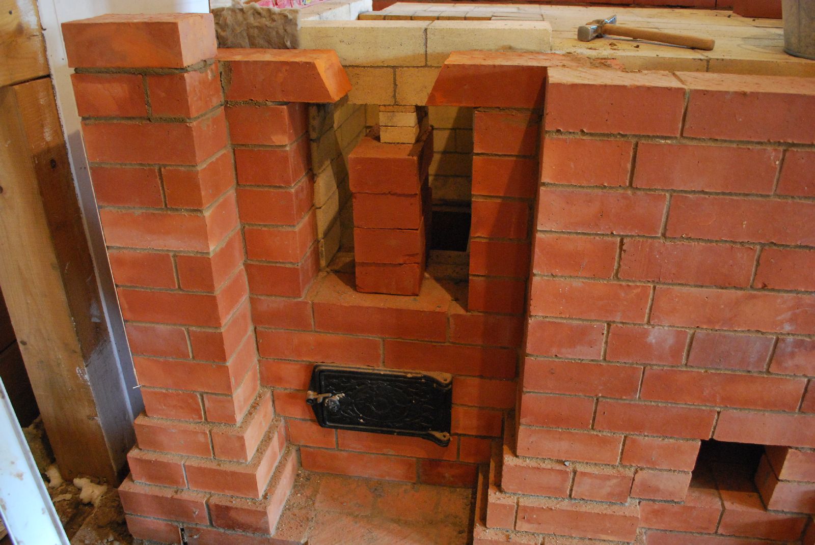
The fire box and recessed loading opening.
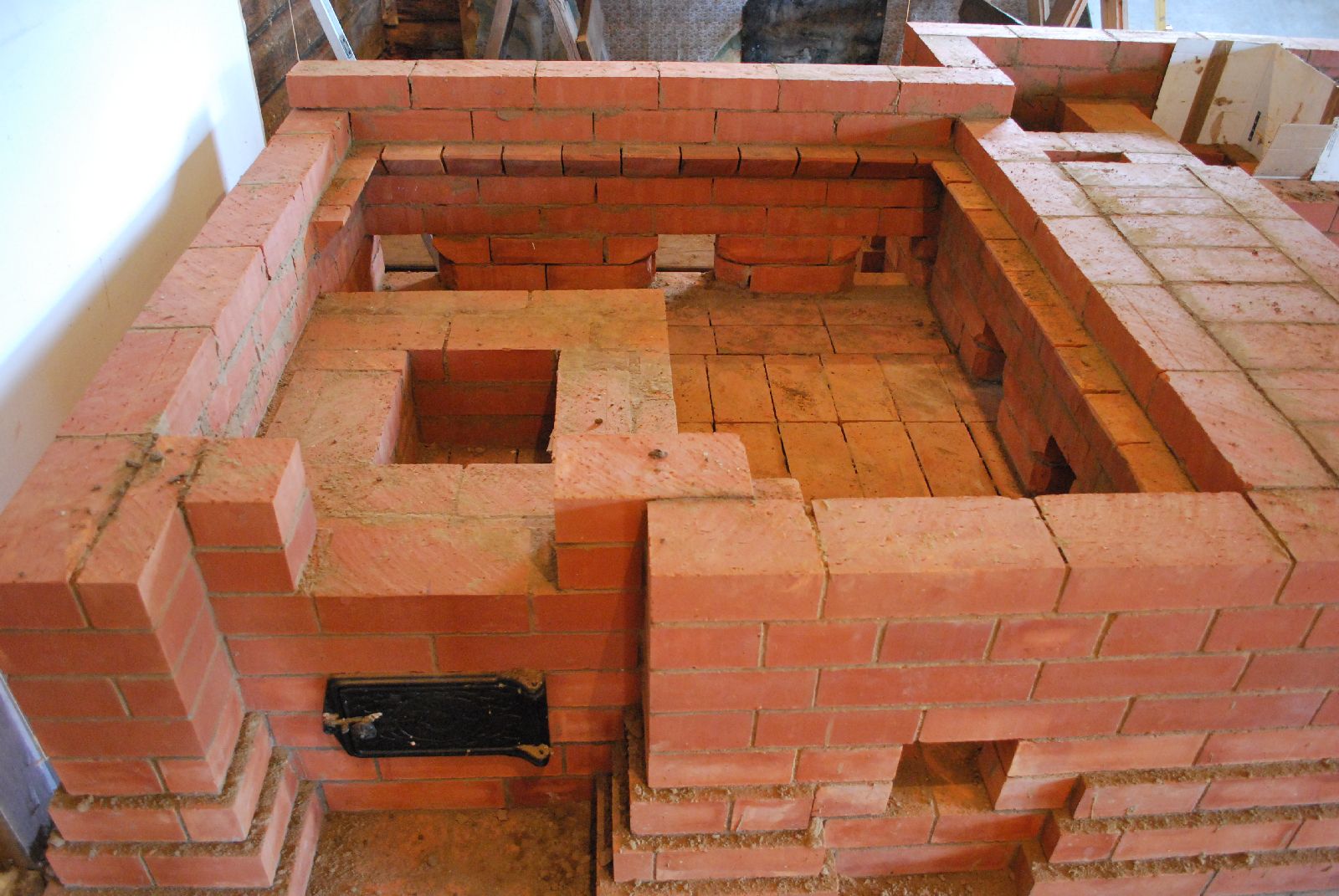
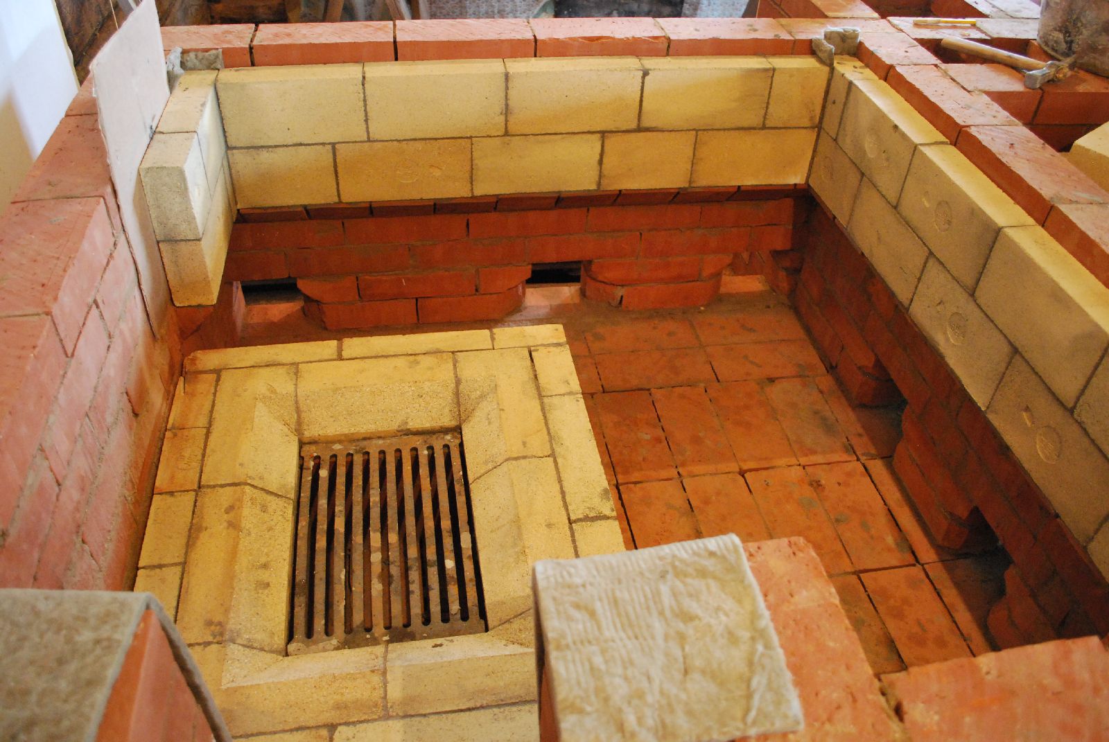
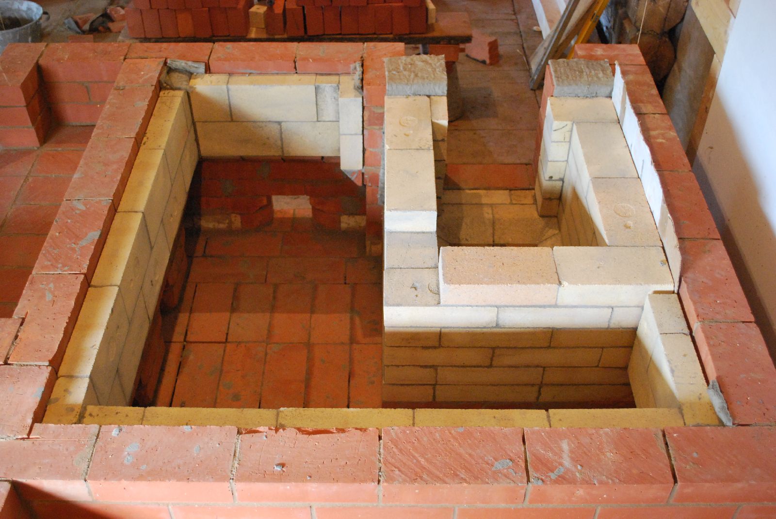
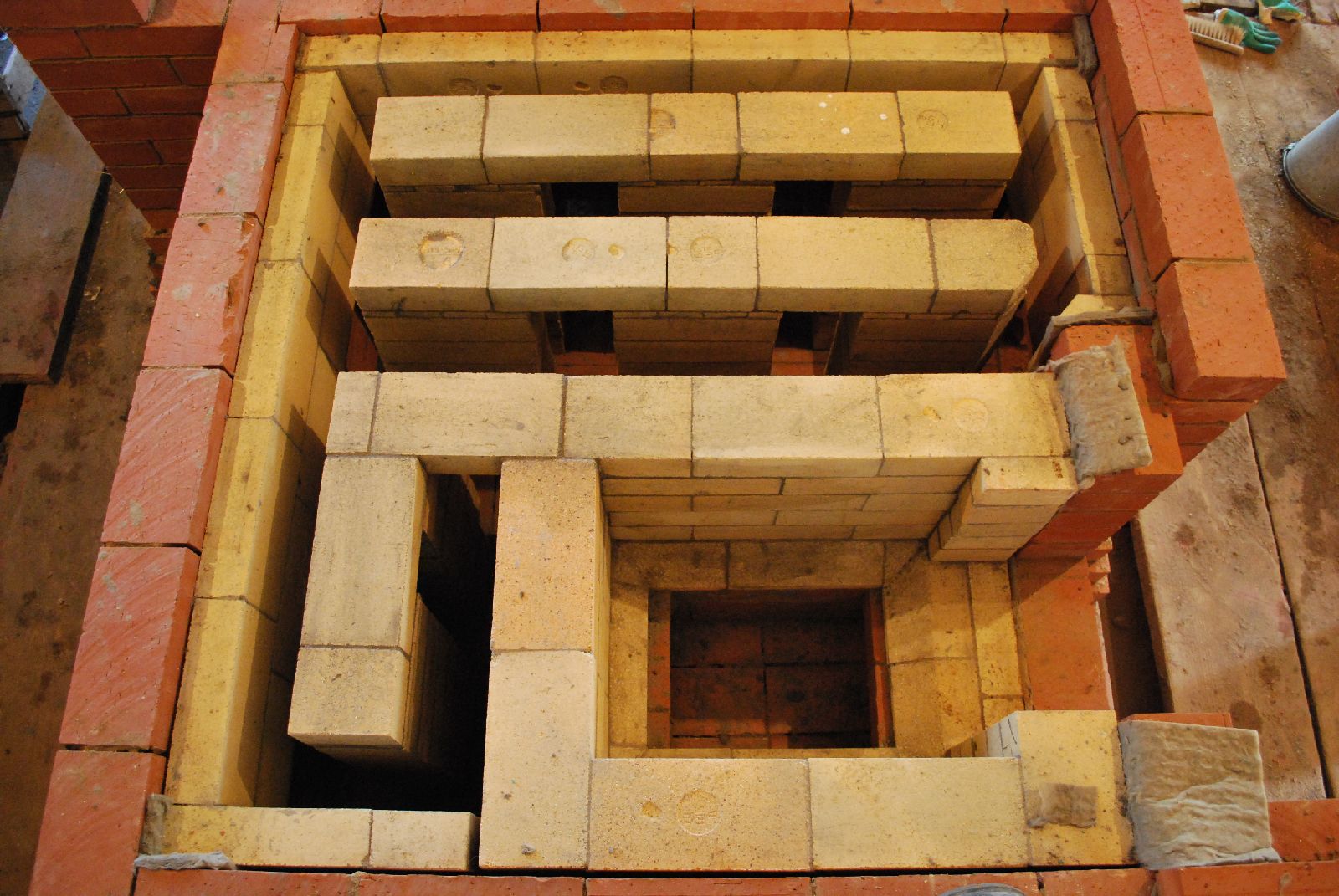
The first courses of 6 of the 8 support columns that will support the vault.
The position of the two columns behind the fire box. The corners of the columns are cut on the first two courses to allow easy access, from the clean out openings, to the area behind the columns.
Two partially built columns. The columns will rise 8 courses before being bridged. Here the corners are cut on ever course of the column to the right to assist flow.
The first course of the 3 and a half courses, necessary to close the lower chamber and form the bake chambers hearth, bridge column to column.
It is at this course that the recess, below the avaloire is also bridged, using 4 pieces of angle bar.
The two columns behind the fire box bridge directly onto the fire box wall.
Before the next course that closes the lower chamber, a half course is laid on to the bridged columns and the portion of the fire box wall on which the next course will rest. This is to arrive at the correct height.
Note: This half course is laid from cross cuts of brick as the saw is incapable of cutting a brick accurately along the entire length of its bead.
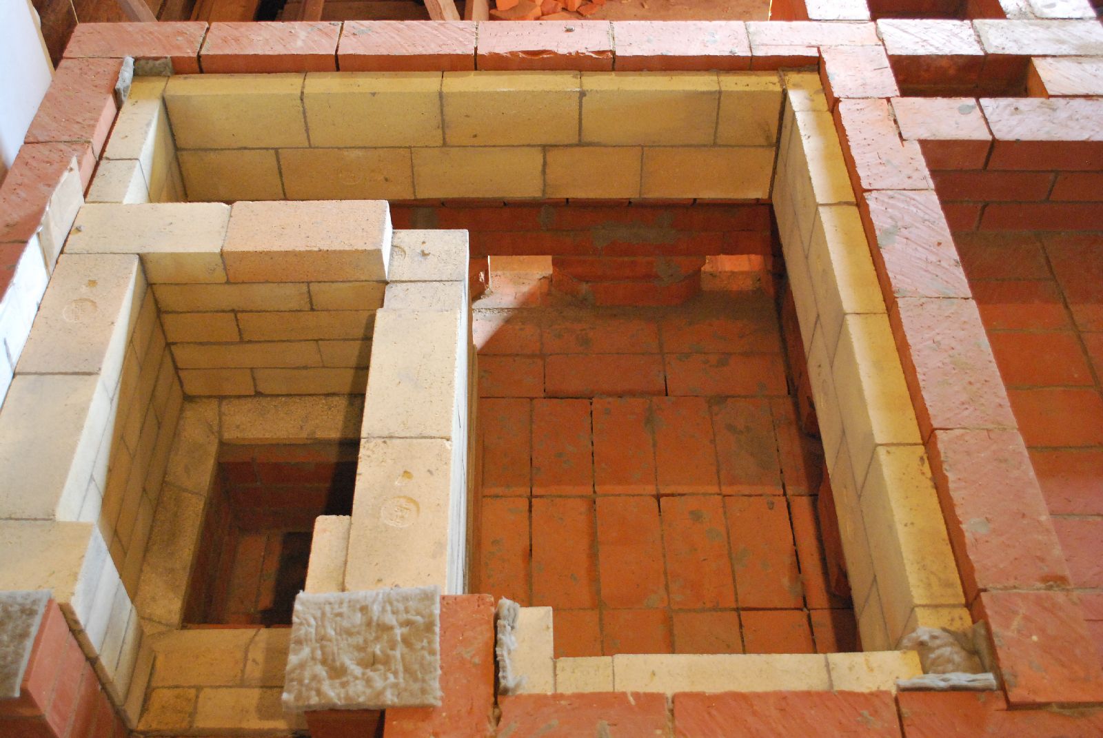
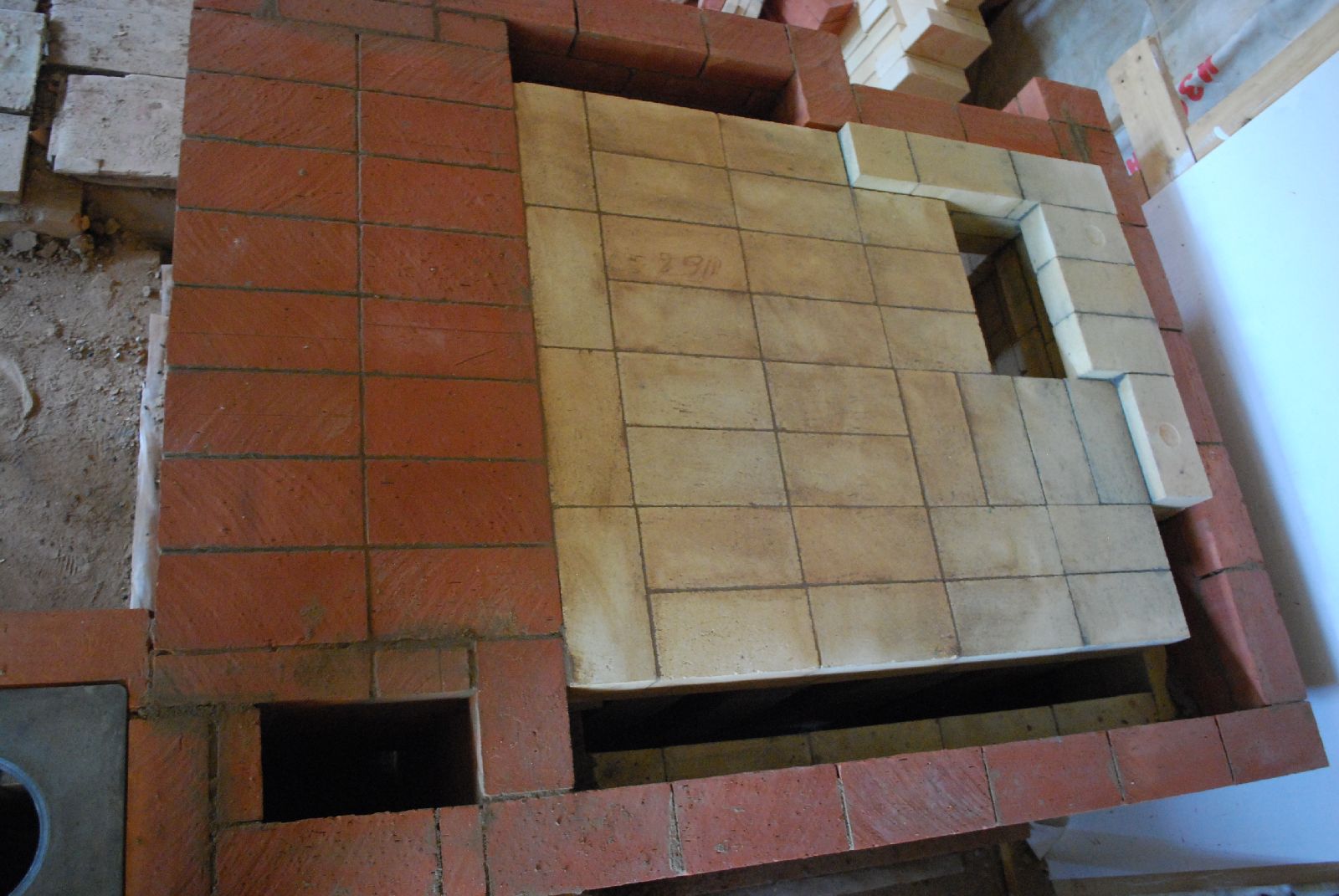
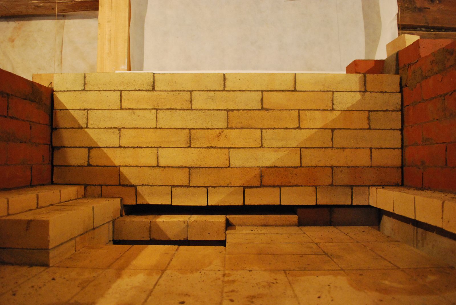
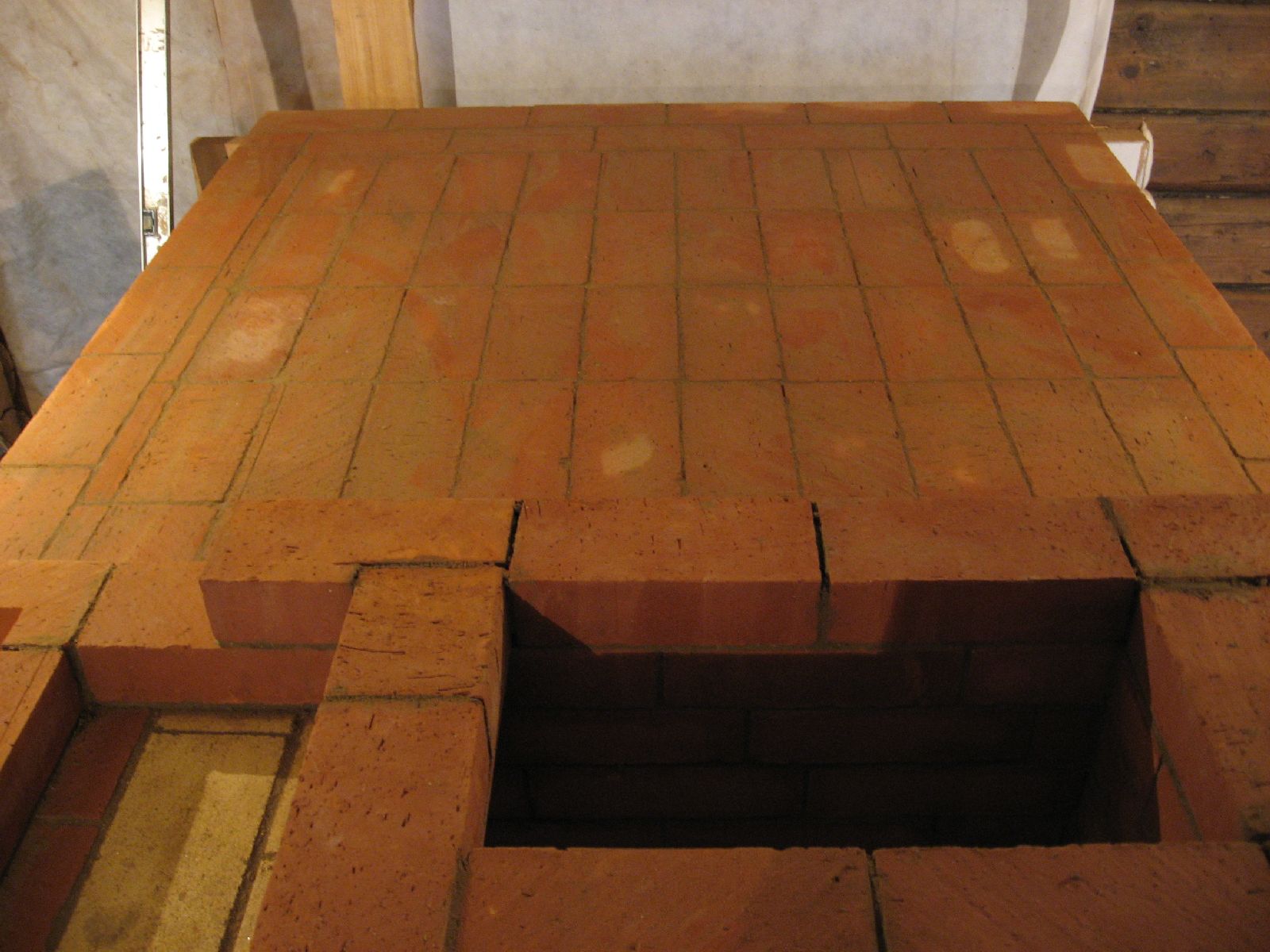
The course that closes the lower chamber. It is on to this that the hearth course will be laid. The rows drawn in pencil indicate the position of the down channels, from the bake chamber to the lower chamber.
Note: It cannot be done here for lack of space but it would be possible to build an independent wall, in the lower chamber, around the fire box, on to which to bridge the hearth. This would avoid having to rest the hearth directly upon the fire box. Though here we are following Podgorodnikov's original plan and bridging on to the fire box, and there have been no accounts of this ever having been a problem.
Another course of crosscut headers are laid onto the fire box wall at right and rear, again to arrive at height. Two courses of full brick are laid on the fire box wall at left, and over the loading opening. It is onto this course that the hearth course will be laid.
Detail of the work around the top of the fire box.
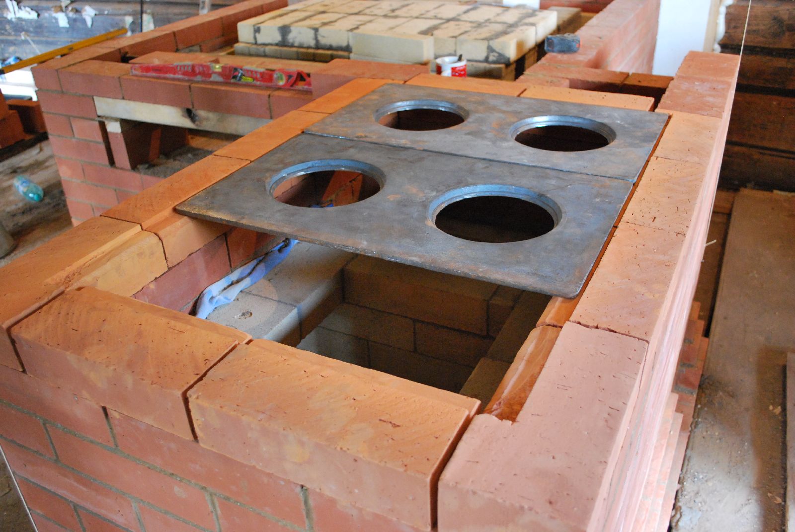
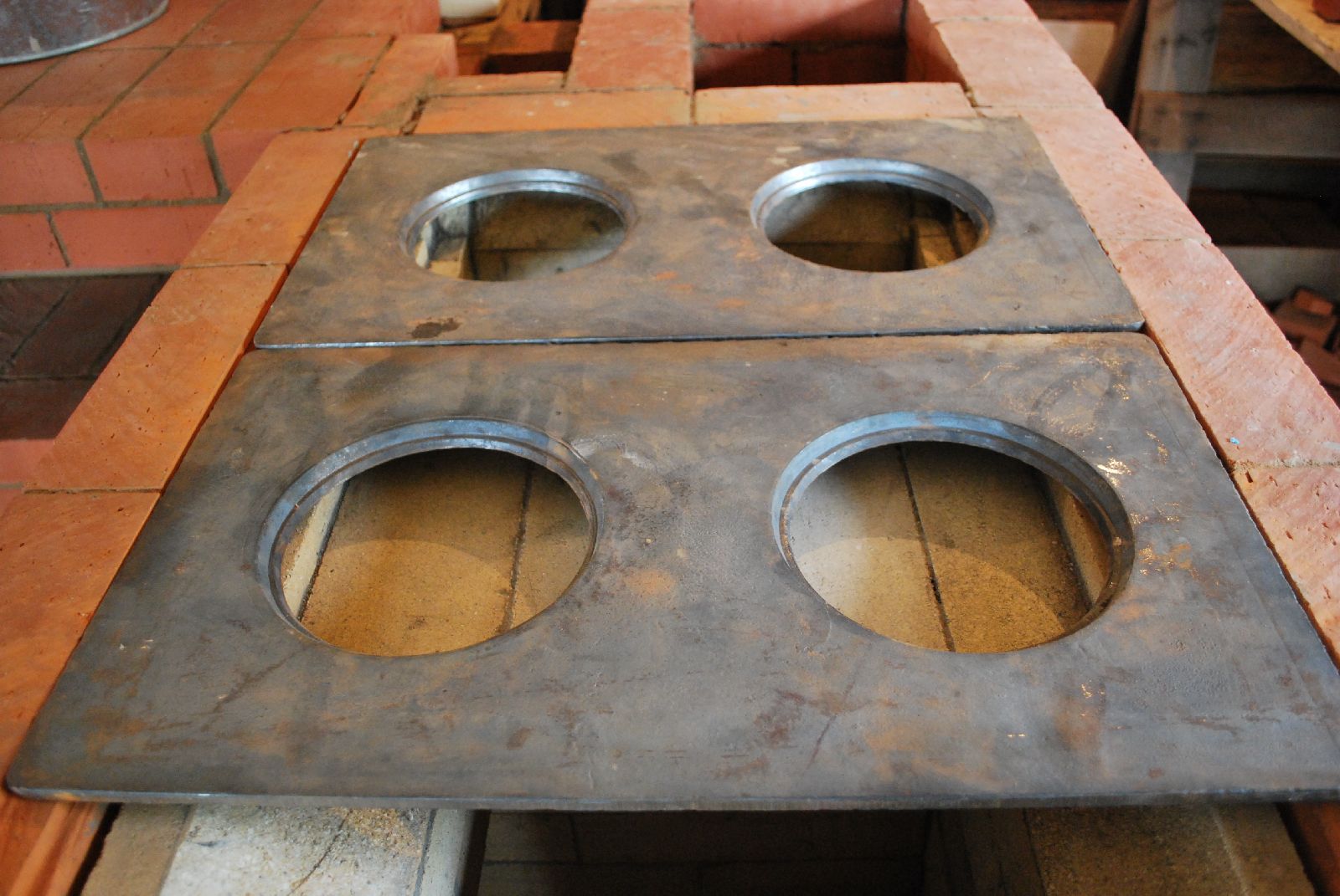
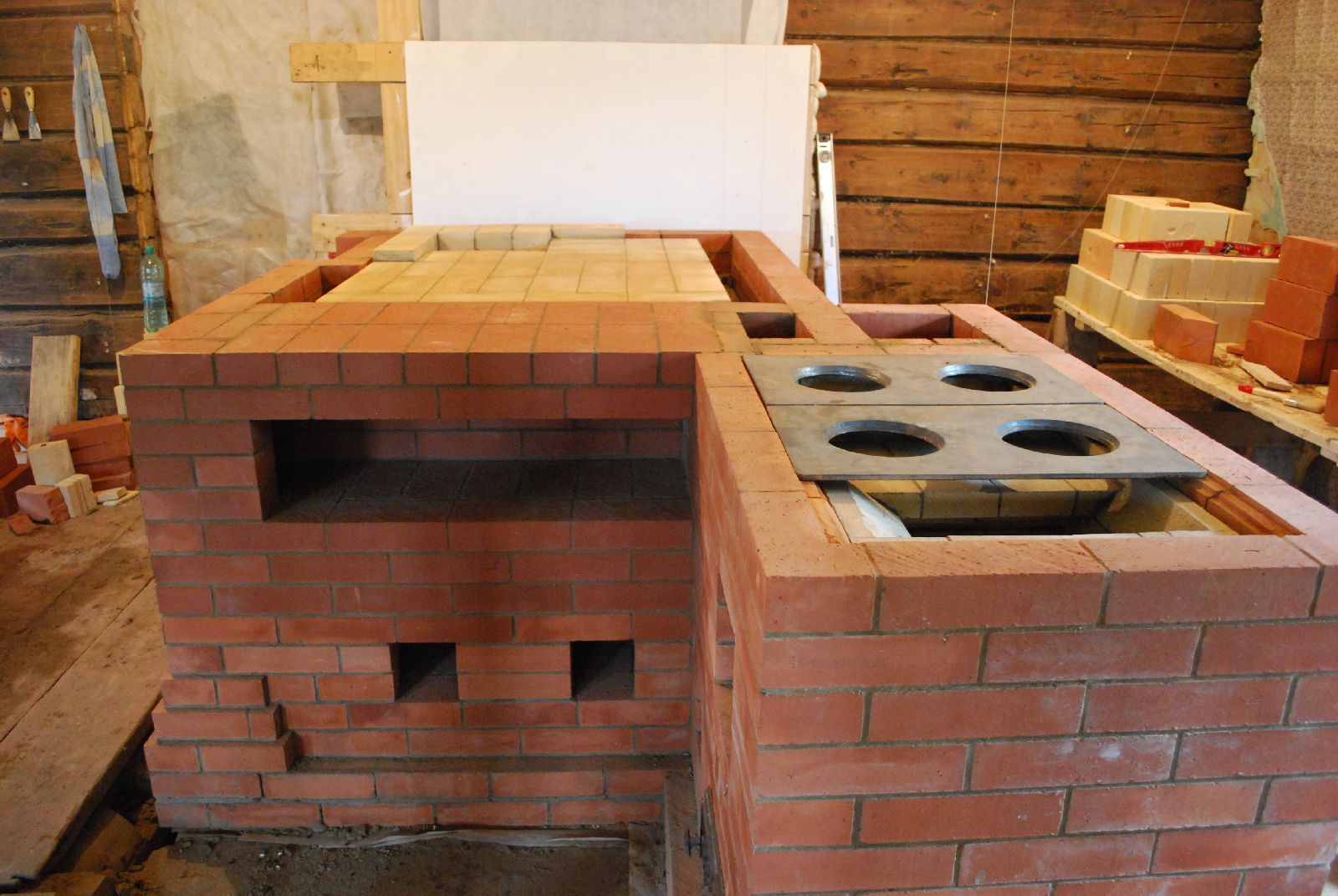
At this point the last course of the cookstove's facing is laid dry and cut out to accept the three cast iron plates that will form the cook top .
Once the last course of facing has been laid, the interior refractory work is brought up to height. The down channel is corbelled in (from the right) to force the flow further along the length of the cook top before descending. The channel is wider below to offer more surface area for captivation.
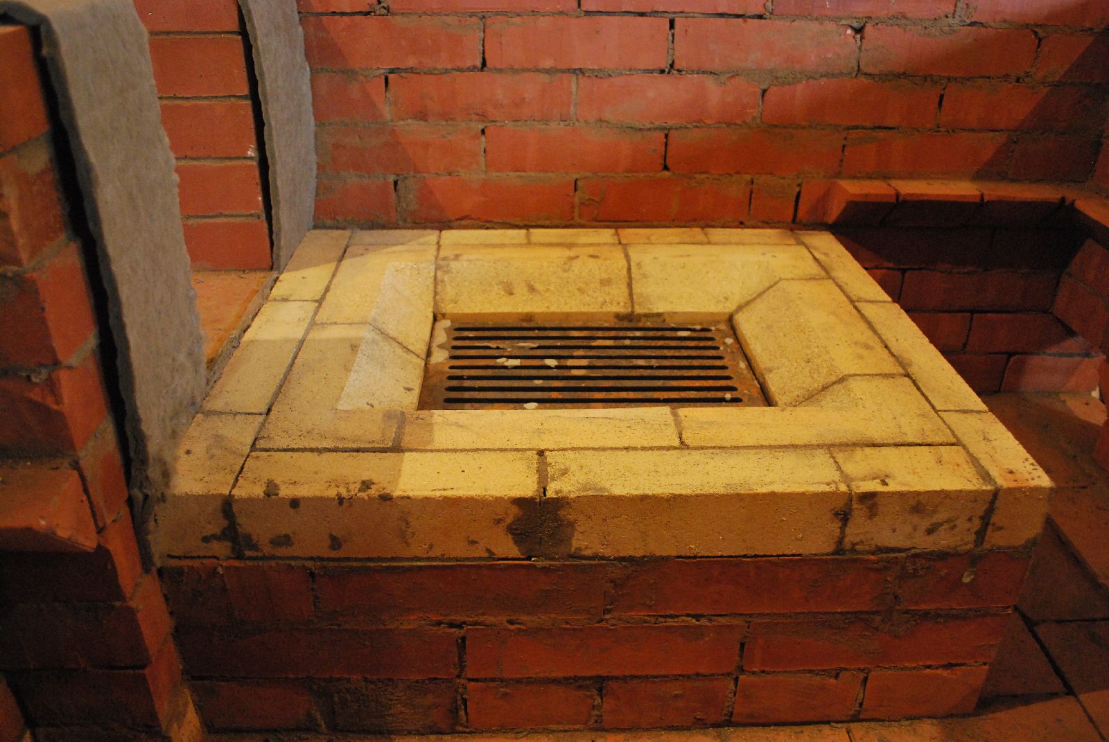
The interior portions of the cookstove finished. The last course of the fire box has been cut back to allow the flame to fully contact the first two hot plates.
Two of the three plates in position. The distance between the bottom of the plates and the refractory work is 4 cm.
Bridging of the fire box loading opening.
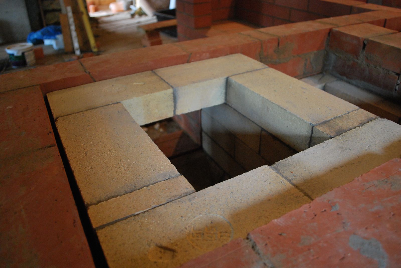
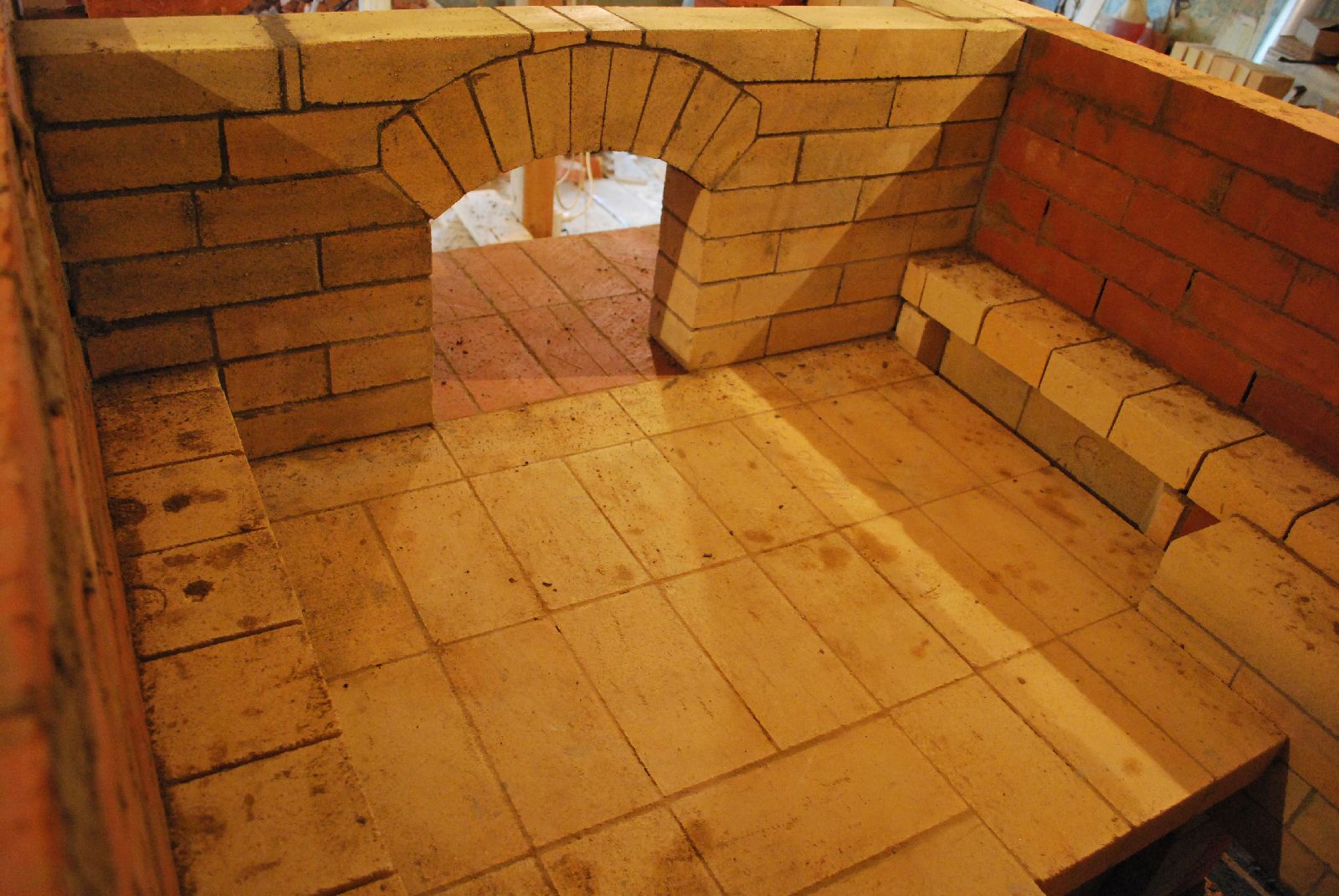
The opening or throat from the fire box ceiling is in the rear left corner of the hearth.
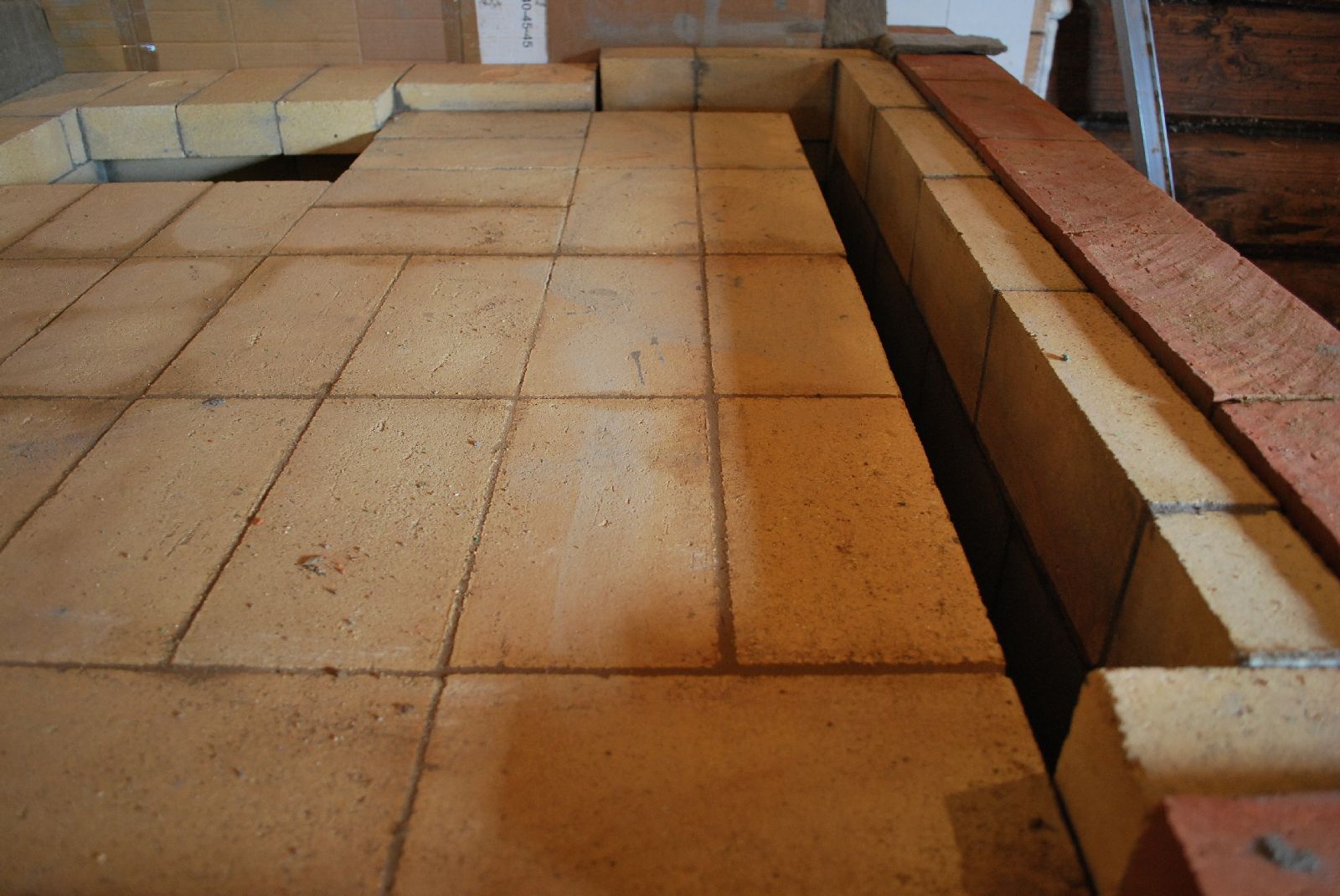
The facing up to hearth level
The hearth course of refractory brick is laid in clay mortar.
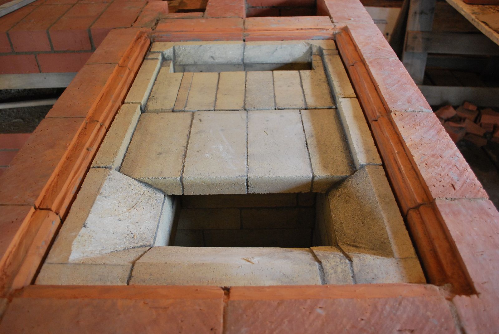
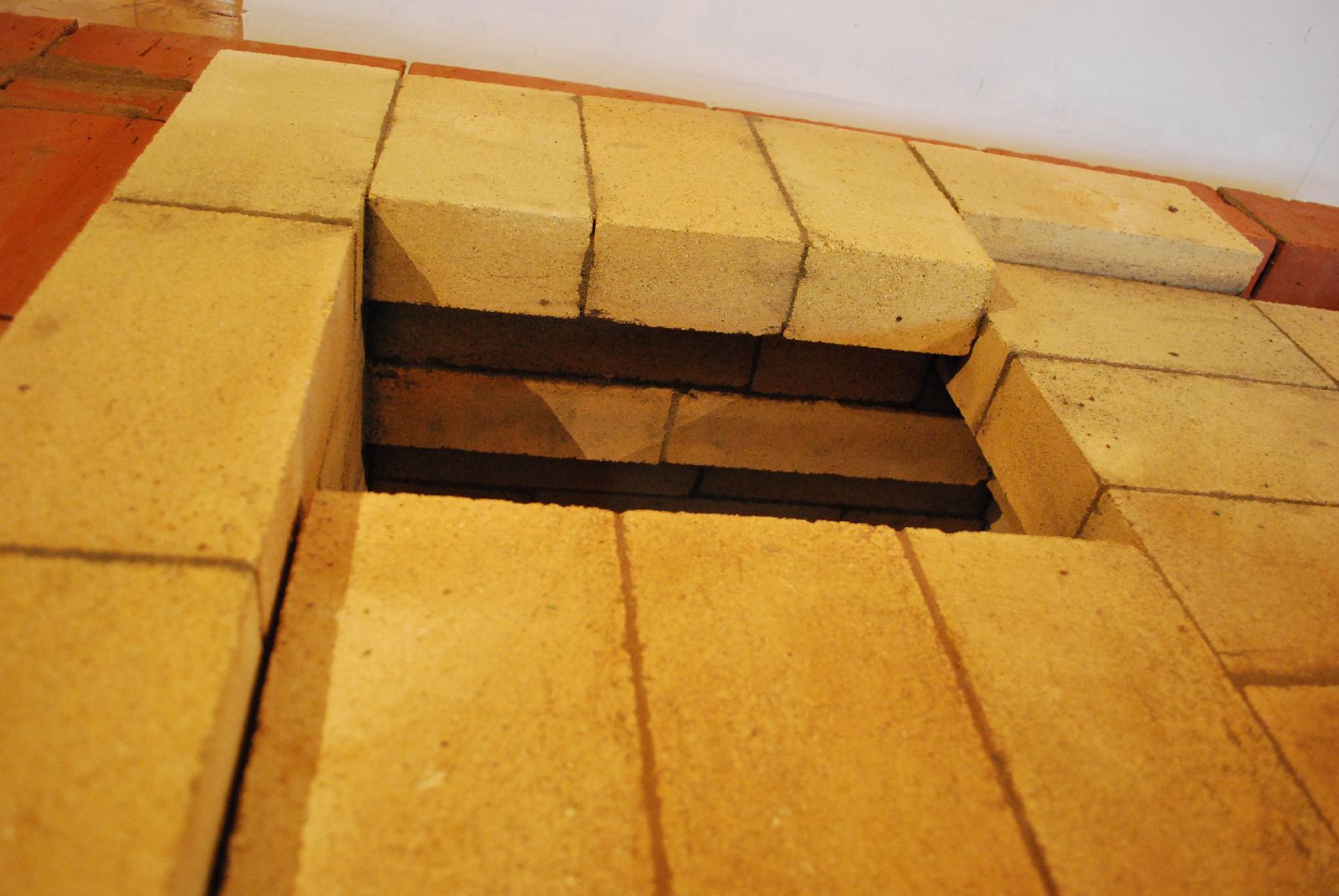
The throat from the fire box at top right, the down channels in to the lower chamber, on each side of the hearth, and the exit flue from the manifold to the chimney at bottom left.
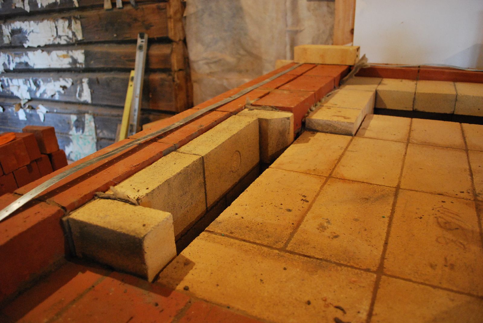
The liner of the lower chamber is laid up to 1cm lower than the row of facing brick on to which will be laid the header course that will support the vault.
The portion of exposed facing brick between the lining of the down channel and the fire box wall, at hearth level, is the only place in the stove that could not be double skinned. This has arisen only because the face on to which the fire box loading door is located is recessed by half a brick into the plain of the facing. It will be eventually shielded.
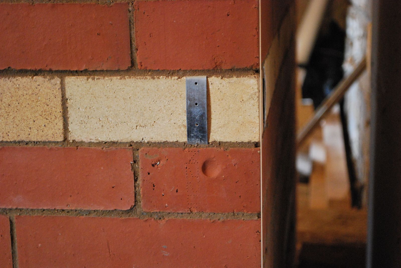
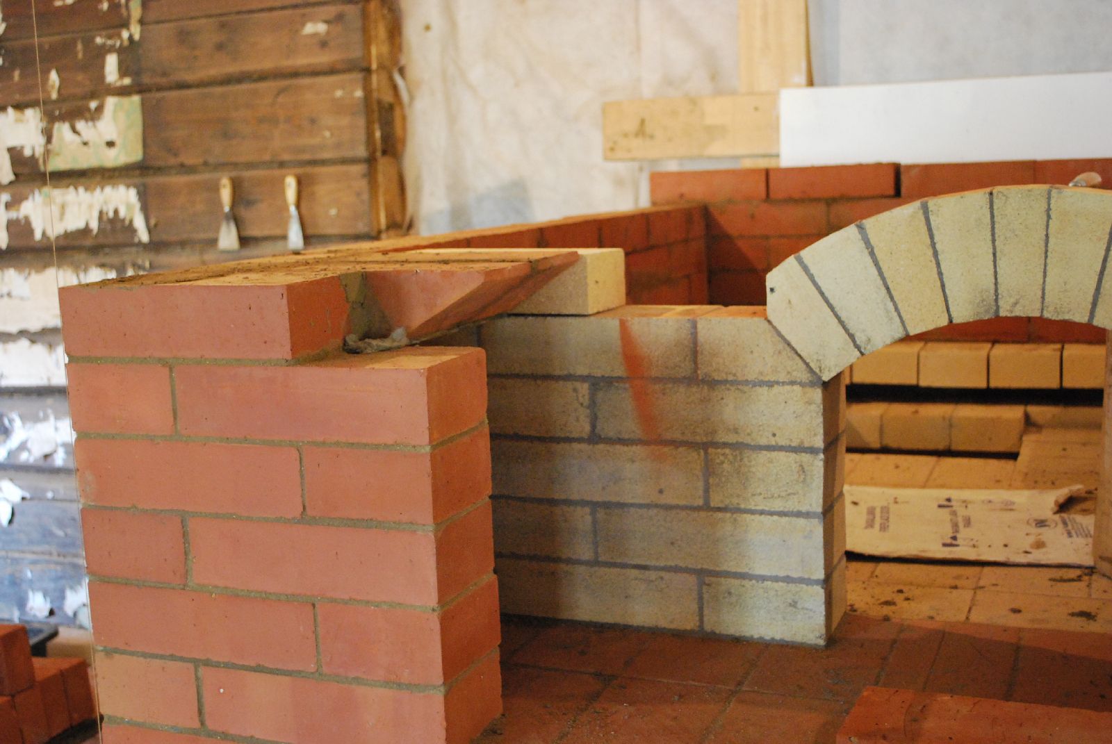
The course of refractory brick headers that will support the vault is strapped to together with galvanized steel strapping. The headers are laid onto the facing brick but do not actually contact the brick of the fire box or throat, or the liner wall of the down channels.
The joints are raked out from the portion of the header that protrudes into the bake chamber. This allows each brick to expand as it becomes extremely hot at one end, without opening the head joint in the facing.
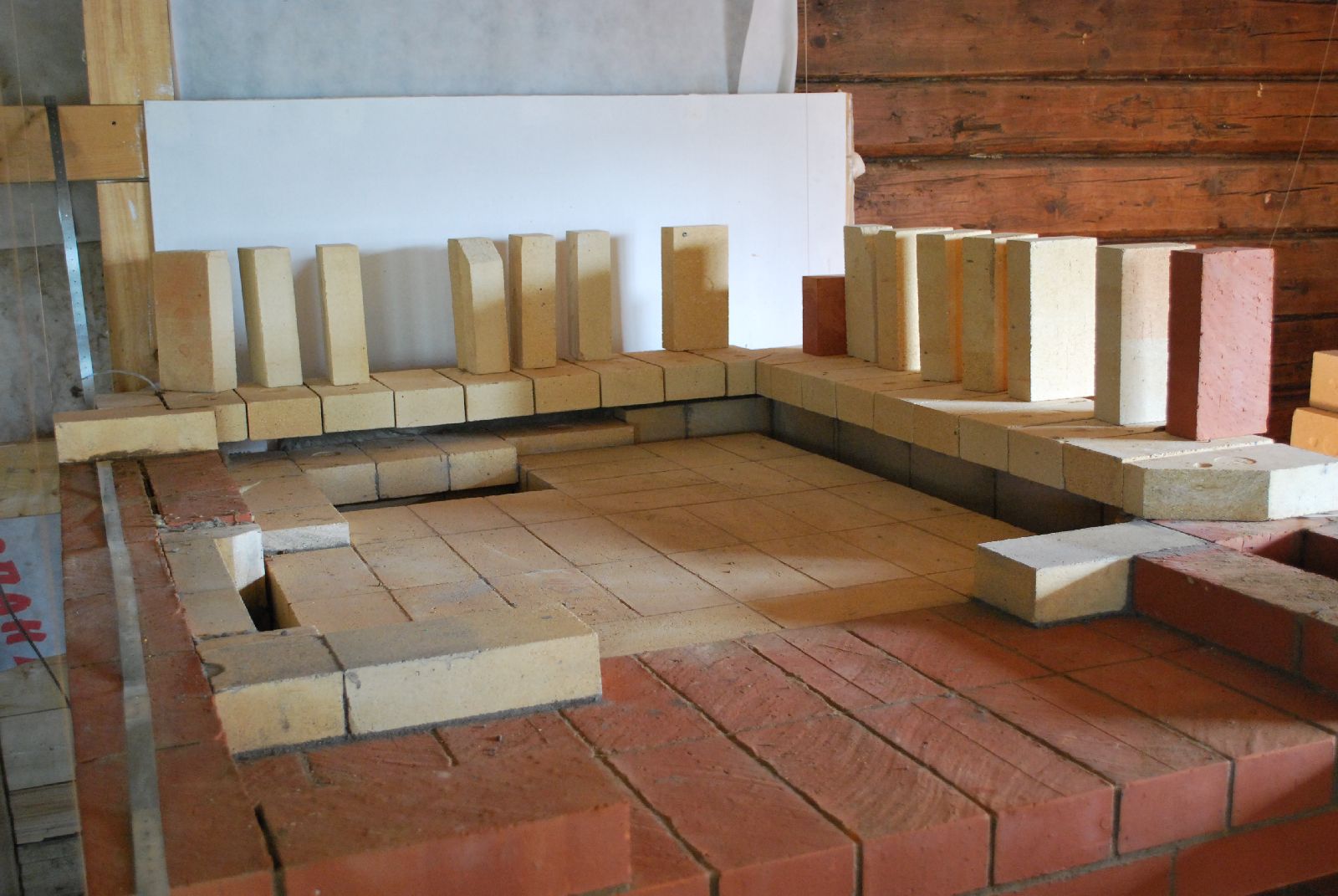
This course of refractory brick headers will support the vault and its rear wall. The front wall, in which is located the loading opening, rests directly upon the hearth.
The steel straps are screwed into the joint between two bricks.
Though hidden on the more visible corner above the fire box loading opening, the strapping is allowed to be seen on the opposite rear corner.
The first row of facing brick locks the headers in place. The first three courses of the avaloire and the loading opening in the front wall.
It is against the established rules of the trade to bond refractory brick with clay facing brick.
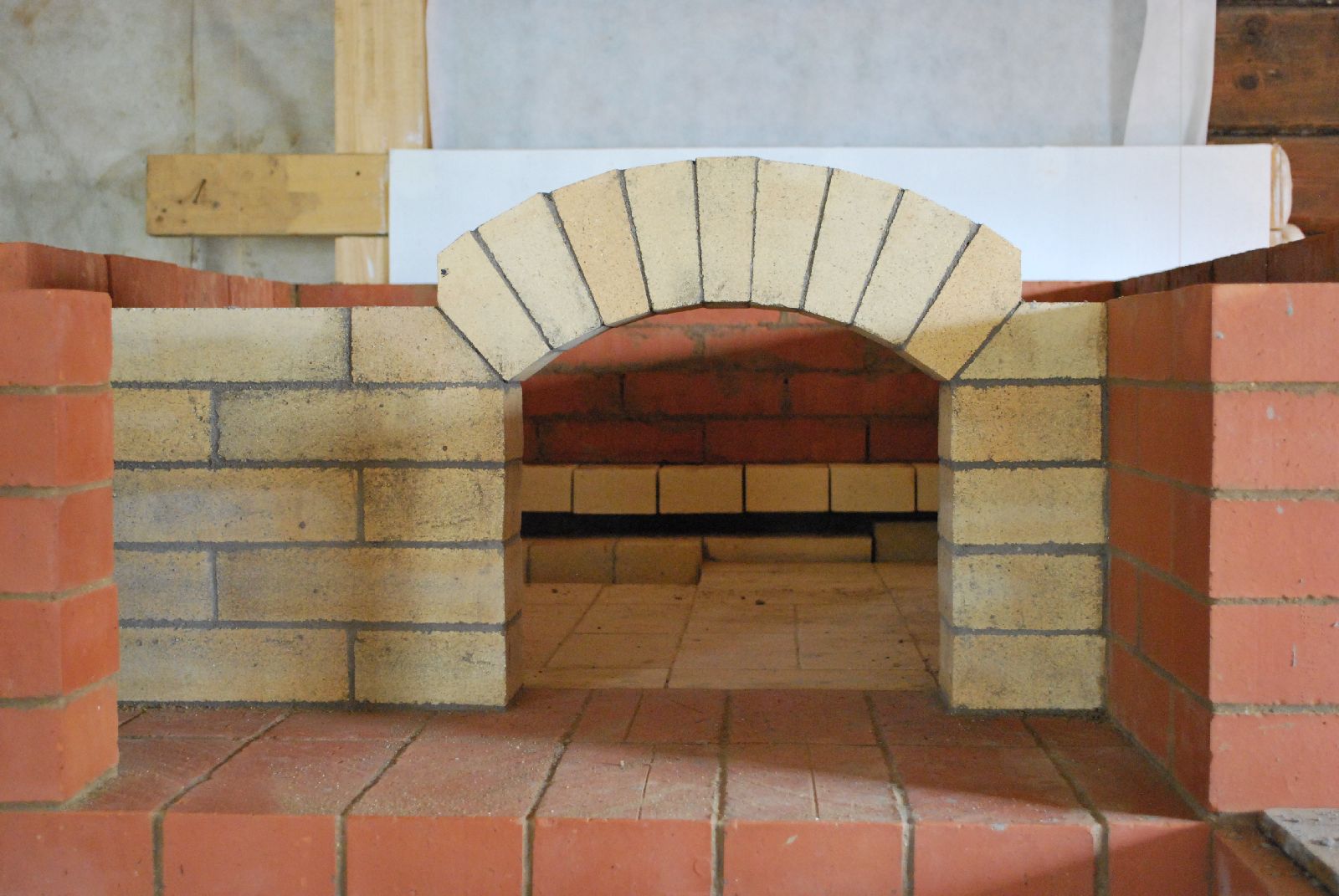
The arch over the loading opening in the front wall of the bake chamber.
The two skew cut brick form the course onto which will rest the course that forms the floor of the first niche in the adjacent wall. The brick are skew cut to allow the steel shield, used to close the loading opening, to be slid to the left allowing the opening and closing of the oven without having to lift the shield out of the avaloire.
The front wall and facing are laid up before starting the vault.
The rear wall of the bake chamber is free floating, having no contact with the facing behind or to the sides.
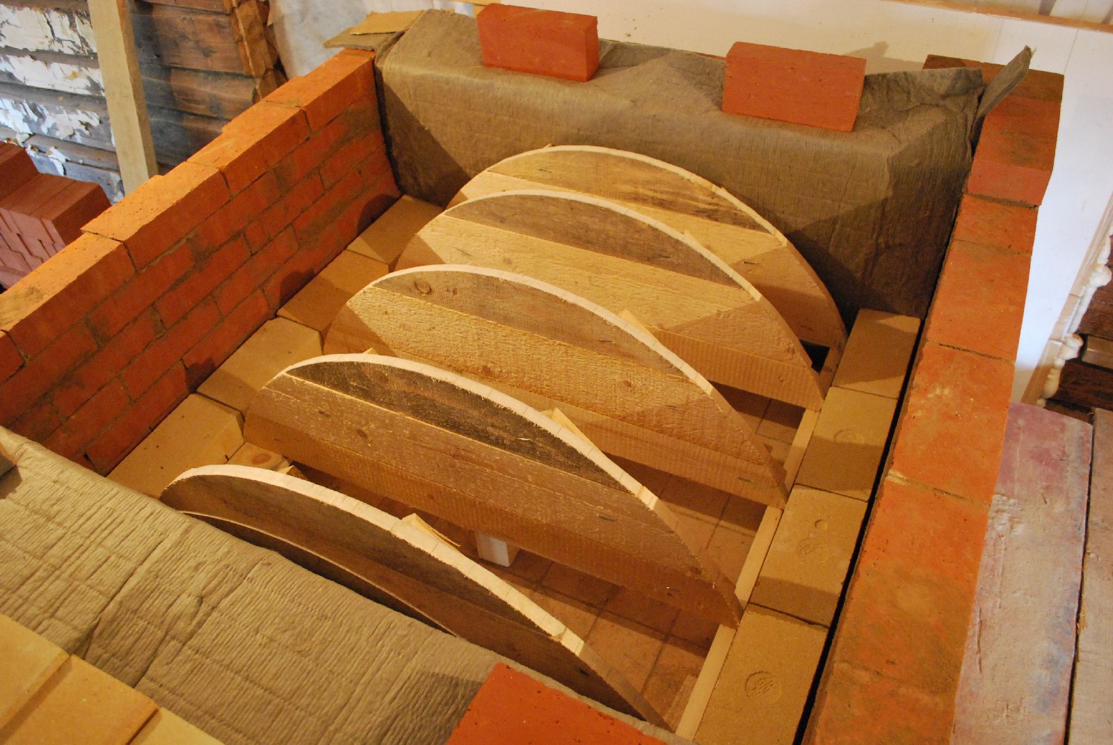
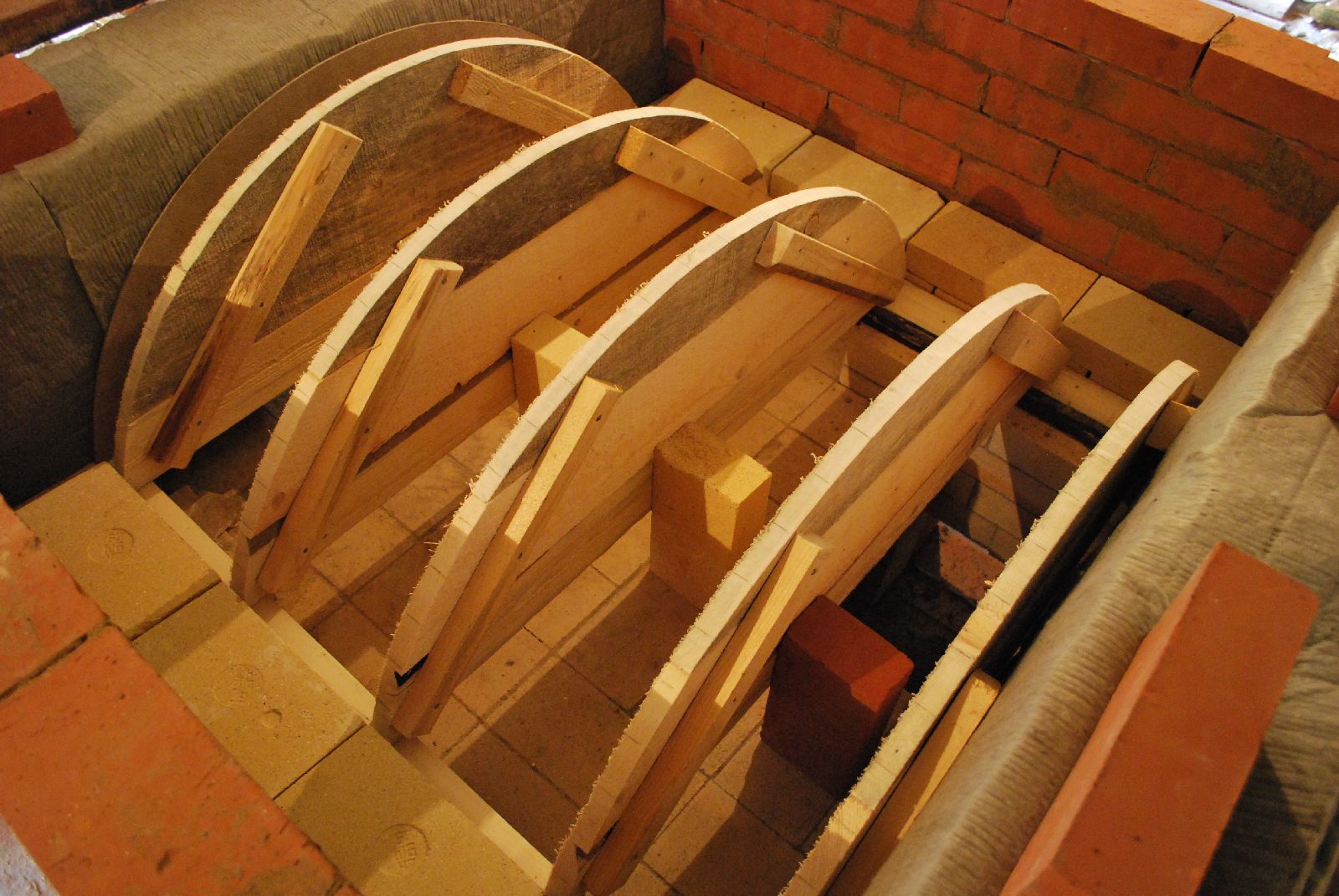
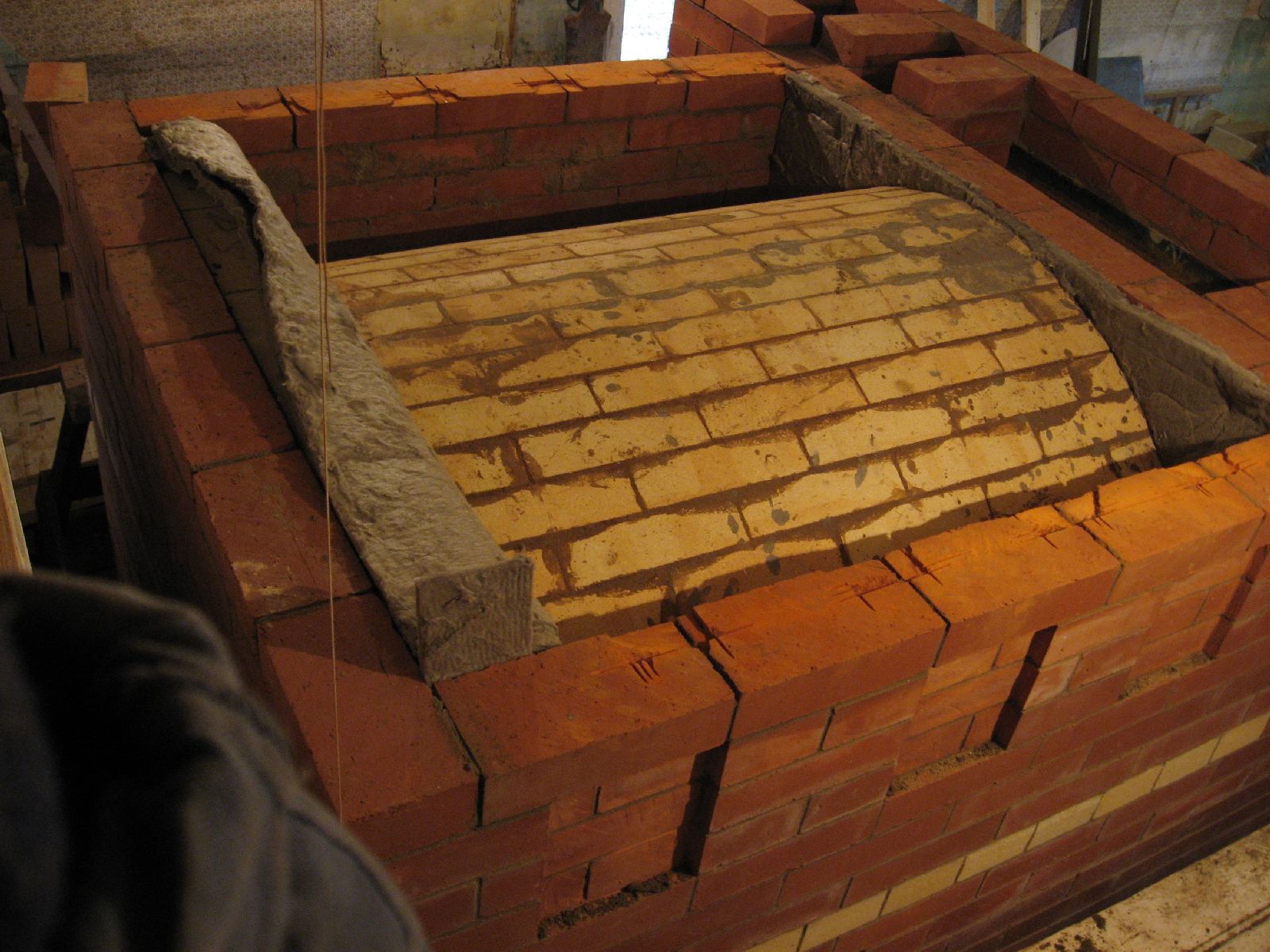
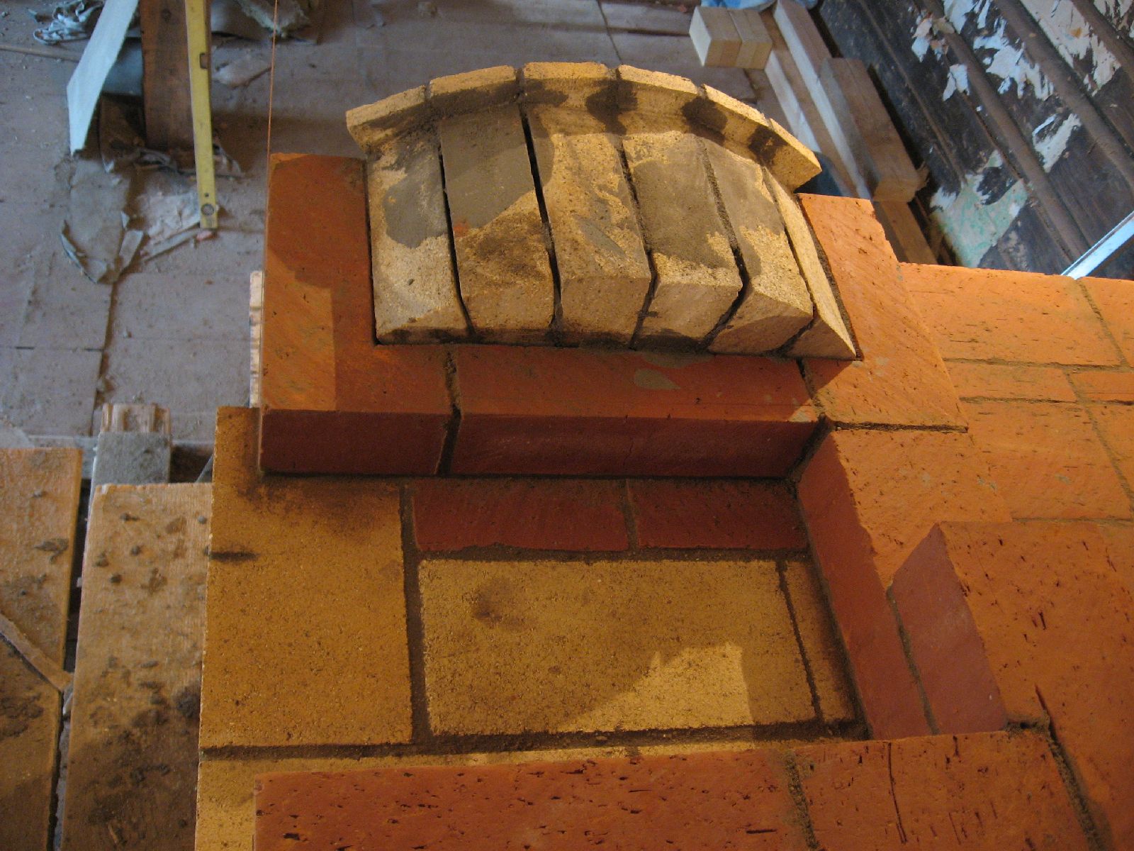
Staging and forms in preparation for the laying of the vault.
The vault forms are laid out in a manner that they will support each brick of the vault.
Note that the front and rear walls are gasketed.
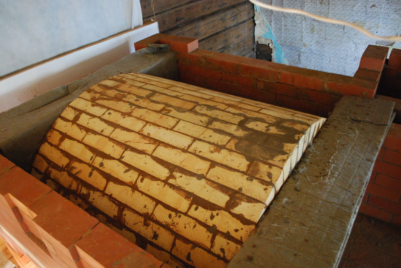
The vault is of arched refractory brick, called SHA-47 250/124/65-55, laid with clay mortar, in a running bond.
The completed vault. The last course was laid in refractory mortar, which permitted a slightly tighter joint, and avoided a tricky cut along the whole course.
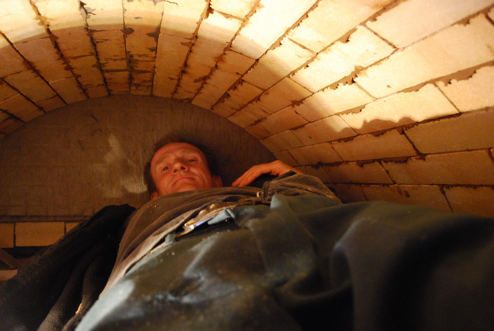
There is only one way to clean and fill the joints on the inner surface of the vault.
The facing is brought up to height. The front wall over the loading opening is now laid in clay brick. The last course of facing brick have been ground down to take the 'T' bars that will support the sleeping platform.
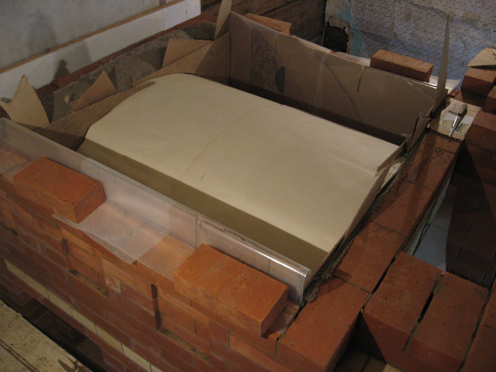
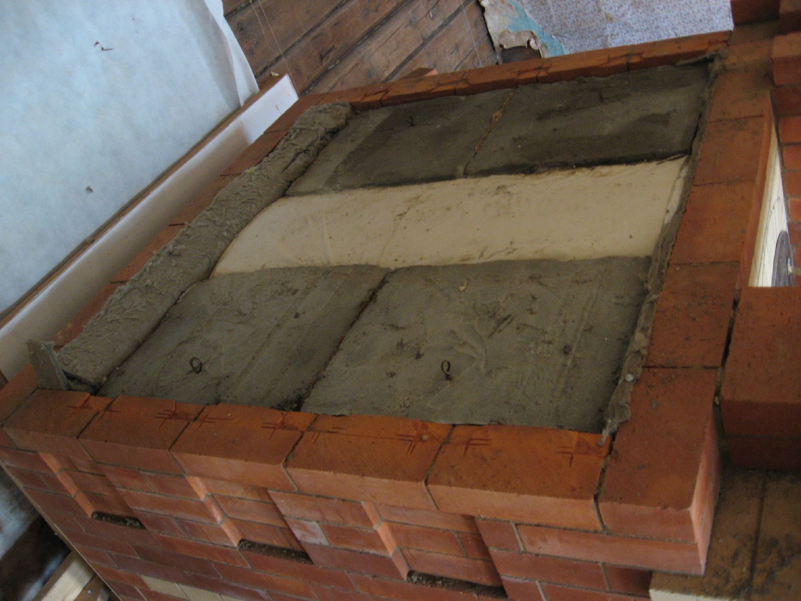
Before pouring concrete over the vault it is covered with 4 sheets of thin paper that act as a slip joint, and the facing gasketed with cardboard.
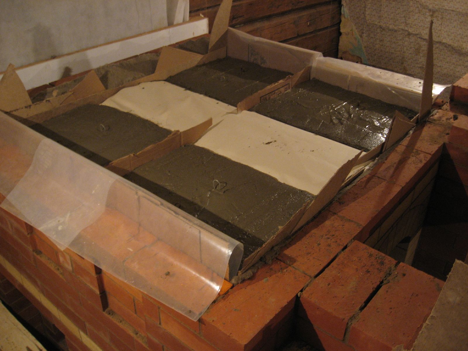
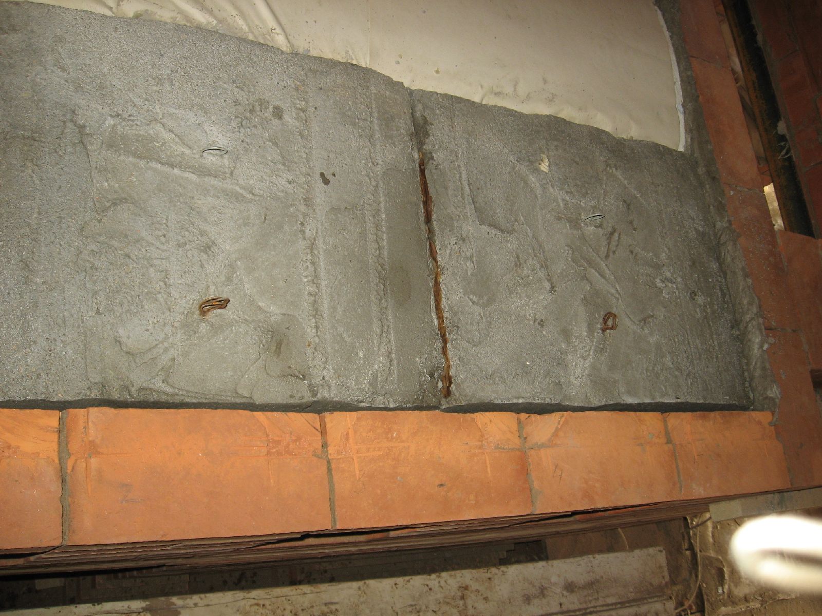
Concrete is poured to form 4 separate molds. Note the wire loops in the molds to aid their removal, if that should ever be necessary in the future.
The cardboard is removed.
The molds are free floating which allows them to expand against the vault and facing without forcing it to crack.
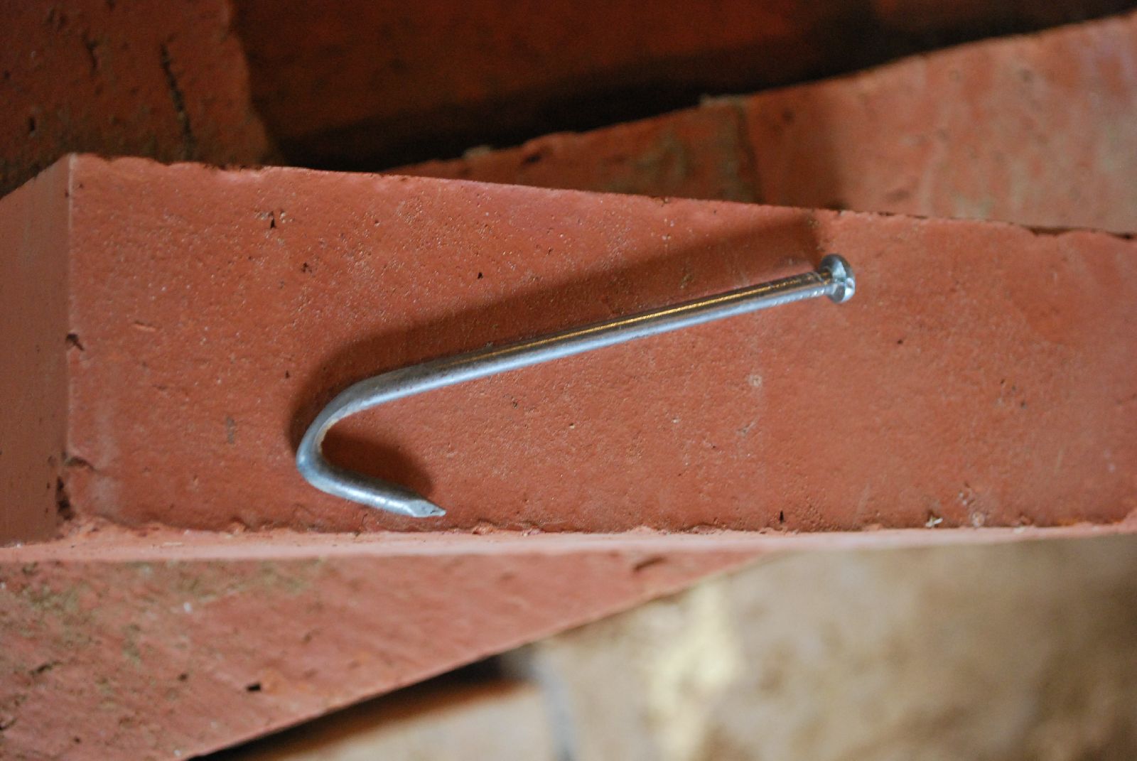
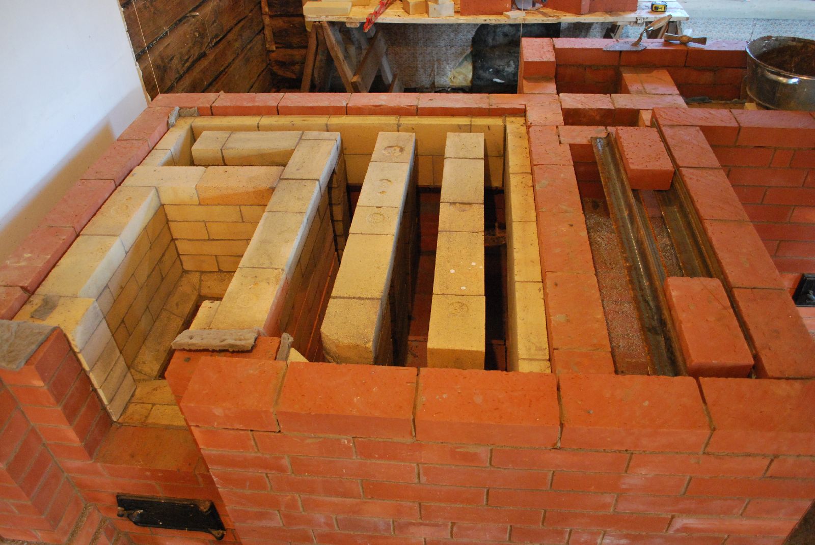
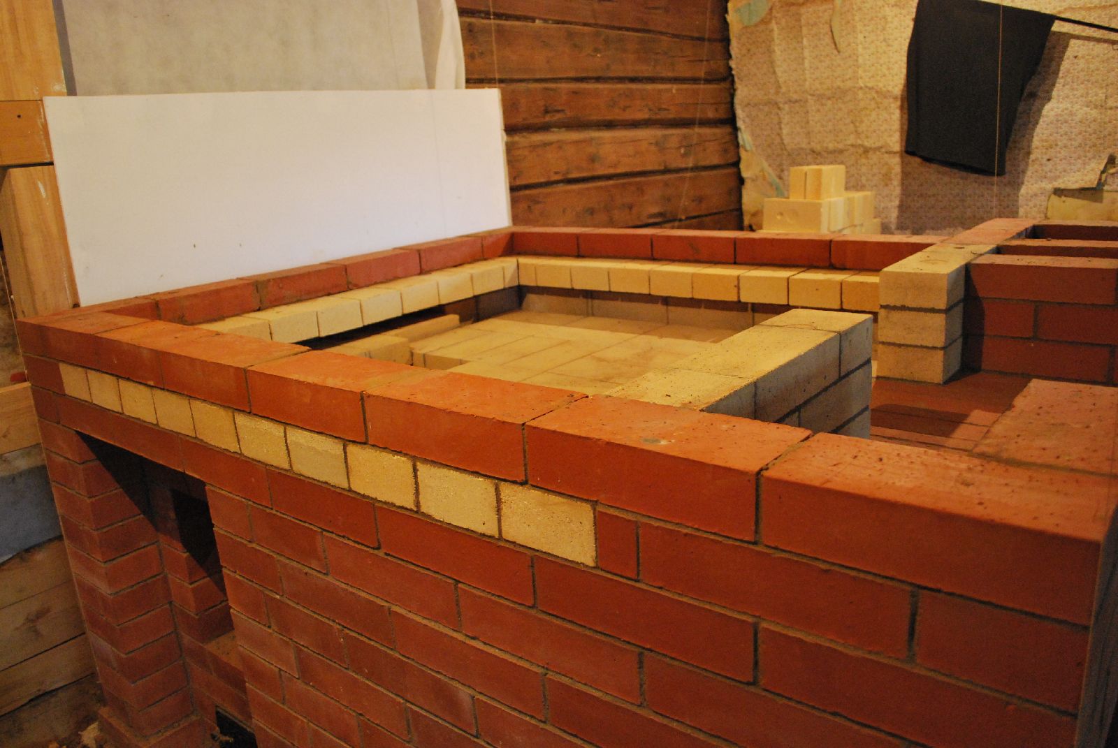
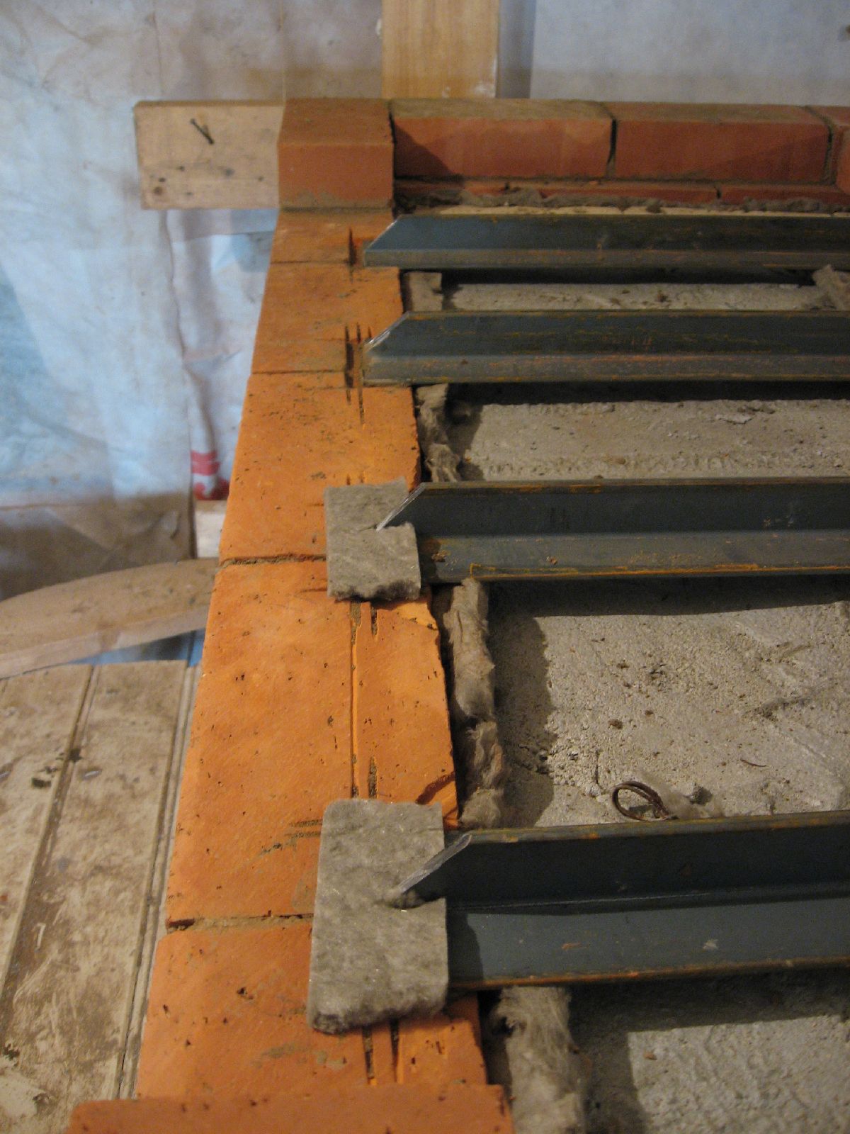
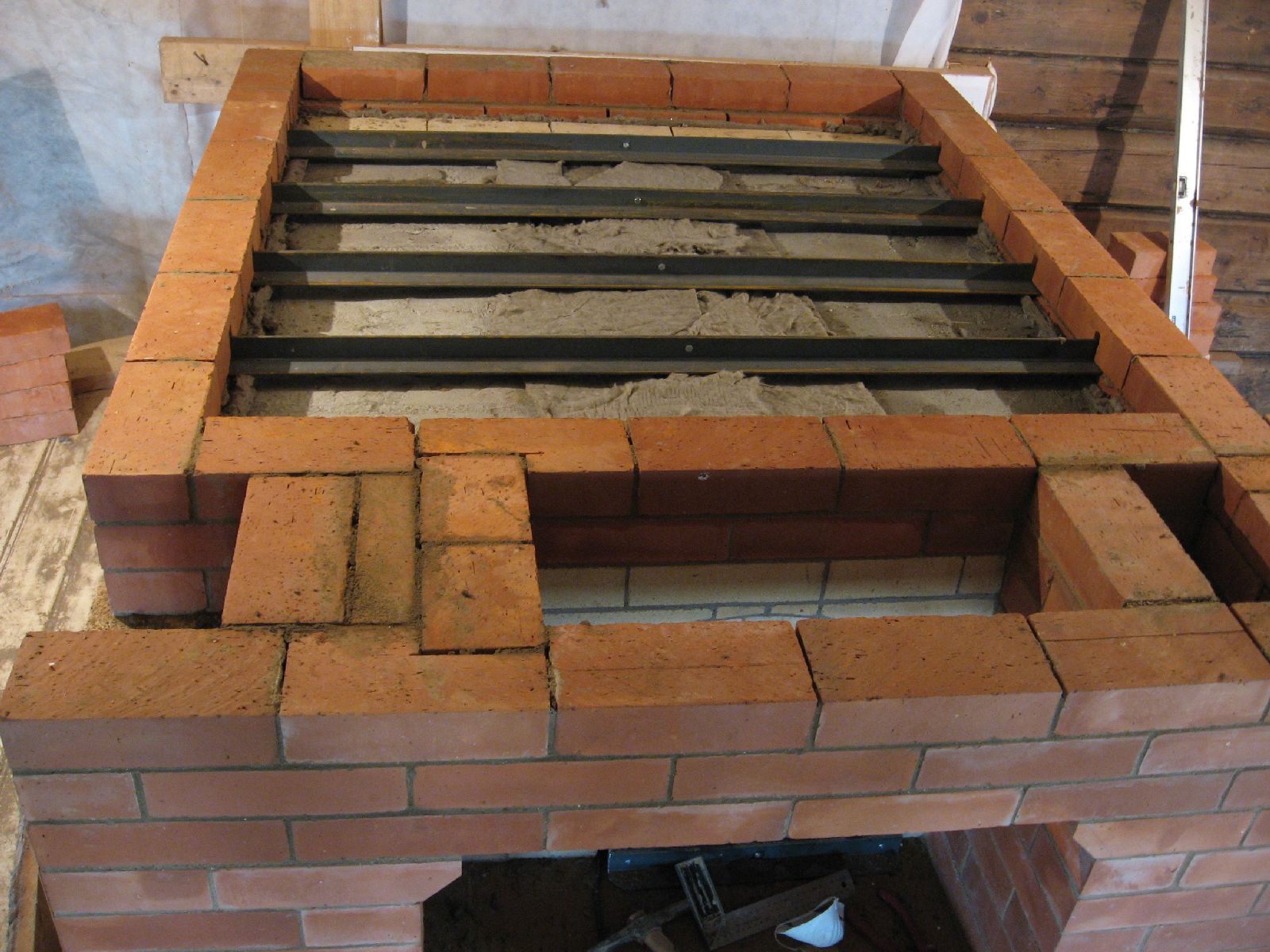
'T' bars are laid across the vault, resting upon the facing. These bars will support the two courses of facing brick that will close the stove and form the sleeping platform. The ends of the bars are gasketed with mineral wool.
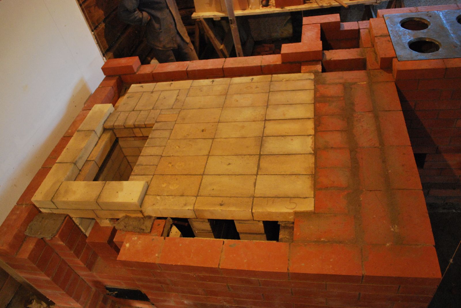
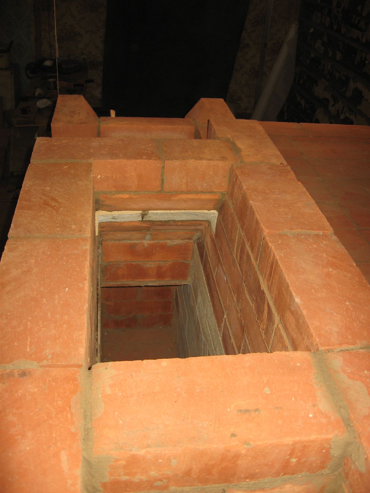
The 'T' bars are locked in place by one row of facing brick. At front left is the opening for the first of two niches, then the avaloire, centre, and at right the flue from the lower chamber i.e. the exit of the Teplushka's smoke path in to the chimney.
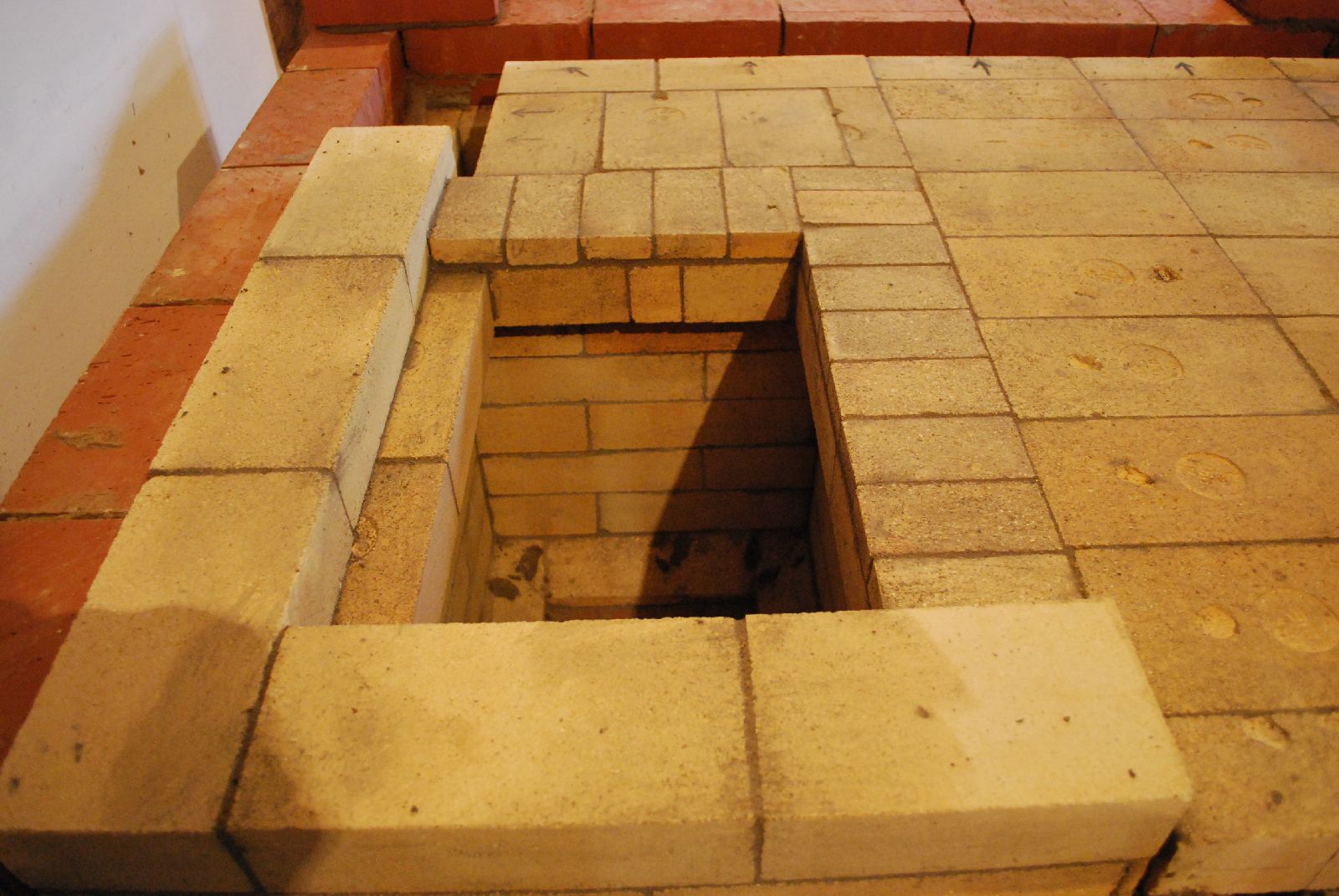
View across the top of the avaloire. The first course of facing brick are laid onto the 'T' bar supports (at right).
The second and final row is laid to finish the top of the oven. The refractory brick laid on this course will form the second niche and are laid here only for aesthetics.
The final course forming the sleeping platform is laid, the second niche started, and the avaloire reduced.
View down the avaloire, beneath the niches.
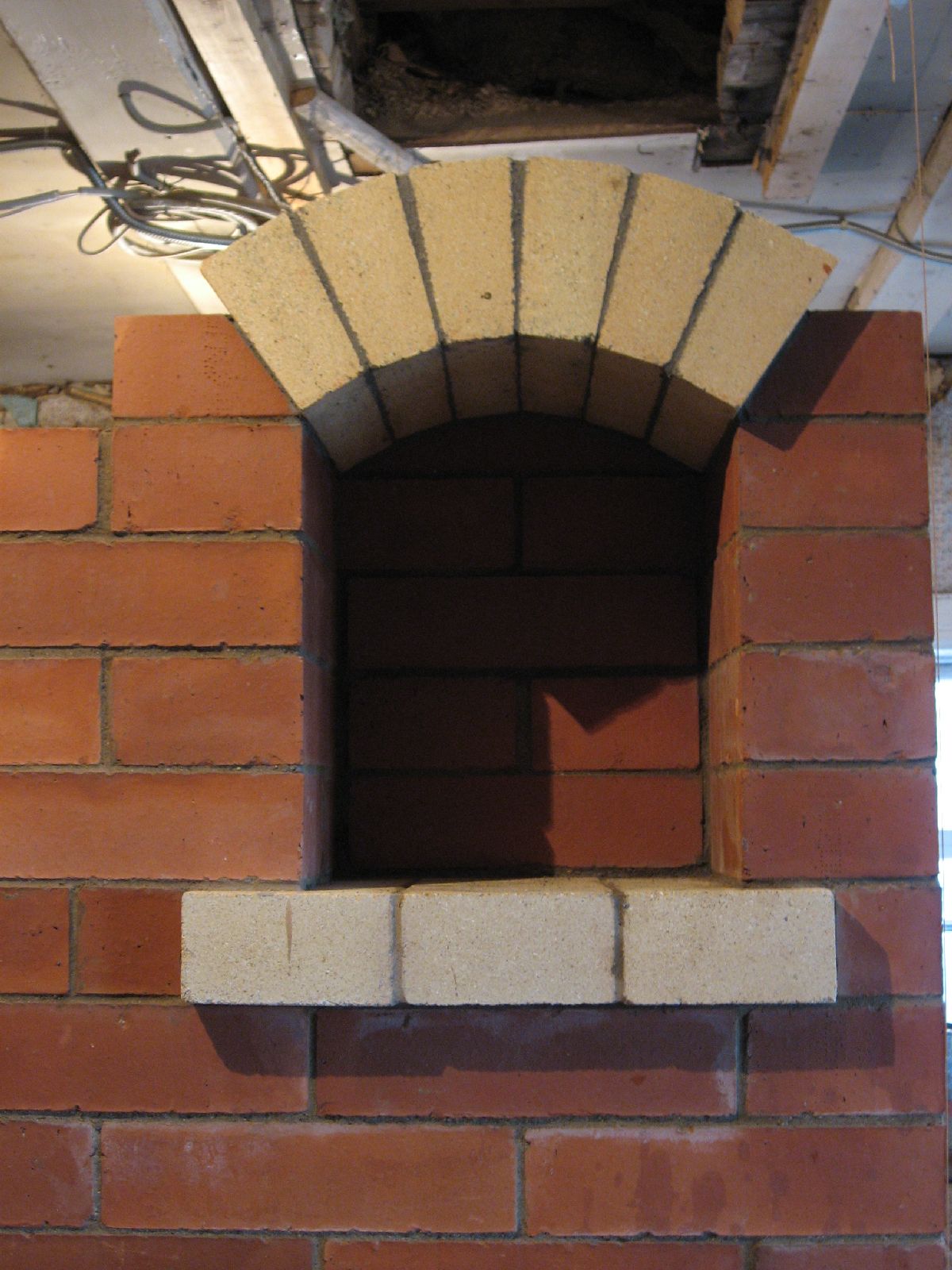
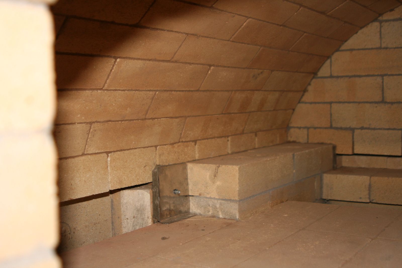
The lower niche. The arch is made from refractory arch brick called SHA 45 230/113/65-45.
The refractory brick arch over the lower niche. The voussoir of the arch protrude from the wall and are cut back on top, in the manner seen here, to accommodate the spandrels, and avoid the difficult curved cuts necessary on the spandrels, if the voussoir were laid flush with the face of the wall.
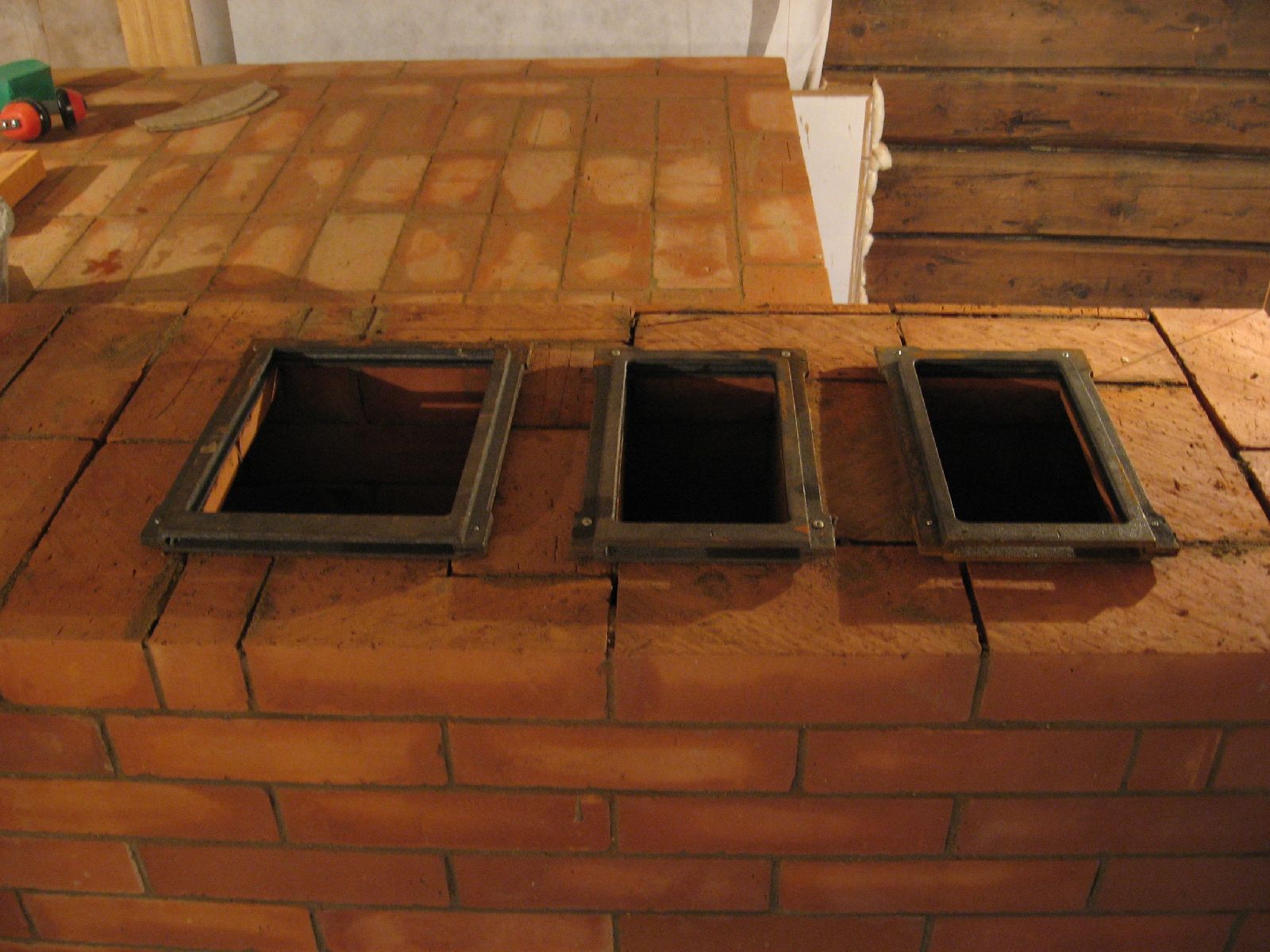
The three damper frames in position on top of the avaloire. The avaloire's damper is to the left, the Teplushka in the centre, and the cookstove at right.
The second niche before laying the arch.
The first course of brick above the three dampers.
The three flue openings flow in to a manifold on to which is built the actual chimney.
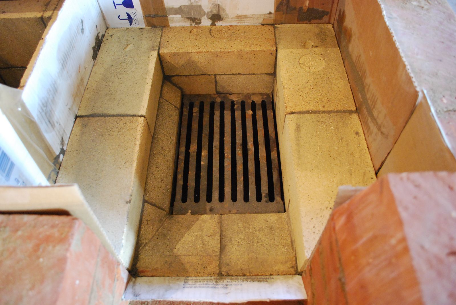
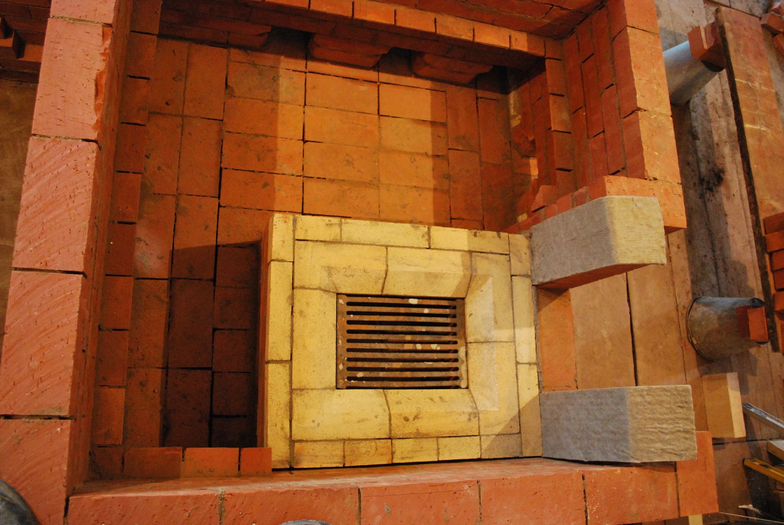
The cookstove's fire box.
The only portion of the Teplushka not double skinned is protected by a stainless steel heat shield that holds a piece of wool in place over the exposed surface.
The three square recesses in the facing to the left of the niche were made to take decorative ceramic tiles.