Air Requirements and Related Parameters for Masonry Heating Systems
Prepared for:
The Research Division
Housing Technology Incentives Program
Canada Mortgage and Housing Corporation
CMHC Project Manager: Don Fugler
Prepared by:
Norbert Senf
Masonry Stove Builders
March 3, 1994
Navigation Instructions: Scroll down to read document. This Table of Contents is interactive. You can click on a topic of interest to go there directly, and return to Table of Contents using your browser's "Back" button.
Masonry heaters are woodburning appliances that have the ability to store heat in a thermal mass. Typically, a 10 to 20 kg wood charge is burned rapidly with a liberal air supply, and a 1 to 2 hours burn will yield a continuous heat output for 12 to 24 hours. Because energy storage makes a low heat output possible without having to resort to smoldering burns (ie., low burn rates), it allows cordwood fuel to be burned with very low emissions of atmospheric pollutants. Although based on designs that are hundreds of years old, the operating characteristics of masonry heaters make them particularly suitable for modern, energy-efficient housing. However, it is not clear how much air they will draw from the house during operation.
This research was designed to answer that question. Various aerodynamic parameters were measured on five different masonry heaters, with the aid of a specialized piece of testing apparatus, the CMHC duct test rig. Air consumption data was obtained under a variety of operating conditions. Air leakage was investigated in two heater systems, as were the tailout (diedown) characteristics. Finally, the air leakage on four types of masonry heater firebox doors was tested.
Masonry heaters with overfire combustion air systems appear capable of operating with maximum air consumption rates of 30 L/s or under. The underfire air units tested required considerably more air. In a typical R-2000 house, drawing 30 L/s of inside air would result in only about 3 Pascals (Pa) of depressurization, well within any house depressurization limits.
If the heaters were fitted with a separate outside air supply, the only air requirement from the house would be the air leakage through the doors. Testing on a number of doors showed that the leakiest door would draw only 6 L/s at 25 Pa, an amount that would not cause any noticeable degree of house depressurization.
One problem with some wood heating devices is that the chimney flow may reverse when the fire dies down, causing smoke and/or carbon monoxide spillage into the room. Testing showed that this is not an issue with masonry heaters, as the basic design stores large amounts of heat that maintain chimney draft even after the fire subsides.
The data supports the view that the majority of masonry heater types can be expected to function properly in airtight houses, with or without outside combustion air supplies.
DISCLAIMER
This project was funded by the Canada Mortgage and Housing Corporation. The views expressed are the personal views of the author. The Corporation does not accept responsibility for them.
Masonry heaters are heat-storing appliances. They have been in use for many years in the colder regions of Europe. Prior to 1981 they were almost completely unknown on this continent, but have been making steady inroads since. Recent North American testing indicates that as a class they are capable of operating at the very low average particulate emissions (PM) levels necessary before biomass fuels can become a viable household-level energy option. This could be of significance to recent trends in “green” architecture, since biomass is potentially a zero net carbon impact (renewable) fuel. Masonry heaters are particularly well matched to operation at sustained low output levels (.5 - 3.0 kW) typical of the average heating load in new energy efficient housing. The present report investigates several aerodynamic characteristics of these appliances that may affect their performance in low energy housing that is airtight. The author conducted tests with the CMHC Duct Test Rig (DTR), a specialized tool that is capable of measuring a wide range of airflows and pressure versus flow (impedance) characteristics. Specifically, the air consumption of masonry heaters was measured in two combustion air configurations (overfire and underfire). Secondly, tailout was investigated. This is the resistance of a solid fuel appliance to pressure induced combustion gas spillage at the end of the burn cycle, when carbon monoxide production typically is high. The third item investigated was the airtightness of several standard masonry heater firebox doors. It also became apparent during the testing that air leakage in the masonry heating system as a whole needed to be addressed. Finally, some leakage and calibration considerations of the DTR itself were investigated.
Masonry heaters are characterized by a large masonry thermal mass that is used for heat storage. A charge of cordwood fuel of up to 25kg. is loaded into the firebox, ignited and then rapidly burned. Much of the resulting heat energy is transferred into the masonry mass through direct radiation in the firebox and through flue gas heat exchange channels, and is then slowly released into the heated space over a number of hours after the fire is out. A typical one to two hour burn will result in a 12 to 24 hour heat release, depending on the heater type.
All of the heaters investigated in this report are of the contraflow type. Originating in Finland, these are regarded as being the most fireplace-like of the masonry heaters, and are the most common type built in North America. They are characterized by a raised firebox and a set of downdrafting heat-exchange channels that terminate in a chimney exit at floor level. A secondary characteristic of all the heaters tested is that there is no combustion air control except for on/off in three of the heaters. All of the heaters incorporate a sliding damper in the chimney which provides the only control. Its main purpose is to interrupt chimney flow once the fire is out, since the burn itself is essentially unregulated except for the throttling at the combustion air inlet orifice.
Five heaters were investigated. One (RUP) was handbuilt by the author in 1981, and is one of the earliest modern contraflow heater built in Canada. The second heater (TEM) is a current production model manufactured in Canada by Tempcast Industries, and consists of precast refractory modules that are site-assembled into a heater “core”. The heater core then receives a site-installed masonry facing, typically 100 to 150 mm in thickness. It was tested at the Tempcast factory as a core with no facing. The other three heaters are examples of a second Canadian system, Heat-Kit. It is a hybrid system in that the core uses precast factory components that are combined at the site with standard refractory modular units (firebricks). This system was developed by the author’s company in 1985. One unit (MSB) was a prototype core that was tested with no facing. The second one (SEN) was a core with a prototype facing, and the third (AND) was a core with a typical clay brick facing. Typical operating parameters for the heaters studied are:
Firebox size: .09 to .12 m3
Fuel load: 15 to 25 kg (wet basis @ 20% moisture)
Firing cycle 24 hours (typical) or 12 hours (high output)
Average output: 2-3 kW (typical) or 4-6 kW (high output)
Storage Capacity:............50 kW-h (typical)
With the advent of more efficient housing standards, the use of direct-connect outside combustion air supplies for vented appliances has become an issue. CMHC funded a study of fireplace air requirements in 1989which concluded the following:
• Fresh air intakes proved to be of variable utility, supplying close to all required air in some fireplaces and less than 25% in others. Those directly connected to the firebox could match air requirements but could be dangerous in reverse flow incidents, when combustion products flow out through the intended intake.
• Air intakes which are connected directly to fireboxes can experience reverse flow of hot gases through the duct. Therefore these ducts should be isolated from combustible materials. Direct-connected air intakes are not recommended unless the firechamber is relatively tight and isolated from the house when the doors are closed.
• Backflow prevention dampers may provide a solution to the reverse flow problem
• All fireplaces tested would spill, during fire diedown (tailout), if a room depressurization of roughly 10 Pascals was maintained.
A few masonry heater models are ULC listed and are thus installed in accordance with the terms of their listing. Most masonry heaters however, even factory kits, are typically site-assembled and are usually accepted under the masonry fireplace and chimney provisions of the applicable building code. The National Building Code of Canada has for several years had a requirement for a 100 mm outside air duct vented directly into the firebox of masonry fireplaces. The above-mentioned study, and others, have pointed to possible deficiencies in this arrangement. Recently, there have been several well-documented cases of complete draft reversals in factory-built fireplaces where the air supply has become a chimney and the chimney has become the combustion air supply. This is quite plausible, and even expected, theoretically. When there is wind loading on a house, the windward side sees a positive pressure while the three leeward sides see varying degrees of negative pressure. In other words, the supply hood for the fireplace combustion air has a less than even chance of seeing zero or positive pressure during wind loading. Up to 50 Pa negative wind pressure is not unheard of, enough pressure to overcome the chimney draft. No building code presently addresses this issue.
At least one housing standard, the voluntary R-2000 performance standard, has addressed outside combustion air. It was argued that EPA (United States Environmental Protection Agency) -certified appliances due to the nature of their construction, were unlikely to consume air at a high enough rate to cause an airtight house to exceed the commonly accepted HDL (House Depressurization Limit) of -5 Pa. It was reasoned that, by requiring all solid fuel devices to be EPA certified, outside combustion air could be eliminated. This approach creates certain difficulties for masonry heaters. First, EPA certification is clearly only a surrogate standard, since it regulates PM (particulate emissions) and efficiency, but not air consumption. Presumably air consumption rates can be inferred. Unfortunately, masonry heater are classed as “non-affected facilities” by EPA and therefore uncertifiable under EPA rules. Recent experience in the solid fuel industry indicates that once standards in new areas of regulation are adopted, they have a tendency to propagate and become a defacto status quo. The EPA rule is an example of this. There is therefore some urgency attached in the masonry heating sector, still in its infancy in Canada, to establishing a performance database that can serve as a basis for establishing sound future standards.
Negative house pressure can contribute to spillage at startup and at diedown. It can be induced by exhaust appliances, by wind loading and by stack effect. An HDL of -5 Pa is commonly used. Negative house pressure relates to masonry heaters in two ways. The primary concern has been the issue of air consumption by the heater, ie., the heater causing negative pressure in the house. A secondary issue is the effect of house negative pressure on the heater, ie., will spillage occur and under what conditions?
A popular concept with airtight housing has been the idea of aerodynamically decoupling the appliance from the house. Airtight doors, so the theory goes, will prevent a fireplace from spilling into a depressurized house at startup or diedown. The 1989 Sheltair tests found little relation between door tightness and spillage susceptibility. Similarly, theoretical work with WOODSIM found flaws in this concept. Negative house pressure is, by definition, negative relative to ambient outside pressure. Since the effect of an outside air supply is to bring the firebox to outside pressure, it cannot be demonstrated to prevent spillage. Similarly, a door that leaks 5 L/s at 10 Pa is considered to be quite tight for a fireplace door. Five litres per second of acrid woodsmoke is not a negligible amount. Notwithstanding these considerations, the airtight door concept remains a popular one. “How tight is tight?” becomes the next question. In order to investigate this, a special door test enclosure for the DTR was constructed, and a number of pressure vs. flow tests were carried out on a selection of doors in general use in masonry heaters.
Tailout is the term used to describe phenomena at the die-down stage of a solid fuel burn. As the wood charge is consumed, chemical energy conversion slows in the charcoal phase. Less heat is available to energize the chimney, and other factors such as dilution air can contribute to chimney cooling. The thermal flywheel effect of stored heat in a high mass (masonry) chimney can help maintain draft. So can elements such as firebrick linings in fireplaces and stoves. Low mass chimneys, and chimneys of any type that are outside the building envelope, cool faster. Certain combinations of circumstances can become dangerous. The greatest potential danger is a draft reversal, i.e., combustion gas spillage, during the charcoal phase of the burn: carbon monoxide levels are high at this stage, and there is no smoke to alert the occupants, as there is during startup. CMHC has previously conducted a major series of studies under the title “Residential Combustion Venting Failure - A Systems Approach” and identified interactions among different parameters in the house/appliance system.
One of the current issues in masonry heater design is the question of overfire versus underfire combustion air. This refers to whether or not air is introduced to the fuel charge from below, through a grate in the firebox floor. Emissions testing conducted by the author and otherson masonry heaters recently indicates a 100-400% increase in particulate matter (PM) emissions with some common underfire air systems. Also, excess air levels are significantly higher. Excess air refers to the amount of combustion air over and above the theoretical amount (stochiometric) required to complete the oxidation reactions when wood burns. Air consumption by the heater is a function of two parameters, burn rate and excess air. Since underfire air increases the burn rate as well, it was expected to be one of the main variables influencing masonry heater air consumption rates.
Several spreadsheet forms were designed in Excel for Windows. The main form is for the air consumption tests. Background information and test data is entered. Air flow data from the DTR is read as a flow pressure across one of six orifices which are selected by detents on the DTR. The detent letter and flow pressure are entered in the appropriate columns, and the spreadsheet then uses a lookup table to calculate the flow in L/s. As the data is entered, the spreadsheet automatically constructs a graph of flow vs. time. The completed data form and the graph are then printed out as two separate pages. Several test runs use an expanded version of this template to record and display up to three channels of temperature data as well,
A modified version of the template is used to record pressure versus flow and damper opening versus flow data and display the data on a log-log graph.
It was felt prudent to establish some kind of calibration for the DTR that could serve as a reference at a later date if required. Accordingly, flow vs. pressure curves were taken with a set of square orifices cut from a sheet of heavy mylar. If the same orifices are used for a future retest, they will relate the state of calibration of the DTR for this test series relative to any future recalibration of the DTR.
On all of the heaters, the air flow at the combustion air intake was measured. Only one heater (RUP) had an air inlet in the firebox door itself. Since it was not a glass door, it was fairly easy to construct a hood to cover the entire door without overheating the hood. The other heaters all had ceramic glass doors, and also had air inlets that were separate from the doors. An average burn has an energy conversion rate in the 20 - 40 kW range, and therefore heat release through the ceramic glass is considerable. Since separate door leakage tests were conducted, it wasn’t deemed necessary to construct special heatproof hoods for the glass doors. Instead, air flow was measured at the combustion air inlet. This is equivalent to measuring air flow at a direct-connect outside air inlet, if installed.
In order to investigate the effects of underfire air on air consumption rate of masonry heaters, an underfire air heater (AND) was retrofitted with overfire air and then retested. In addition, two heaters (SEN, MSB) that had already been retrofitted from underfire to overfire, were retested with the retrofits removed
Several tests were conducted to examine tailout on masonry heaters. Three heaters (SEN, AND, RUP) were fired on normal cycles. Standby or residual airflow was measured prior to each test run. On several runs stack temperatures were measured before, during and after the burn for various intervals, including long term decay.
An unanticipated consideration was that of overall system leakage. After discussion of preliminary test results with Skip Hayden (CCRL), the low measured air consumption rates were called into question on theoretical grounds. Although no flue gas analyses were undertaken in connection with the present study, existing data from CCRL and a number of other sourceson the Tempcast and Heat-Kit systems provided estimates of expected excess air levels. On one system in particular (SEN) air consumption was significantly lower than expected. A metal hood was constructed to measure both door leakage and door mounting leakage and to allow a tight connection to be established with the DTR in order to conduct a flow vs. pressure test of the whole system. System leakage was much higher than expected. Since the facing on this heater was not typical, a more typical heater (AND) with a standard brick facing was retested for flow vs. pressure.
A door test enclosure was constructed to allow the mounting of various doors for flow vs. pressure tests. First, a flow vs. pressure test for the door enclosure was conducted. Then, three commercial masonry heater doors from Finland and one from Canada were tested. A typical clean out door was also tested.
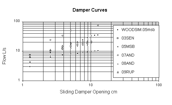
All of the heating systems incorporated sliding plate (guillotine) chimney dampers. Standby damper leakage, cold and hot, were measured. In addition, curves of flow vs. damper opening were generated for 4 dampers and for a WOODSIM damper simulation.
General. The data file name precedes the description of the tests.
Fuel for the first six tests (01TEM, 02SEN, 03SEN, 04SEN, 05MSB, 06MSB) came from the same stack of firewood, which was split maple and beech that had been in a woodshed for about 16 months. A sample piece was dried in an oven and found to have a wet basis moisture content of 17%. The remaining tests used the owner’s firewood.
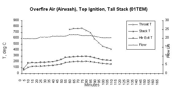
This was a current production Tempcast contraflow heater core. It was tested at the factory in Port Colborne, Ont. The DTR malfunctioned during the first test, resulting in a lengthy delay for repairs and a subsequent retest several months later.
The core was tested without a facing. Joints in the refractory modules had been sealed previously with silicone. The combustion air connection was in the bottom face of the door frame. The door frame consisted of 50 mm x 100 mm hollow steel tubing which is used to preheat the combustion air and convey it to the top of the frame. From there it exits downwards through four 12 mm x 180 mm slots which also function as an airwash for the door. The door was a new model single door with glass. It was gasketed and appeared to be airtight. The glass frame was cast iron. A masonry duct was constructed to make a connection between the somewhat inaccessible air inlet and the DTR. Firebox dimensions were 460 mm x 460 mm x 460 mm. Flue gases exited the heater to the rear at the base, went into a short masonry chimney stub and then transitioned into 200 mm dia. A-vent (stainless steel chimney with 25 mm of insulation). A sliding damper was incorporated into the stub chimney at floor level. The total stack height was the highest of all the heaters tested at 12.2 m. The system was equipped with thermocouples in the stack at floor level and at a height of 5 m, and at the firebox throat. Temperature data was therefore recorded as part of the test.
The heater had been fired with a small (approx. 6 kg) charge of wood about 4 hours previously. This is evidenced in the beginning stack temperatures of 86 C (floor level) and 64 C (5 m height). A Tempcast employee stacked the fuel in the firebox and ignited the charge from the top. The top ignition accounts for a slower start as evidenced in temperature peaks at 70 minutes relative to peaks with a similar fuel charge at 40 minutes in test 05MSB (overfire) and 35 minutes in test 06MSB (underfire).
This is a contraflow heater with a Heat-Kit core. Outside temperature was -17 C, so one would expect maximum chimney buoyancy and flows. Combustion air on this heater enters from the firebox floor immediately adjacent to the doors, ie., at the bottom and to the front of the wood charge. Combustion air consumption peaked at 11.2 L/s. A conservative instantaneous burn rate at the peak would be the 7.4 kg/hr (dry basis), based on burning 17.7 kg of wood with a 17% moisture content evenly over 2 hours. The stochiometric air requirement for this is approximately 10.5 L/s. Since excess air of at least 200% would be expected, the measured combustion air flow is clearly low.
The doors on this heater had undergone several years of “torture testing” and were considered to be fairly leaky. Subsequently, a hood was constructed to cover the door and the heater was retested (10SEN-re) and a leakage investigation carried out (LK-SEN).
This was a repeat of the above test with the heater “un-retrofitted” to underfire air. This simply consisted of removing the cover on the grate in the firebox floor. Interestingly, with a -25 C outside temperature and with the grate uncovered, we see a standby flow before the burn of 14.8 L/s, or 3.6 L/s higher than the flow during the burn in 02SEN. The airflow through the intake during the burn is doubled from the overfire configuration, at 22.6 L/s. At 45 minutes we see a temporary 2.6 L/s drop as the fuel charge collapses and covers part of the grate.
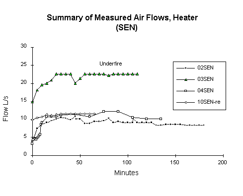
Even though leakage considerations are unresolved at this stage in the testing, we can still gain information from relative flow values. Tailout data is gathered in this test. The damper is closed at 135 minutes, with the flow at 22.6 L/s. The damper is reopened and the flow measured at 160, 220, 340, 400, 460, and 2140 minutes. Thirty five hours after the start of the burn, the chimney flow is 14.8 L/s, the same as the standby flow at 0 minutes. At 340 minutes on the full page graph (in the appendix) we see the change in flow as the damper opening is varied.
This is a repeat of 02SEN, with similar results.
This heater is a Heat-Kit core with no facing. It also has leaky doors, similar to (SEN), so door leakage information from (LK-SEN) would be applicable. It is used to heat a workshop and has the shortest stack of all the heaters studied. The chimney walls
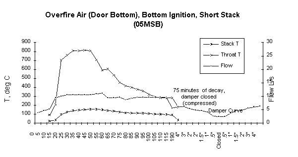
 are
3” firebrick with no lining. For this test the heater is fired from a cold
start (no previous fire). Airflows are low, and from (LK-SEN), we expect
air leakage through the core. Stack temp is measured below the damper at
about 2.5 m and peaks at 156 C. Throat temperatures are measured and shown
on the graph.
At 190 minutes on the graph we see 75 minutes of stack temperature and flow decay compressed into one data point, followed by a damper curve.
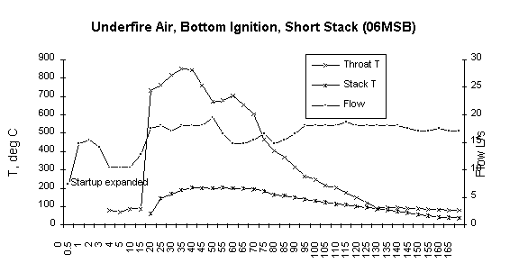
Again, an underfire air “un-retrofit”. Underfire/overfire flow ratio (06MSB)/(05MSB) at 1.8 is similar to heater (SEN) at 2.1. Even with higher excess air, the throat temperature peaks 33 degrees higher because of the faster burn rate. The shape of the stack temperature “areas” on the graphs are characteristic for the two different burn regimes.
This is a Heat-Kit core with a standard clay brick facing. This heater was retested for leakage in (LK-AND). Of all the heaters tested, this installation is most representative of those found in the field. It has underfire air, as did almost all contraflow heaters built in North America between 1985 and 1992. The restrictor on a second air slot in the floor had become displaced, effectively increasing the grate area.
This fire had the highest burn rate of any of the tests. This was evidenced visually by the intensity of the fire, although “airflow in the firebox” might be a better term. The flue gas in this heater travels through a 2 m long heated bench before it enters the chimney. A heavy fly ash buildup was evident in the bench, an indication of very high flow rates.
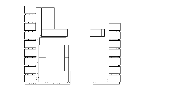
The combustion air system received the standard Heat-Kit retrofit shown below.
The reduction in air consumption from 07AND is dramatic at approximately 75%.
This is perhaps the most interesting heater in the test series. It was
built in 1981 and is the earliest Canadian example of a modern contraflow
heater. It has a set of Finnish double cast iron doors that are ungasketed,
identical to the ones pressure tested in (34DOOR). The air inlet is in
the doors, and there are fold-out cast iron screens behind the doors. The
doors are in mint condition. The identical doors in (34DOOR) were used
for about a year in an underfire air heater, and the cast iron screens
are severely warped due to the lack of cooling by the door air. 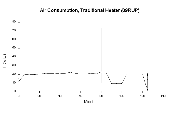 This
heater has been in continuous use for 13 years. Although it has a bypass
damper, the bypass has never been needed for startup. Interestingly, neither
the chimney or the heater has ever been cleaned. The chimney was inspected
last summer and found to still have the red flue liner visible beneath
a very light coating of soot. In a separate test, 27 kg. of hardwood were
burned. The stack temperature was measured at the chimney exit and found
to peak at 110 C.
This is the only heater tested that didn’t have an 18” (457 mm) wide firebox. It has a 22.5” (571 mm) wide firebox. The sliding chimney damper is located on the second floor. A plywood hood was constructed to cover the doors and connect to the DTR, since the air supply is in the doors. The only unaccounted airflows would be leaks through the masonry facing itself, so the airflows from this test and from 08 AND would be the most reliable direct indicators of masonry heater air consumption for overfire air.
At 80 minutes we see the air consumption with doors open (screen closed) and doors and air closed (door leaks only). See full description in data file (Appendix B).
This is a more detailed investigation of sources of leakage in heater (SEN). The standby flow in the chimney is measured by opening the 190x150 (.0285 m2) chimney cleanout immediately adjacent to the heater with the heater blocked off from the chimney. The chimney flue open area is 165x266 (.0439 m2 , 8”x12” modular clay liner). We see a 10.4 L/s flow through the cleanout and a 4.0 L/s flow at the combustion air inlet (cleanout closed).
Next, we install a metal hood that covers both the doors and the combustion air inlet. Standby flow through the open doors is 14.8 L/s, through the open air intake and door leaks (door closed) is 7.6 L/s and through door leaks only is 4.0 L/s.
We then conduct a burn with this arrangement. With the hood, airflows are 1-2 L/s higher than in 02SEN and 04SEN, although outdoor temperature is 10 degrees (C) warmer. The test is terminated at 65 minutes because of overheating problems with the hood.
At 180 minutes with the system hot, we conduct a series of “draft” measurements, using the DTR on detent G (closed) as our draft gauge. These readings are lower than actual draft due to leakage at the DTR foam collar:
| Chimney Clean Out | Firebox Doors | Combustion Air | ||||||
| Flow L/s | Draft Pa | Open
(.0285 m2) |
Reduced (.0077 m2) | Closed | Open | Closed | Open | Closed |
| -6.9 | X | X | X | |||||
| -4.1 | X | X | X | |||||
| -1.1 | X | X | X | |||||
| -10.2 | X | X | X | |||||
| 9.5 | X | X | X | |||||
| 8.2 | X | X | X | |||||
| 20.6 | X | X | X | |||||
| 17.1 | X | X | X | |||||
| 9.2 | X | X | X | |||||
With the system hot, there is an 8.2 L/s flow through door leaks. This is a worst case scenario, since the “torture tested” doors are much leakier than any in actual use. A new set of these doors is tested in (32DOOR), with a leakage of 2 L/s at 25 Pa. The leakage testing of this heater is continued in (LK-SEN) with a flow vs. pressure test.
Next, we conduct another tailout test. In this test, we open the chimney damper and the firebox door 12 hours after closure, at 995 minutes. We insert the thermistor sensor from a digital indoor/outdoor thermometer into the chimney at the damper slot, which is located 4 m above floor level. The sensor wire is quite flexible, so presumably the sensor locates itself in the proximity of the flue liner wall. The graph below shows a three hour temperature decay curve from this point.
We see here some very characteristic features of a masonry heating system: With flow re-established in the system by opening the damper and the door, stored energy in the heater is transported by the gas flow into the chimney. The flue temperature in 4 minutes rises from its standby value of 35.6 C to a peak of 45.2. From there it decays with a nearly linear slope of -2.2 degrees per hour. We see an interesting “ripple” in the curve that starts with an overshoot at 4 minutes, a non-linearity due perhaps to the thermistor electronics or possibly due to feedback effects between the airflow and the heat transfer rate in the heater (This is more apparent in the full page chart in the appendix).
At 180 minutes, the airflow with the doors and damper open is 20.6 L/s. We close the damper and the doors, and when we reopen them 13 hours later at 994 minutes, we still see a flow of 20.0 L/s. With the damper and doors left open and a flow of 20 L/s through the system, the decay in the flow over the next 2.2 hours is 0.4 L/s.
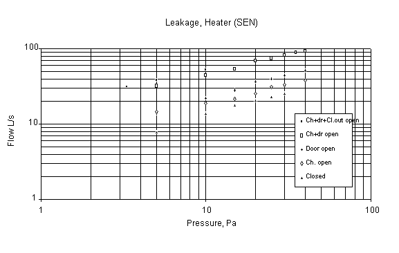
This was a retest specifically aimed at resolving the system leakage question. The air intake was taped closed, and the DTR was taped to the special hood, which was taped to the heater face. The test consists of a series of flow vs. pressure curves taken for a variety of system states: Everything closed, door closed chimney open, door open chimney closed, door and chimney open, door and chimney and chimney clean out open.
The data is summarized quite nicely on a log-log graph of flow versus pressure. At 10 Pa with the doors open we see 22 L/s of leakage. Some of this may be through the chimney damper, which is has a somewhat loose fit. However, we suspect the majority of the leakage to be through the heater core itself, which does not have a “tight” facing.
In order to localize the leakage further, it was decided to conduct a retest on heater (AND), since it wasn’t known at this stage whether the leakage was through the masonry facing itself or through discontinuities in the facing peculiar to heater (SEN).
This is a flow vs. pressure test on a representative current masonry heating system. The system consists of a Heat-Kit core and hardware, and a typical 4” clay brick facing. There is a 2 m. heated bench that connects the heater exit with the chimney. There are 3 cast iron clean out doors and a sliding plate chimney damper downstream of the test hood. The chimney damper is tight.
With a complete facing on the core, we see only 3 L/s total system leakage
(downstream of the hood) at 10 Pa. The facing is expected to be tight because
the space between the facebricks and the core is grouted solid with mortar
in this particular system. However, this is not a general practice with
brick-faced contraflow heaters. Some systems, for example, provide their
thermal expansion control by using a 5 mm mineral wool wrap around the
whole core. 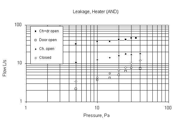
Four masonry heater doors and one cleanout door were tested in a special enclosure built for the purpose. The enclosure itself was first tested for leakage.
All of the doors tested were specifically designed for use in masonry heaters, and are smaller than typical fireplace doors. All of them were of cast iron construction and incorporated a cast iron mounting frame designed to mount onto masonry. All were double doors, and three of the four had ceramic glass. Two of the doors incorporated a cast iron spark screen. Three of the doors were manufactured in Finland by the UPO foundry. The fourth is manufactured in Canada by the author’s company. 31DOOR and 35DOOR were gasketed, with ungasketed air controls. 34DOOR was ungasketed and identical to the door on heater 09RUP. 32DOOR was ungasketed and had a machined fit. The same door is used on heater AND. An old prototype for this door is on heater MSB, and a severely abused specimen is found on heater SEN. Specific descriptions of the individual doors are found on data sheets 31DOOR - 35DOOR.
The loosest door tested with its air control wide open leaked 17 L/s at 25 Pa. The tightest door had to be cracked open 12.5 mm in order to leak 28 L/s at 25 Pa.
Chimney Damper Curves.
A sheet of heavy mylar was taped onto a plywood plate with a cutout. A set of 6 squares was drawn on the mylar. Squares were cut out successively with a mat knife and flow vs. pressure measurements taken. The cutouts were later reassembled with tape and retested using the door test enclosure.
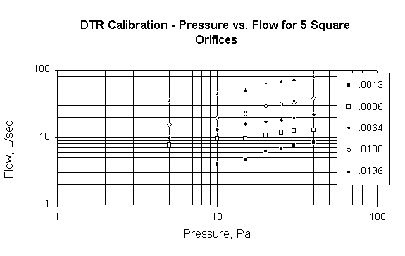
A simple check against theoretical values can be done at 10 Pa. Here, the flow equation reduces to A = Q * .0004(), where Q is flow in L/s and A is the orifice area in m2. For example, the .0036 orifice is in good agreement with this equation, with a measured flow of 9.5 L/s versus a theoretical value of 9.0 L/s.
At moderate airflows the dominant parameter governing flow rates in masonry heaters appears to be throttling of the airflow by the combustion air supply orifice. Air consumption for overfire air masonry heaters tested appears to be under 30 L/s for all test conditions. Underfire air heaters appear to be able to consume up to at least 80 L/s. with 200x300 (nom.) chimney flues. By way of comparison, the 1989 Sheltair reportconcludes, for the fireplaces tested, “these fireplaces do not appear to have a high potential for depressurization of a house during their operation. They operate well with a supply flow rate of about 20 L/s, and appear to have a maximum flow rate on the order of 50 L/s for the sizes tested.”
A useful distinction to make in comparing masonry heater and fireplace models is to regard the masonry heater as a fireplace with a heat exchanger interposed between the firebox and the chimney. For example, Sheltair concludesthat, with an aerodynamically decoupled conventional fireplace, “concentrating all of the (chimney) draft on the intake, and directing the intake air to the woodpile creates an uncontrolled “blow torch” effect, seen both in the lab tests and WOODSIM simulations. ” A masonry heater can essentially “fix” this positive feedback problem in a quite elegant fashion.
A generally accepted value for HDL (House Depressurization Limit) is 5 Pa. In other words, house negative pressure of 5 Pa or less is not considered to be very likely to adversely affect the operation of most naturally vented combustion appliances.
Appendix A details a simulation run in WOODSIM with a fireplace consuming 30 L/s of room air. The ELA for the model was taken from an actual test of an R-2000 house of higher than average airtightness (.015 m2 ELA at 10 Pa). The resulting depressurization was 3 Pa.
It is a common misconception that airtight housing implies poor ventilation. In fact, with mechanical ventilation provided by HRV’s (heat recovery ventilators, or air-to-air heat exchangers), frequent air changes are readily achieved with only a minimal energy penalty. It is interesting to note that a typical HRV penetrates the building envelope with two 125 mm dia. ducts. The “official” ELA used in the WOODSIM simulation was measured with both of these openings taped shut. In fact, the HRV ducts in this example have twice the area of the ELA as it is defined in the R-2000 standard.
All of the overfire air masonry heaters examined in this study consumed well below 30 L/s of air even at peak burn rates. Based on this data, it one could reasonably conclude that overfire air masonry heaters without outside air supplies do not pose a depressurization threat even in airtight houses.
Masonry heaters are currently bound by the outside air provisions in the National Building Code of Canada. There are several reports in the literature of problems resulting from the use of direct connect outside combustion air in fireplaces. Draft reversal in particular has been cited as a potential safety concern for factory fireplaces with low mass, insulated metal chimneys. Due to the different tailout characteristics (see below) of masonry heaters, it is probable that they can use outside air without major risk.
All of the heaters investigated had chimneys that were inside the building envelope. Tailout was investigated with masonry chimneys. Because of the heat storage in a masonry heater and chimney, draft decay during tailout is essentially non-existent. For example, with a typical overfire burn, there is very little indication from a stack temperature curve when the fire is out. In fact, if the chimney damper is not closed after the burn then heat will bleed convectively from the heater into the chimney until the approximately 50 kW-h of reserve is used up. This is most clearly seen in the air flow rates, which remain nearly constant regardless of conditions in the firebox.
It is likely that masonry heating systems with low mass, insulated metal chimneys will exhibit similar characteristics because of the large energy reserve in the heater itself.
A number of masonry heater firebox doors were tested for leakage. Leakage rates at 25 Pa were in the range of 2 - 6 L/s. Leakage data was also obtained on several of the same model doors under actual use conditions.
North American manufactured masonry heaters typically consist of a core that is site-assembled and then faced with a brick veneer. The effect on system leakage of a brick veneer with solid grout between the veneer and the heater core was demonstrated. System leakage would add to the effective ELA of the heater-chimney system and correspondingly higher air consumption and chimney flows. The core system in a masonry heater requires a method to account for thermal expansion, and this is accomplished in a number of ways by different manufacturers. Ideally one should not have to rely exclusively on workmanship in the veneer for tightness. This might be difficult to control, particularly with masons first making the transition to masonry heater construction. One solution would be to develop standard details that would address this issue. Building codes could address this as well. A performance rather than a prescriptive approach would also be an option: at 20 L/s flow rates for example, actual flue gas velocity can be measured inexpensively with a pitot tube inserted into the chimney damper slot.
1) Airflow rates of overfire air heaters were low (<30 L/s). Underfire air heaters had higher rates, up to 70 L/s.
2) Air leakage rates for masonry heater doors tested ranged from 2 to 6 L/s at 25 Pa.
3) Masonry heaters are not susceptible to spillage during tailout, as are some other types of woodburning appliances.
4) Masonry heaters with overfire combustion air are suitable for operation in modern, airtight houses, with or without outside air supplies.
This document was produced using an evaluation version of HTML Transit