| Heat-Kit | Gallery | Brick Oven Page |
|
Bookstore | Library | |||||
| Current Projects |
Contact | Search | Links | FAQ |


During the winter of 2013, MHA Technical Committee members did testing of the new Austrian Eco-Firebox
The performance gains were impressive, particularly the lower emissions.
This firebox reduced particulate emissions by 50% in all 3 heaters tested.
That is twice as clean as a typical pellet stove.
Austrian specifications for firebox.
Time lapse of run GH-18
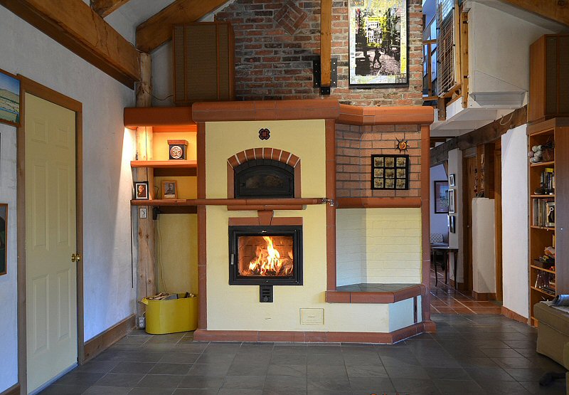
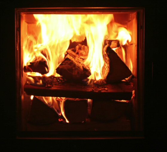
Photo story below shows a retrofit of this firebox into our own heater. Using a Bosh SDS rotary hammer, a series of holes is started on the right edge of the terracotta door trim. We need to enlarge the opening to accomodate an air frame to feed the new air system. Widened opening. The firebox liner bricks are removed. A heavy duty shop vac with retrofit HEPA filter is run continuously to control dust. A fan is installed in the outside door, to depressurize the room and control the air flow to eliminate fine dust. An appropriate air inlet (door or window) is selected to produce a cross draft. The opening is also lowered. To prevent stray combustion air leakage into the exhaust channels, the firebox is sealed with a coat of refractory mortar. The mortar is applied with a sponge to work it into any cracks or open joints. The facing brick door jambs are repaired with regular mortar, since temperatures will be low there with the air frame. Note the wear on the angle iron brackets that hold the heat shield bricks to protect the steel lintels. We have switched to stainless steel for these brackets in current heaters. Air inlet at bottom of door is configured. New lining firebricks are numbered for easy installation. The air frame will be fed from the bottom. Air inlet into the heater is directly below. There is a pivoting air shutoff in the existing base slab, which allows for ashes to drop and optional outside air. These are closed off. The new system will be airtight, and eliminate the sliding chimney damper. There is no air at the bottom of the firebox. 5mm horizontal air slots start on top of course 2. They are created by setting the bricks on shims. Starting the horizontal air slots. Finished firebox liner. Trial fit for air frame. It is contructed of 3"x4" steel tubing. See testing link for details. Note the gap between the air frame and the liner, which will have to be filled. Looking towards the bottom of the air frame from inside the firebox A layer of firebrick splits will cover the deteriorated firebox floor, and also seal the air gap at the front. 1/4" thick ceramic paper gasket goes underneath the air frame. Air frame is installed, and temporarily wedged tight with metal shims between the frame and the steel facing lintel. The gap between the frame and the steel lintel is packed tightly with ceramic fiber. A bead of silicone is installed, partly as an experiment since this will be the hottest exterior portion of the air frame. My money is on the silicone. New firebox floor. The gap between the air frame is packed with ceramic blanket, until we develop a better detail. The gap on either side of the air frame is pumped full of silicone. This will be the fastening mechanism. We were planning to use the 3/8" bolts + long nuts used for new construction, but decided to try this. Door is installed into the air frame. It has a groove for a gasket rope on the rear of the door frame, which seals it to the air frame. The door was fitted to the air frame beforehand in the shop. 1/4"x20 threads were tapped into the air frame, and stainless machine screws are used to fasten the door. Beautiful top down burn. The fire is a little slower, and top down ignition seems to work better than side ignition. The pile burns very evenly, and does not fall over.  March 2016: updated facing |
This page last updated on May 13, 2016
This page was created on November 22, 2014