The images here illustrate certain points of interest during a project in the department of Seine et Marne. A full core construction sequence is detailed in Refractory Core Construction Sequence. 2006
The core would have an upper chamber oven and active bench running off the right side channel.
Detail: Active bench. Fire box floor. Installation of Thermocouples.
Note: Any images or notes regarding projects inspired or assisted by this article, if sent to Pyromasse, will be posted on to a page specially created for such comment.
See also: Technical Documents PDF Index

My place of abode during the project.
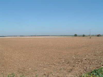
The lay of the land.
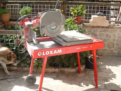
The saw used on this project. 350mm diameter blade. Guillotine action. Rolling table.
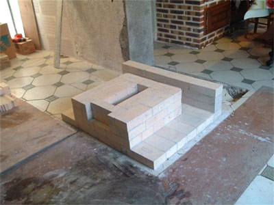
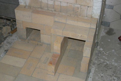
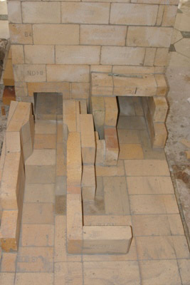
The first 4 rows of refractory brick.
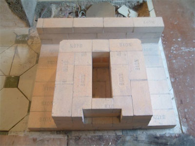
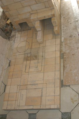
Side and rear manifold. The central opening is for the grate and ash drop. The chase at the front of the core is to allow primary combustion air to flow up to the fire box.
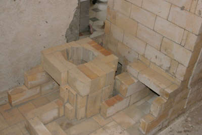
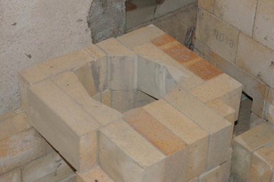
View of the right manifold
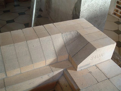
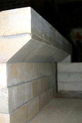
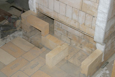
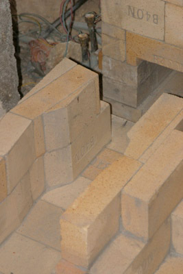
The angled fire box floor created here forces the embers together over the grill, and so accelerating the end stages of combustion.
It also consolidates the courses below and provides a strong stable base for the fire box walls.
It also consolidates the courses below and provides a strong stable base for the fire box walls.
The two bricks which form the back corners of the fire box floor have to be sculpted using a grinder.
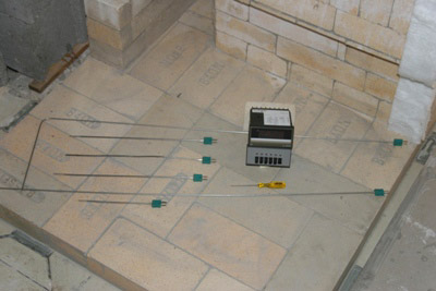
The full set of thermocouple and monitor.
The kit consisted of 6 thermocouples of various lengths.
The kit consisted of 6 thermocouples of various lengths.
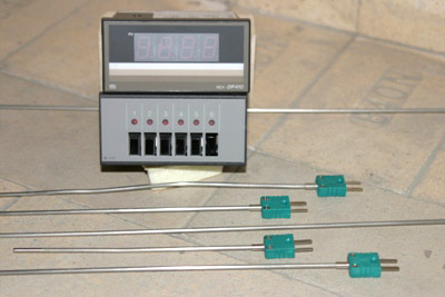
A more detailed article regarding the exact location of all 6 thermocouples, and a correlation of temperature readings received from them, will follow.
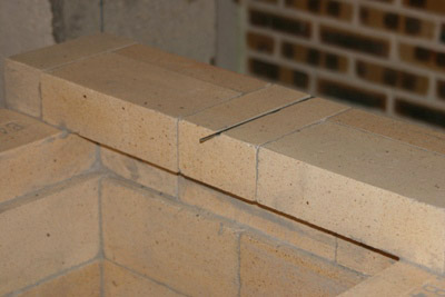
The first thermocouple was located between the second and third corbelled courses of the firebox ceiling.
A groove is cut in the brick to accommodate the TC which is loose and can easily be removed.
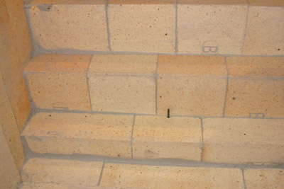
The second thermocouple between the oven's load relieving lintel and the course of brick above.
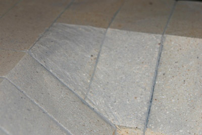
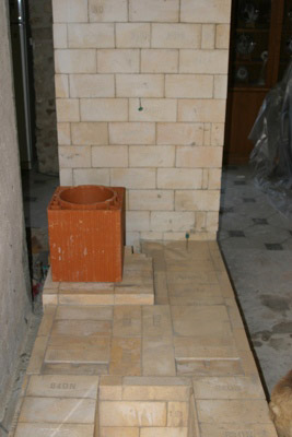
The bench is traced on to its base.
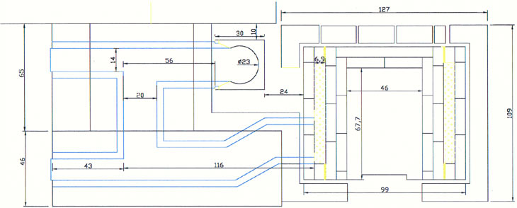
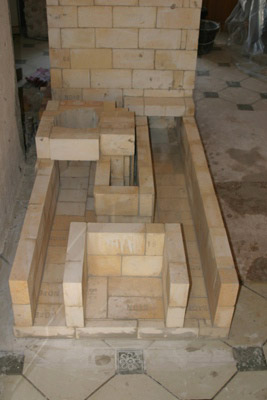
The gases will exit the heater from the opening at the right travel through the bench and enter the chimney at the point circled. The opening to the left is to allow the heater to feed directly into the chimney and bypass the bench.
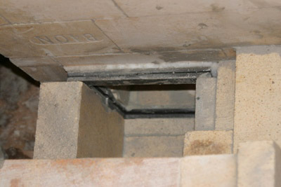
The two openings in the side channel.
Note the cut out in the base in front of the bypass opening. This is to accommodate the Upo 8 inch x 8 inch cast iron sliding damper.
Note the cut out in the base in front of the bypass opening. This is to accommodate the Upo 8 inch x 8 inch cast iron sliding damper.
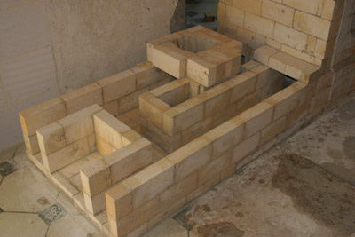
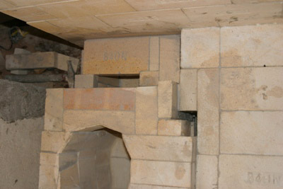
The two openings bridged and the start of the side channel bench.
The bench walls directly beneath the chimney must be strong enough to take the weight of the chimneys flue tiles.
Detail of bench walls at the chimney connection.
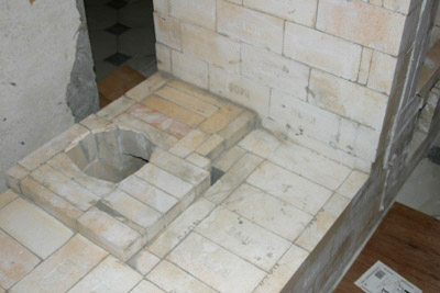
The chimney connection platform.
The first flue tile 8 inch interior diameter will rest directly upon the platform.
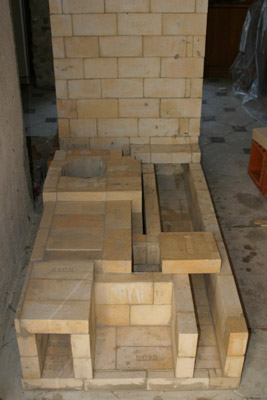
The bench walls. The two openings at bottom are clean out, allowing access through the bench to the manifold of the heater, and through the bench to the chimney connection, and on through the by pass to the rear manifold.
Detail
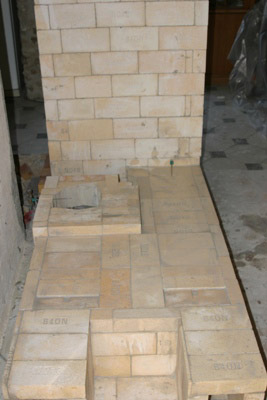
The bench almost closed.
9x9 inch refractory tiles were used to bridge the corners.
9x9 inch refractory tiles were used to bridge the corners.
Detail
The first flue tile in place.
The cast iron frame of the bypass sliding damper. When open the heater will feed directly into the chimney, when closed, the gases will be forced to take the longer path through the bench to the chimney.

The frame plate is held tightly in place by the adjoining masonry. A mineral wool gasket between the frame and the side channel allows for a limited amount of play.
The bypass is bridged.
The masonry, above the bypass, is brought up to the level of the chimney platform.
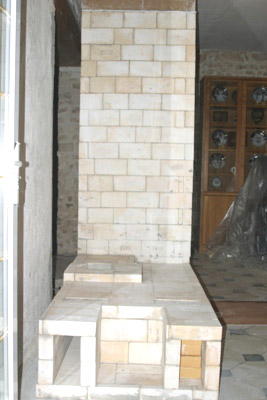
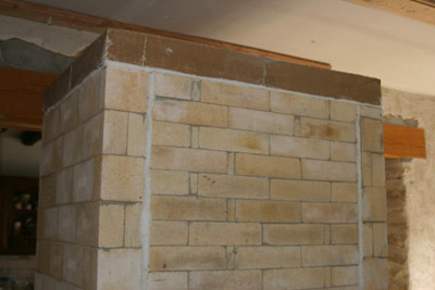
The finished core and bench.
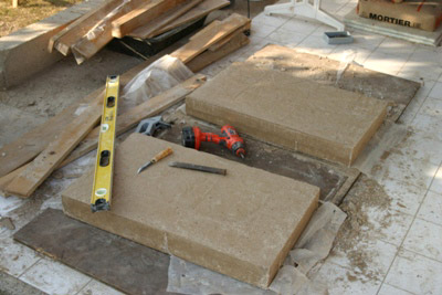
The two castable refractory capping slabs used to close the core.
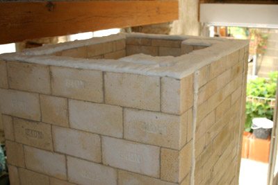
The final course of the core with ceramic wool gasket, ready to install the capping slabs.
The two slabs, though essentially free floating, are mortared together.
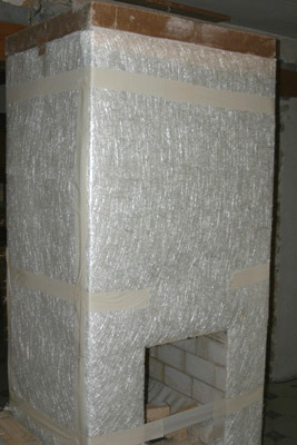
The core with its fibreglass mat gasket, ready to be faced.
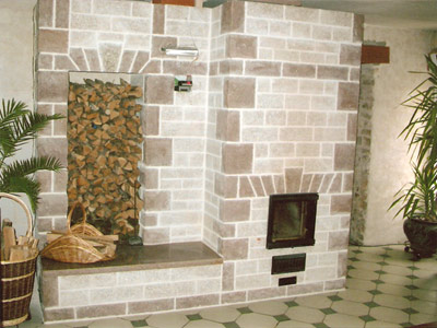
The finished project.
Marcus Flynn
13 March 2007
