The following images and text detail the construction of a
Finnish style contraflow refractory core in Quebec.
The intention of this article is to give a course by course account
of the construction of the core and upper chamber oven.
I began my trade by learning to build the standard Finnish
contraflow heaters. These heaters have a smooth sloped fire box
ceiling, and a narrow throught. An expansion chamber after the
throght uses the Venturi effect to mix air, gas, and flame,
resulting in secondary ignition.
Due to my own observations and experience, and influence from
Norbert Senf, for the last few years I have been building cores
in a different way.
The fire box ceiling does not have skew cut corbels, but full
bricks, making the ceiling look stepped.
These corners on the corbel cause turbulence which promotes
mixing and secondary ignition. The fact that full bricks are used
in the corbel make each corbel stronger. There is also a
considerable saving in time. The only reason for a sloped (smooth)
fire box ceiling could be to ensure a smooth draw. All heaters I
have built have drawn extremely vigorously, and so drag from the
corner of the corbels is unlikely to have a significant
effect.
This core does not rely upon the Venturi effect to assist
secondary ignition. No air is drawn up through the grate (under
air). Primary air is drawn through a channel between the core and
facing and deflected (as over air) onto the wood load at a 80
degree angle.
The above variations from the base design are considerable, other
differences are no more than my choice of how to build.
I have built many cores to this design and can say that they heat
as well if not better than those I built to the traditional
plan.
The core is built with Mount Savages High Heat and Super Duty
brick layed in Super high mullite mortar. The castable refractory
concrete is Mount Savages Heatcrete 24 esc. Ceramic wool RT 6.
and ceramic Paper, Roolboard are by Vesuvious.
Note: Any images or notes regarding projects inspired or assisted by
this article, if sent to Pyromasse, will be posted
on to a page specially created for such comment.
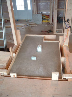
Foundation slab is poured on to an elevated foundation in
block. The chimney will be at the rear left.
The two forms of expanded polystyrene are to create an air
intake (at front) and an ash drop (rear) opening in the slab.
The foundation and its slab have a two inch clearance from all
the combustible structural portions of the surrounding floor.
The first 5 rows of common clay brick are layed up in type N
mortar.
The rear wall of the rear manifold is layed in refractory
brick, the flue conection negotiated, and the first of the two
courses that will form the hearth layed. This course represents
the change in manifold width of 12.5cm reduced to the side chanel
width of 6.5 cm.
The opening, in the rear manifold, for the clay liner tile
which will connect the heater to the chimney.
This is a potential week spot and work on or around it needs to
be done with care.
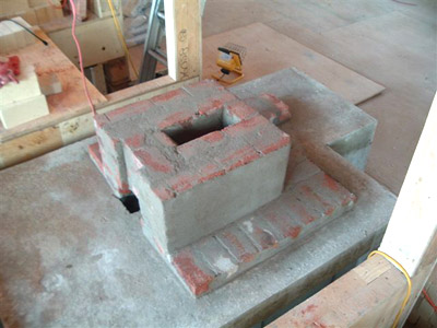
Second course of Refractory brick . This row is important as
it solidifies the row beneath that bridges the rear manifold.
Note: the interior bricks of the hearth, around the cut
out for the grate, are super duty.
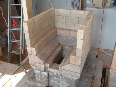
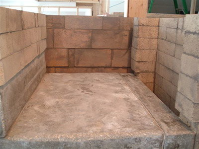
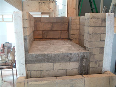
The angled hearth. The sloped fire box floor helps coral the
embers over the grate and accelerate the end stages of the fire.
This enables the damper to be closed sooner, reducing heat
loss.
The angled hearth with cut out for Upo 1413 cast iron grate. This
portion of the work is all in super duty brick.
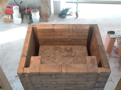
The first course of the fire box. The inner wall is in super duty
and the outer in high duty brick.
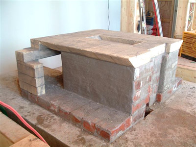
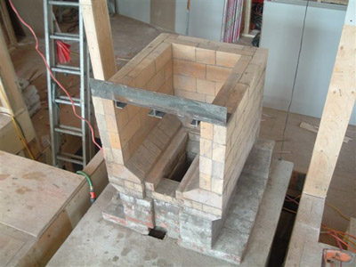
The outer wall of the fire box completed with only the first
course of the inner wall layed.
Note: the recess cut into to the brick of the last
course. This will seat the angle iron lintel used to span the
fire box opening.
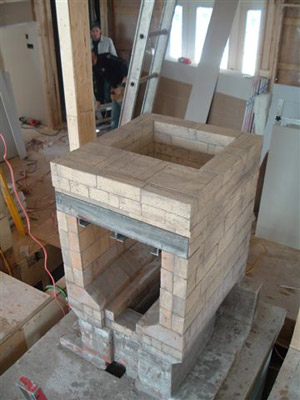
The inner fire box wall complete and the angle iron lintel in
place.
The inner wall of the double wall fire box wall can be removed
and replaced if necessary in the future.
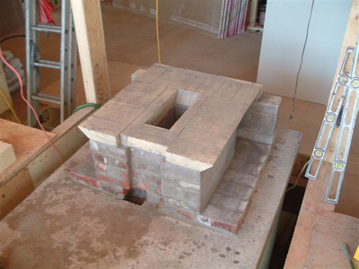
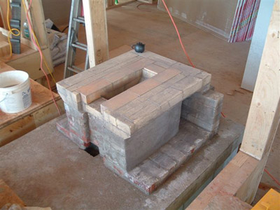
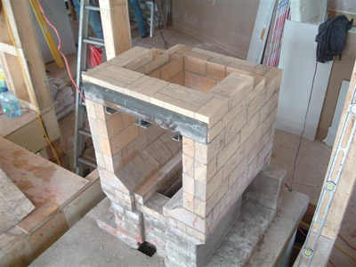
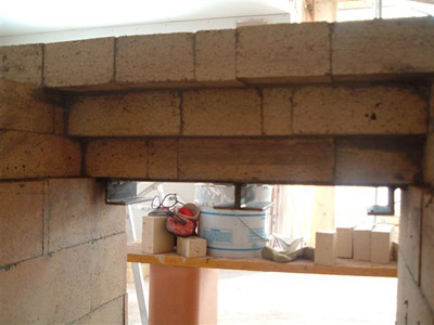
The first two rows of corbelling of the angle iron lintel.
The first three courses over the lintel are of crucial
importance, and the bond employed needs to be carefully
considered.
The fire box ceiling closes in on the rear wall with every
corbelled row.
The first three corbelled rows above the angle iron.
It is at this point that the heater can suffer the most
stress.
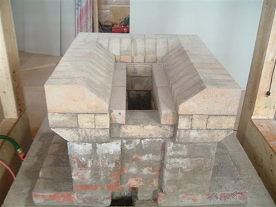
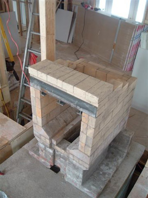
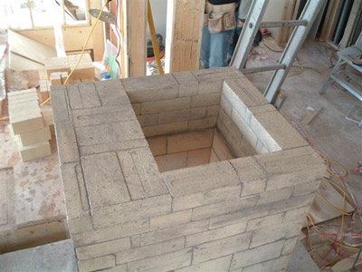
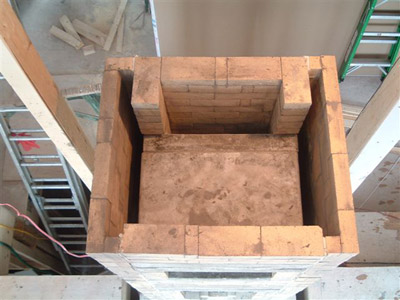
Five courses above the lintel closing in towards the fire
tube.
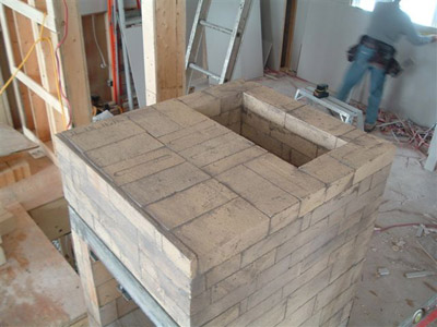
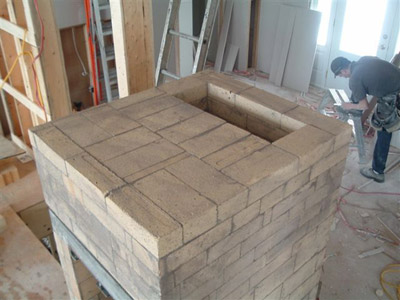
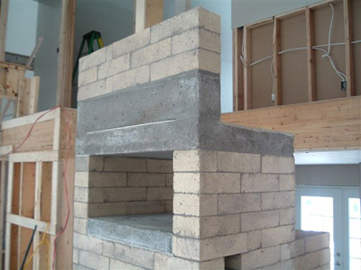
The sixth and final course before the under hearth channel of the
oven.
The ovens under hearth channel.
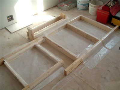
Molds for the modules that will form the oven, prepared with
polyethylene, ready to be poured with castable refractory
concrete. From left to right Hearth Slab, Top Slab, Backslab, and
load relieving lintel at the rear.
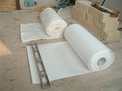
RT 6 Ceramic wool and Roleboard one eighth of an inch ceramic
paper (in the foreground) The wool is used to form the smoke and
expansion gasket between the core and the side channel walls and
is useful as a smoke gasket around chimney connections.
The paper is used between each of the refractory concrete modules
that form the oven. It provides an expansion and smoke gasket.
All the ovens modules are free-floating, and the bake chamber
free of smoke.
The finished core. Before building the side channels a gasket of
ceramic wool is affixed to core with refractory mortar.
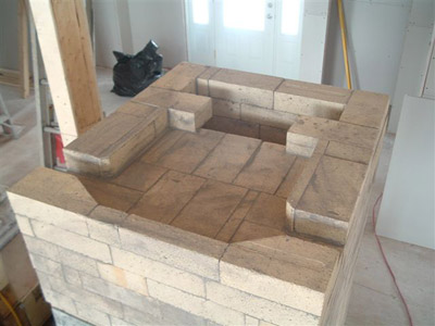
The ovens hearth, side walls, top slab, and load relieving
lintel.
The rear slab of the oven is not yet installed.
The rear faces of the oven's side walls, hearth, and top slab,
with role board gaskets. Ready for the installation of the rear
slab.
The oven's rear slab in place and the start of the rear wall of
the fire tube. The hot side of the slab is also gasketed with
role board.
The rear wall of the heater that forms the fire tube holds the
ovens rear slab in place.
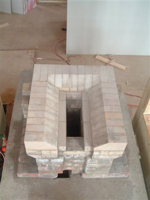
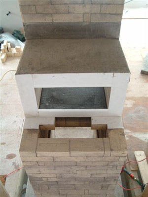
View into the upper chamber. The left side channel is
complete.
View from the rear as the right side channel is built.
View under the oven's under hearth channel to the left side
channel beyond the exit opening.
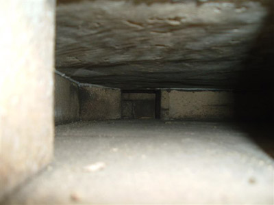
Looking down the left manifold from the corner of the rear
manifold (through the chimney conection). The manifold access
opening is seen in the side channel wall right of center.
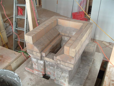
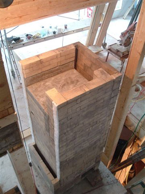
The core with only the right side channel to lay up.
The right side channel almost complete
View inside the right side channel.
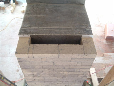
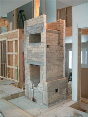
The core (looking from the back) ready to have the two castable
refractory concrete capping slabs installed.
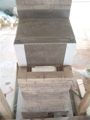
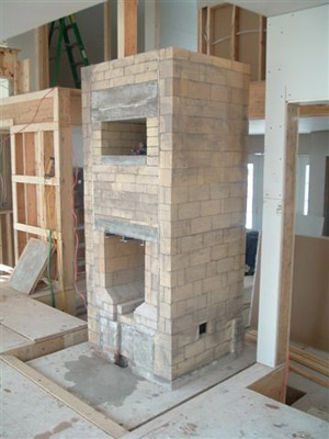
The upper chamber from the front. Looking down on to the two side
channels and the fire tube.
The finished core, still without capping slabs.
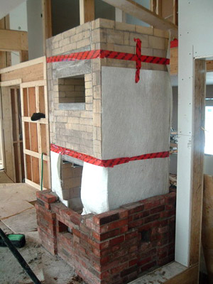
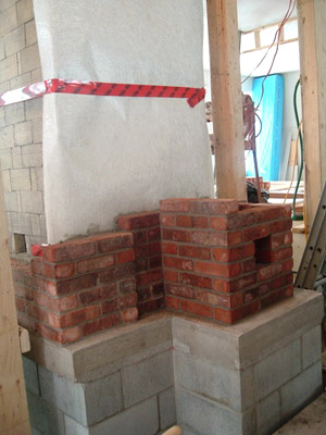
The first courses of clay brick facing.
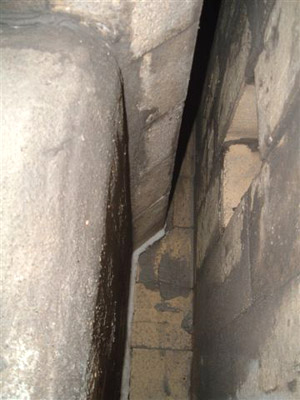
Glass fibre mat is used as an expansion joint as opposed to
cardboard or mineral wool.
The front and back faces of the core are covered with 4 sheets
of mat that form an expansion joint, and the side faces 1 sheet,
which acts only as a slip joint.
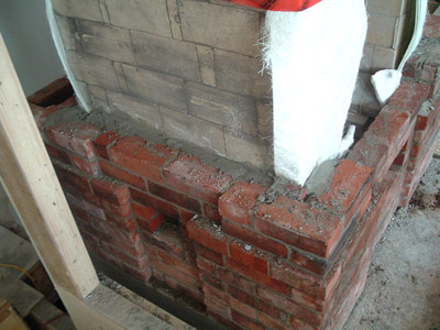
The chimney connection at the back of the heater.
Back fill between core and facing is a serious affair as it
assists heat transfer. The side face does not have its mat
installed yet as at the bottom of the heater , where it will be
cooler, expansion is not a problem.
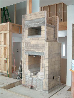
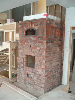
The core before its Refractory concrete capping slabs are
installed.
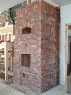
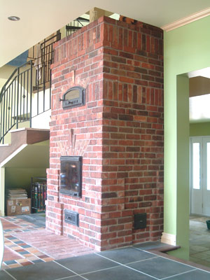
The facing finished. After the chimney has been built the
brickwork will be brushed, washed with acid, and then rinsed .
The last step will be the installation of the hardware.
Pyromasse, Montreal. April 2006