
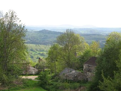
The site is situated in a small hamlet in the Massif de Megal Haute Loire, about 2 km from the ancient pilgrim road to
Santiago de Compostella .
It is recommended that the article Community Ovens in the Massif de Megal be read before the following account.
It is recommended that the article Community Ovens in the Massif de Megal be read before the following account.

Detailed are:
- The construction of a contraflow refractory core.
- Indirect or black oven.
- Expansion gasket between core and facing.
- Aesthetic details in volcanic rock.
- The connection to the chimney via a short section of bench.
See also phonolith chimney caps
Materials
Refractory Brick
Bony B40N
HTC
Refracol 1
Castable Refractory Concrete
Refcast 1460 10
Wool
Thermal Ceramics Super wool
Flue Tile
Terracotta 230 mm round
Volcanic Rock
Phonolith and Basalt
Clay Brick
High density Terre Cuite de Berry
Hardware
Upo
Expansion joint
400g Glass Fibre Matt
See Technical Documents PDF Index
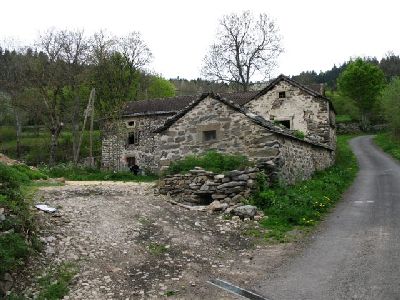
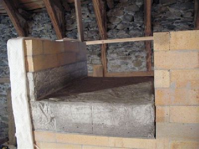
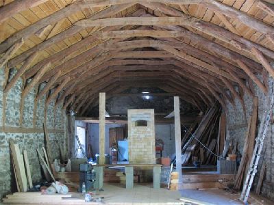
The farm has been built over the last 3 centuries, though the form visible today dates from the 1820's
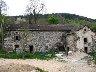
The heater would be built on the upper floor of the barn just to the right of the open window in the top left of the wall.
The barn walls are 1m thick consisting of irregular rock and rubble layed in clay mortar.
The interior surfaces of its walls will be insulated with hemp and lime plaster.
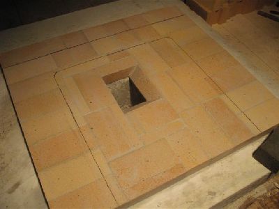
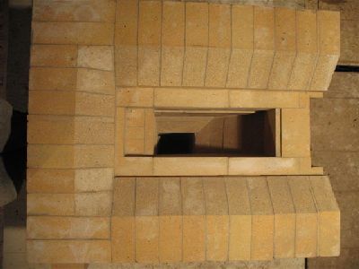
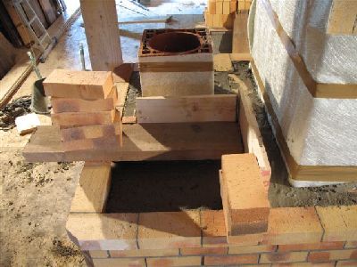
The base course of the core with the opening for the ash drop.
The pencil line represents the limit of the inner face of the side and rear manifolds
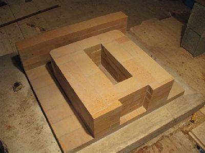
The first three courses of the core base and the rear manifold wall.
Note the primary air channel recessed into the front face.
Note the primary air channel recessed into the front face.
View down the ash drop opening.
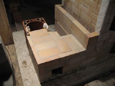
The two rows of the hearth.
Overhead view of the finished hearth.
The sloped hearth floor before construction of the fire box walls.
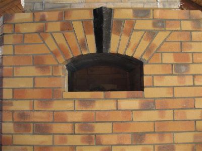
View up through the fire box ceiling towards the throat. The firebox loading opening to the left,
the ovens loading opening to the right.
The ovens top slab and load relieving lintel
In this situation the slab was cast with a curved interior surface at the request of the home owner
A flat slab ( link to Further operations in Auvergne) would have been better for the following reasons.
When working in the field with limited forming material;. In order to assure that the mix has the right amount of water , and that the poured castable is vibrated into place and adequately protected against evaporation during the reaction, a flat mould must be made. The curved interior surface can be formed easily but the outer face or extrodus of the arched slab cannot be curved , without the mix slumping flat during vibration. If the upper surface is trowled into a curve then the mix cannot be vibrated and slab will be ultimately sub standard.
With a curved interior the middle of the slab, which takes the full force of the hot gas is only 3 inches thick, while the outer portions of the slab, which rest upon the oven walls are 5 and a half inches thick.
The gases which will follow the path of least resistance will tend to flow in concentration over the middle , thinnest portion of the slab.
With a flat slab the overall thickness is even at 4 inches, and the gasses forced to flow evenly over its whole inner surface. Thus providing a more equal transfer.
The last difference may be relatively slight. For my self the priority is to cast a durable strong slab. The one advantage of the curved slab is that it shields the rear faces of the voussoir in the facing where it arches over the loading opening, making the manufacture and installation of a custom heat shield, for the voussoir, unnecessary.
The flat top surface of the slab may cause an accumulation of ash which would insulate to an extent, though it does provide a level bed for the load relieving lintel.
A curved top to the slab, would prohibit the accumulation of fly ash, but make the installation of a load relieving lintel difficult.
In a workshop environment and with the right forming materials it would be possible to cast a top slab curved on both upper and lower surfaces, with a level platform to accommodate the load baring lintel, at the front of the upper surface.
In the field with the limited materials available this would be inpractical.
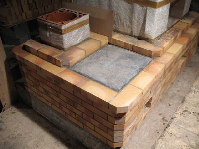
The flat upper surface of the ovens top slab.
The slab contains 115 kg of dry castable.
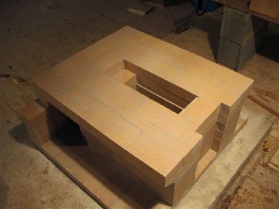
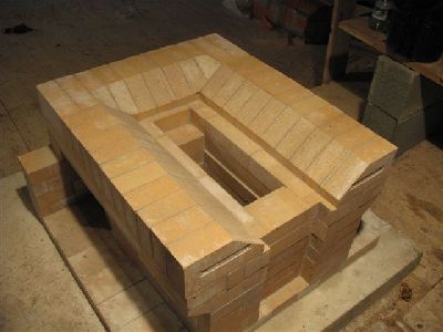
The completed core, before construction of the side channels.
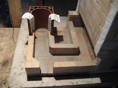
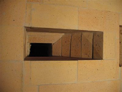
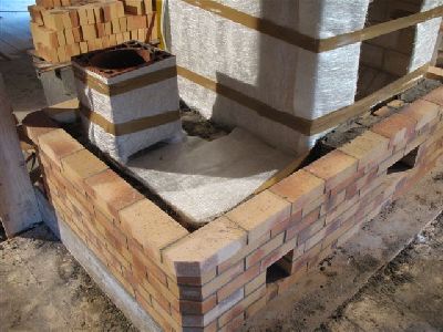
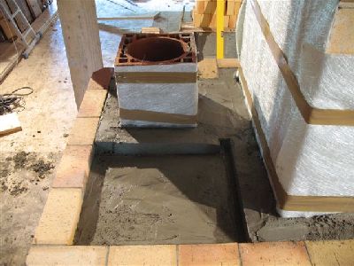
As there was room available on the foundation slab, rather than connecting straight out of the manifold into the flue tile,
a u-shaped section of transmission tunnel, or extended smoke path is built. This also permitted straight access, and vision,
through the inspection opening in the tunnel wall, without having to cut a second opening into the flue tile.
This section of extended flue is two courses of brick high and 19cm wide. The interface between brick and flue tile is
gasketed with wool that serves as both an expansion, and smoke gasket.
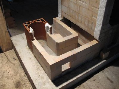
The tunnel is capped an the side channel built around and over its opening from the manifold.
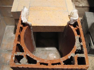
There is no solid physical contact between brick and tile.
The tiles diameter is 230 mm
The tiles diameter is 230 mm
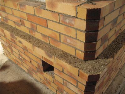
Front view of the finished core and side channels.
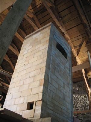
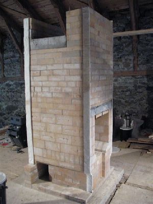
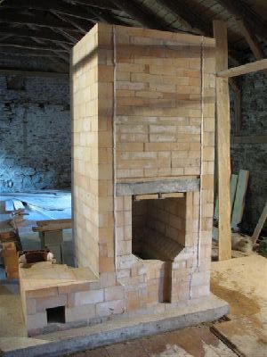
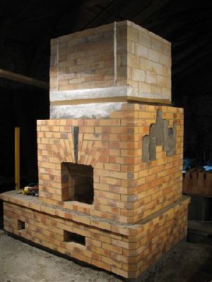
The core before facing.
Having difficulty dominating the space.
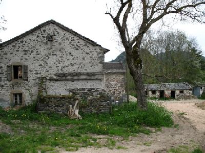
Note: The seemingly excessive carpentry of the roof structure is to support the weight of the phonolith Lauze used as roof covering throughout the region.
Having difficulty dominating the space.
Note: The seemingly excessive carpentry of the roof structure is to support the weight of the phonolith Lauze used as roof covering throughout the region.
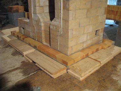
The first row of facing brick are layed dry to determine the overall lay out of the brick work.
When laying the brick out, about an inch and a half of space is left between the core and the back of the brick to accommodate
the expansion gasket and any ‘strong’ deviation off plumb in the upper portions of the core. It is preferable to leave a little
more space than to have to saw the back of several rows of brick to accommodate the core being off plumb.
Excess space will be backfilled with mortar as the facing is layed.
Even if the core is perfectly plumb, the width of the facing brick may vary. And a brick that is just touching the gasket will still inevitably have a small air space between it and the gasket, that will reduce transmission efficiency.
Tightly compressed backfill means that there will be no space of trapped air between the back of the facing brick and the gasket, or the gasket and the core.
If the space between the back of the brick and the gasket is less than a quarter inch then backfilling effectively without tearing the gasket and destroying its integrity is difficult if not impossible.
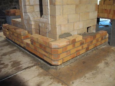
For purely aesthetic reasons the first 7 courses of brick will be layed 2 and a half inches further away from the core than the rest of the facing.
This extra thickness of the facing would be detrimental to the overall efficiency of the heater were it continued, but at this level its effect on transfer
efficiency is negligible, as the lower portions of the heater are relatively cool. The wooden boards are used to support the first row of brick, as the brick
rest more than one third of their with beyond the limit of the raised foundation pad.
Once several courses of brick have been layed the support boards are carefully removed.
The weight of the subsequent retracted facing which will rest partially upon these courses, and partially upon the back fill behind, will hold them in position.
The weight of the subsequent retracted facing which will rest partially upon these courses, and partially upon the back fill behind, will hold them in position.
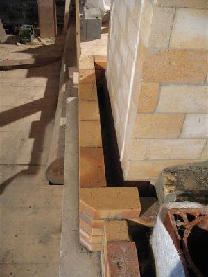
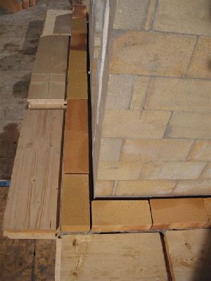
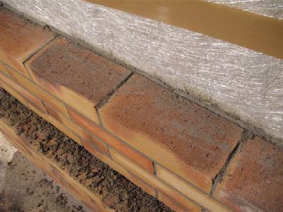
The space of approximately two and a half inches between the core and the first 7 courses of facing, before installation of the expansion gasket
and backfilling.
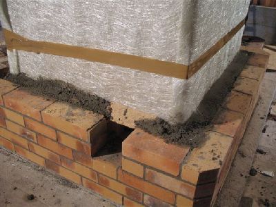
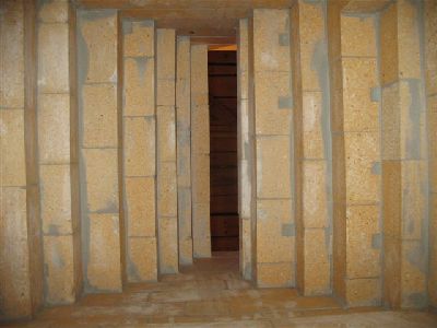
The expansion gasket consists of 400g fibreglass matt, held in position with parcel tape.
In this image front and back are left and right respectively and top and bottom the two sides.
On the front and back where, expansion is considerable, there are three layers of Fibreglass matt, and on the sides, where there is no expansion, a
single layer. The layer on the sides acts primerally as a slip joint, preventing the backfill from bonding to the side channels Though there is no lateral
expansion from the face of the side channel a strong bond between facing and channel could cause the facing to be lifted with the vertical expansion
of the channel.
Note that the gasket on the front and rear is wrapped around the corner onto the sides in order to reduce the risk of backfill causing a mechanical
bridge on to the corners of the channels.
The transmission tunnel and flue tile are gasketed with a single layer of matt. The top surface of the tunnel though has two layers.
The concrete poured onto the the top of the tunnel will bridge on to the the ledge behind the last row of corbled facing brick. This ledge is not gasketed to allow a solid support for the poured concrete. Thus the whole transmission tunnel will be free floating, having no physical contact with the facing or the concrete.
The concrete poured onto the the top of the tunnel will bridge on to the the ledge behind the last row of corbled facing brick. This ledge is not gasketed to allow a solid support for the poured concrete. Thus the whole transmission tunnel will be free floating, having no physical contact with the facing or the concrete.
The concrete is poured to two inched below the top of the last row of corbled brick, in order to leave room for the insertion of a piece of phonolithe
that will be used to finish the top surface of the tunnel. The boards held in place with bricks act a shuttering to allow a greater thickness of concrete to
be poured, as lintels, where the facing of the heater and chimney will bridge the tunnel.
The Phonolith can now be layed into the recess and the facing brick layed on the lintels.
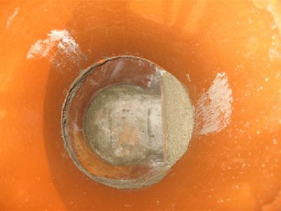
View down the first two flue tiles showing the concrete that was poured onto the tunnel at right. The concrete flowed on top of the tunnel and
under the lower rim of the second tile, offering some support for it.
The concrete lintels were formed slightly less wide than the with of the brick . The piece of phonolith was layed into the recess and then the first
course of the heater wall and chimney layed on top.
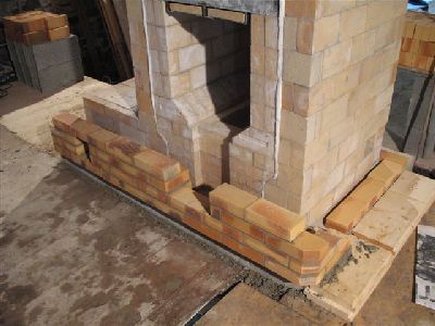
Once the expanded first 7 course has been layed the facing is retracted to its final position one half inch from the gasketed core. This half inch
space is backfilled.
Sand is sprinkled onto the upper surface of the corbled course to avoid it being stained by falling mortar.
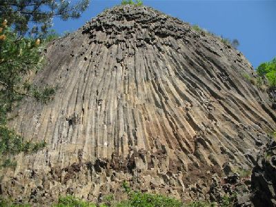
As the site was situated in a region of intense recent volcanic activity, and actually in the shadow of a trachyte suc, it was decided to try and
locate some suitably sized trachyte prisms to install in the heaters facing.
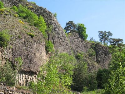
All the prismatised trachyte was in too large a format to be used on the heaters facing. We did though manage to find this basalt flow from the
foot of which we were able to gather many suitably sized basalt prisms.
The flow is located about 35 km from the site.
The flow is located about 35 km from the site.
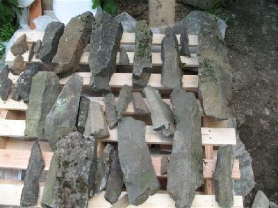
The stock of basalt prisms gathered on the expedition.
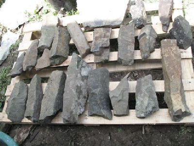
Basalt is extremely dense and renowned for being undressable with hand tools. Compounding this the prismatisation process has seriously
weakened the rock. Even the vibration of the saw was enough to cause many of these pieces to crack or shatter.
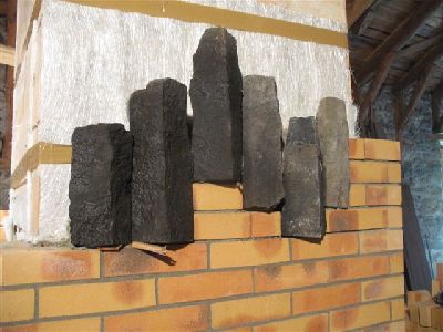
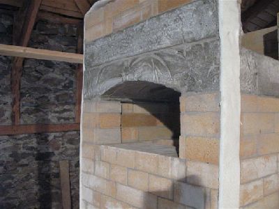
Six prisms were installed in to the facing, in a manner of alignment not unlike that in which they would occur in nature.
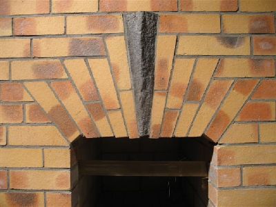
The key of the arch spanning the firebox loading opening was also cut from a prism.
Though of igneous origin basalt is renowned locally for shattering under even light thermal shock.
Obviously the use of this material in this position is risky.
Obviously the use of this material in this position is risky.
The core half faced.
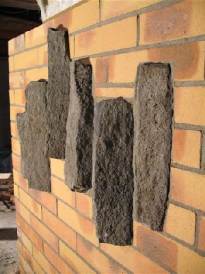
The prisms were installed in the sense that they formed, that is, perpendicular to the ground, and with the slightly narrower top pointing up.
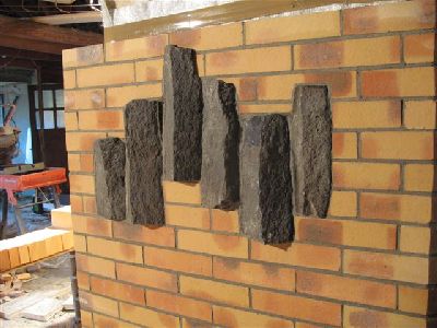
Approximately half the volume of each prism protrudes from the facing.
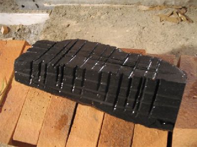
The basalt prism used as the key in the arch over the oven loading opening. The rear and sides were scared with the saw to help the surrounding
mortar hold it in one piece should it crack.
As this piece may at some point crack or even shatter the key is backed up with a key of refractory brick. Even if the basalt were to disintegrate
the arch will not fail.
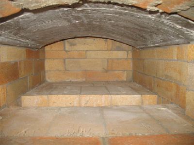
The interior of the black oven before installation of the door.

View inside the upper chamber , showing the top of the oven, before installation of the capping slabs.
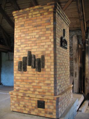
The last 4 courses of the heater had to be finished in a different brick. Originally the heater was to be rendered and so brick were slightly unordered with the intention of making up with local brick.
Marcus Flynn
2008
