Oost Vlaanderen
These notes document the construction of a North American contraflow Taaka in East Flanders. Detailed are; black upper chamber oven, fire box liner, and transmission tunnel.
.jpg)
Terraced dwellings transmitting the local vernacular.
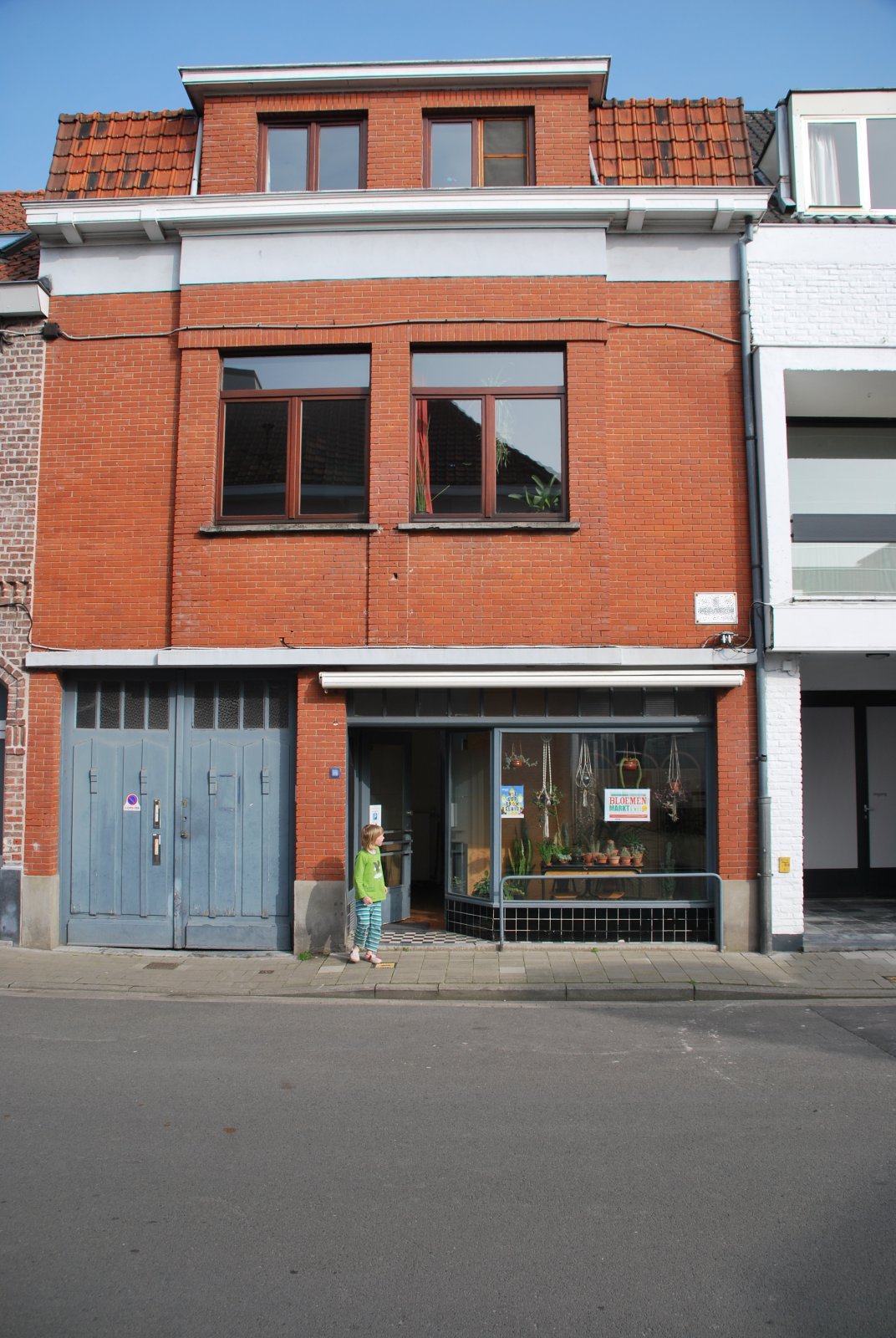
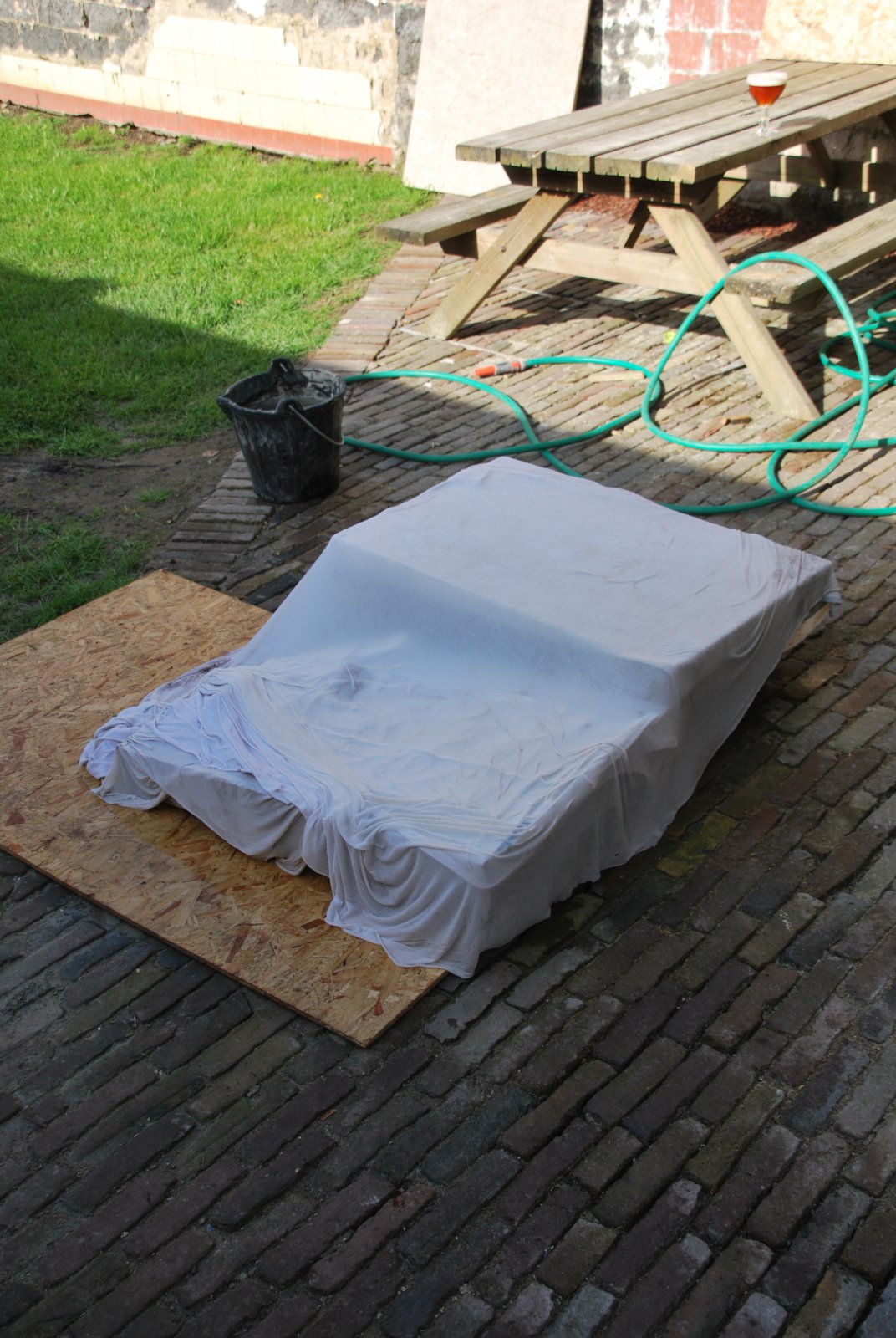
The stove will be built on the ground floor of this former horse butchers shop.
It will be situated against the tripple wythe brick wall, separating the house from that of the next door neighbour at right.
It will be situated against the tripple wythe brick wall, separating the house from that of the next door neighbour at right.
.jpg)
The stables and smoke house at the back of the shop.
Materials
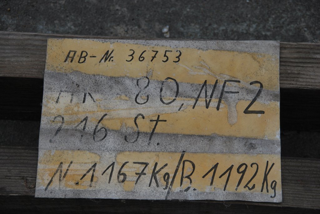
Brick:
High Duty. NF2 Format.
HTC:
Refracol 8.
Castable:
Reracol. Cast 550/10.
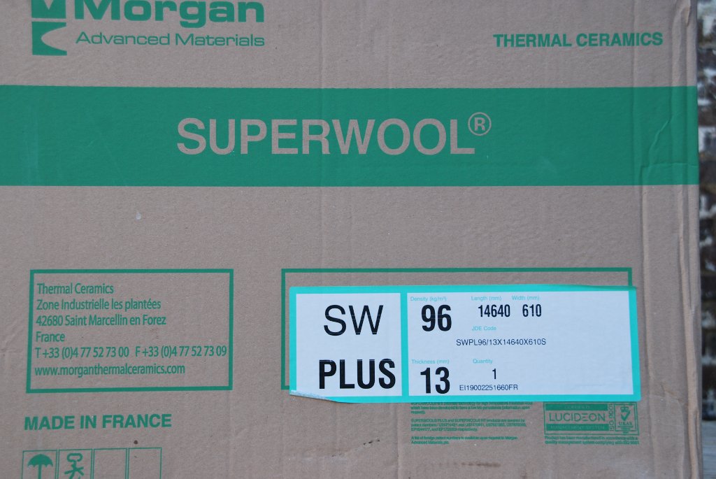
Ceramic Blanket:
Thermal Ceramics Superwool Plus.
Ceramic Felt:
Flue tile:
Refractory Clay 20 cm square inside dimension.
*
.jpg)
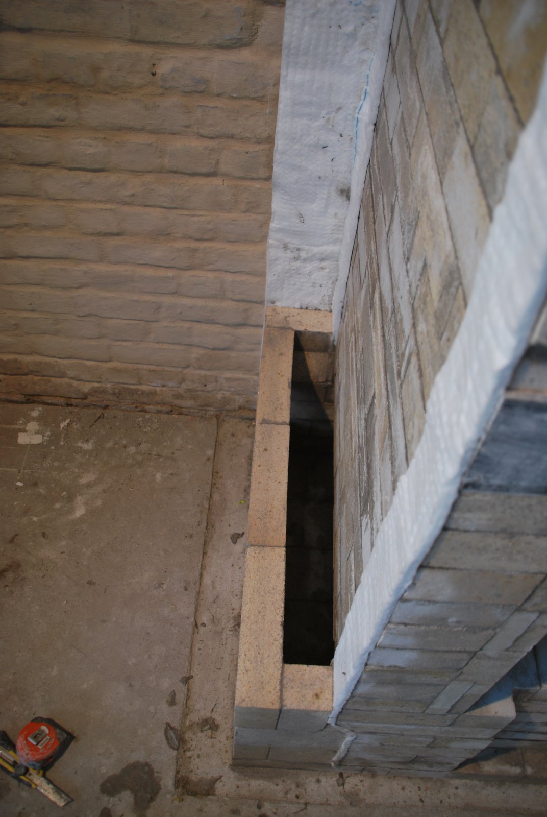
The core will be built upon an elevated concrete foundation, which will also act as an ash drop. The tripple wythe wall will form the rear facing of the stove. This location is far from ideal as there will be transfer of heat into the wall, and the uninsulated, unheated, neighbours garage on the other side. This location was chosen by the homeowner, in order to reduce the space that a free standing, centrally located stove would occupy.
.jpg)
2 layers of 13mm wool are taped to the brick wall as a thermal break.
.jpg)
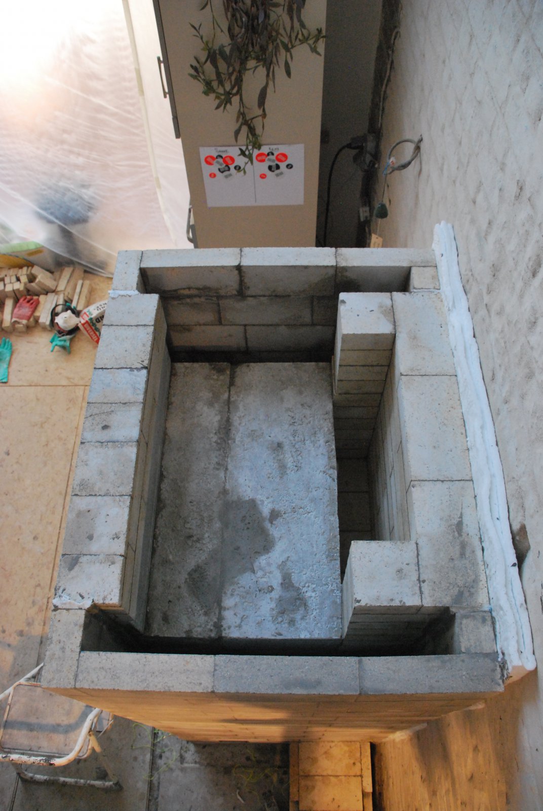
The first 4 coures of the core and rear manifold walls. A supplementary underair channel is cut out from the front of the core to the ash drop.
.jpg)
The fifth course covers the under air intake path.
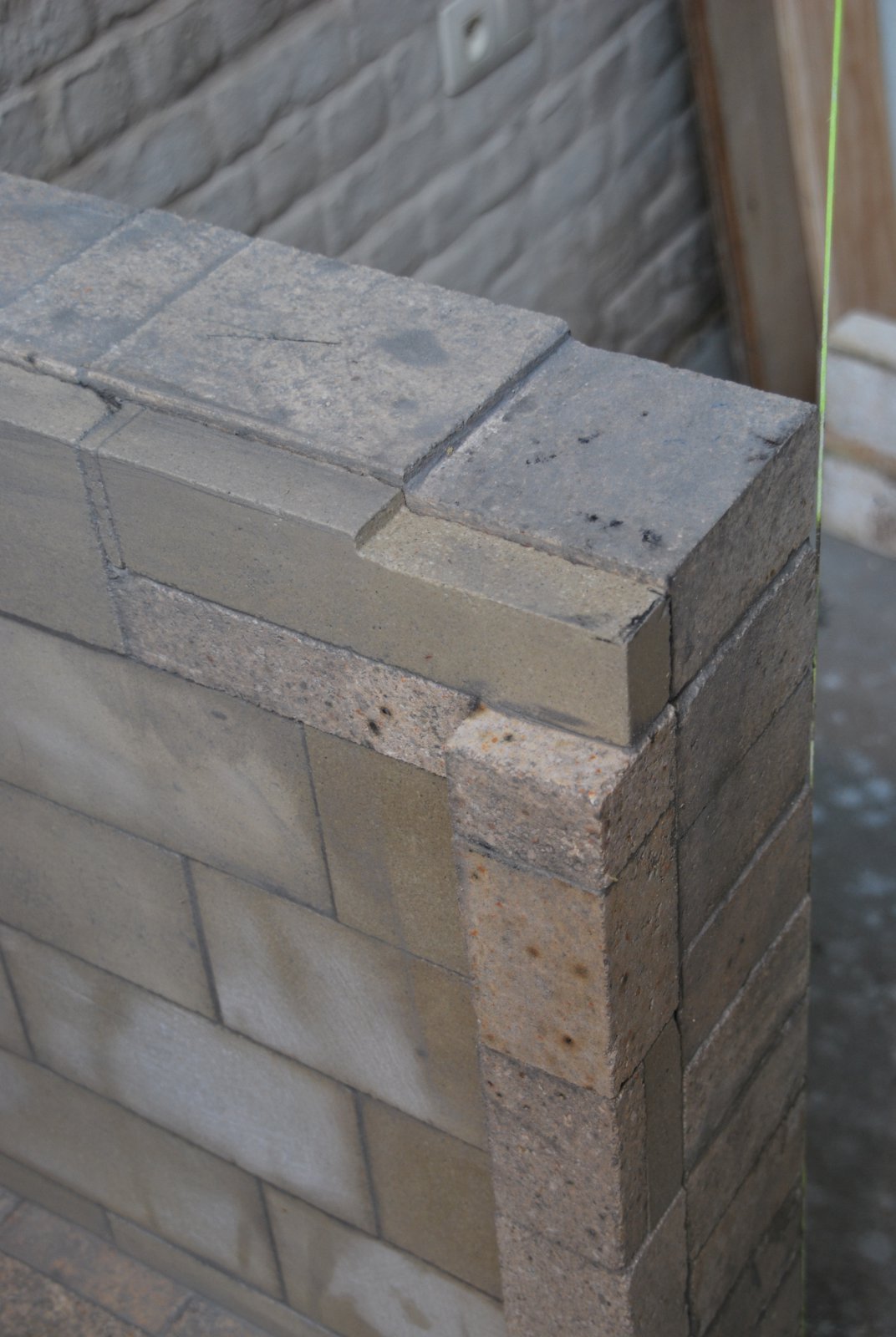
The skew cut edges are at the point where the 3.25 inch side channels meet the 5 inch side manifolds. The two skew cut bricks (one either side) which span the rear manifold are possibly the most difficult cuts in the core.
The skew cut edges are at the point where the 3.25 inch side channels meet the 5 inch side manifolds. The two skew cut bricks (one either side) which span the rear manifold are possibly the most difficult cuts in the core.
.jpg)
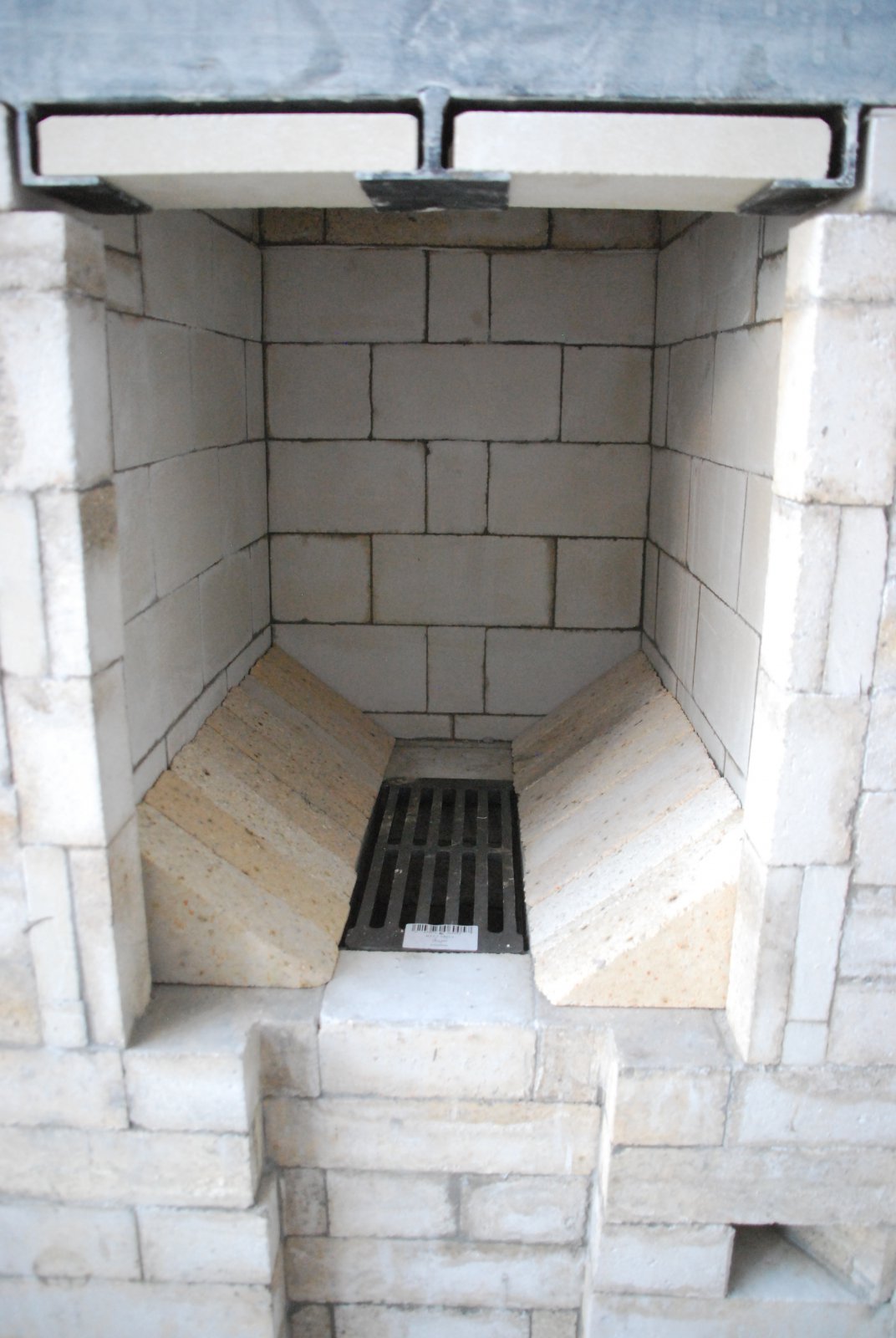
The fire box floor, with the grate in position. After the fourth course a third sheet of wool has been added to the two sheets already taped to the wall.
Note: More insulation would have been used had there been room to move the core foreward on the foundation slab.
Note: More insulation would have been used had there been room to move the core foreward on the foundation slab.
.jpg)
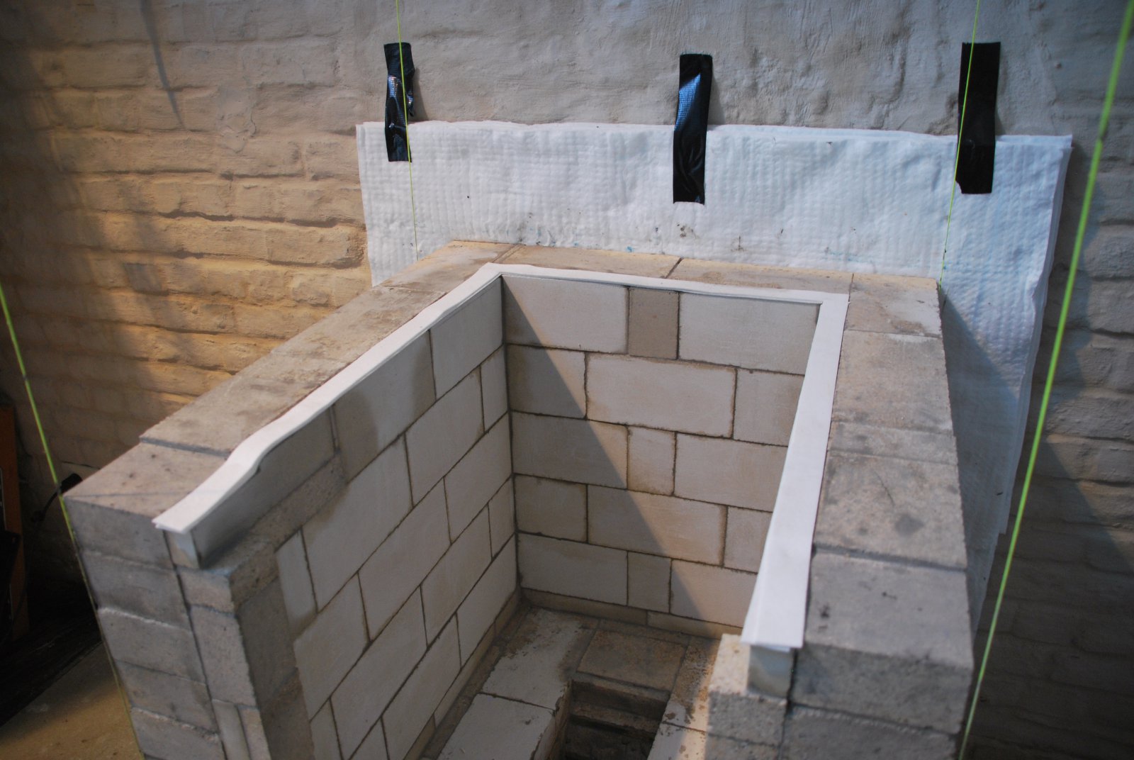
The fire box walls are built from brick layed flat. Here the brick have been sawn dow to 4.5 inches wide, from 5 inches in order to preserve cores overall dimensions. Two strips of folded ceramic felt are placed in the corners, as expansion gaskets, before laying up the liner.
.jpg)
A strip of aluminium foil acts as a bond break, and allows HTC to be pushed down behind the splits at this point in the row. The felt gaskets in the corners cause there to be a slight void between the splits in the middle of the row, and the firebox wall. Troweling HTC onto the back of the split in the middle of the row will bridge this space between the split and the fire box wall, offering resistance to any pieces of wood that should hit the back of the liner.
At the fire box opening the liner is turned inwards to shield the door jamb of the facing. Both full brick and splits are needed to do this. The fire box is 46cm wide, and the door only 41cm wide, which would leave about 2.5cm of facing each side of the opening exposed to direct radiation from the fire, were the liner not turned inwards. (See article: Shielding of 410 x 410 mm loading door opening)
.jpg)
The liner is cut down to about 4mm lower than the fire box walls, to accommodate the felt expansion gasket.
.jpg)
Two sheets of 3mm ceramic felt are used to gasket the upper surfaces of the liner. This prevents the liner, which will expand sooner than the fire box walls behind it, lifting up the core above.
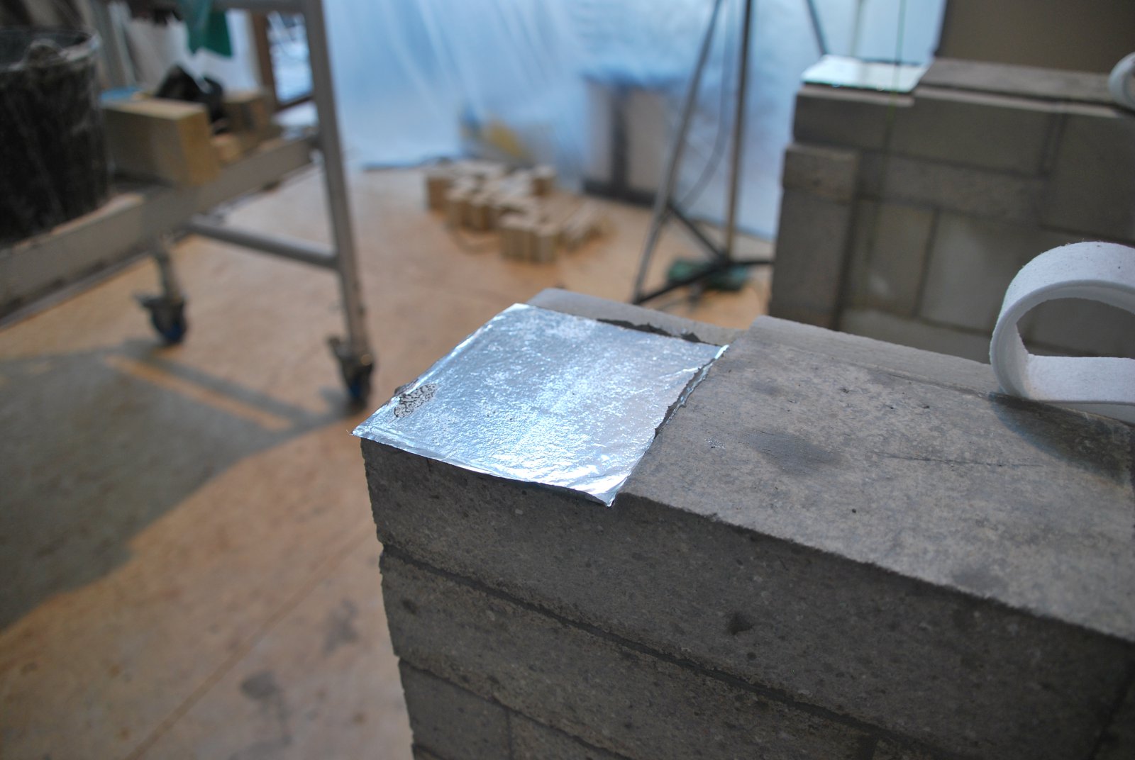
The cut outs in the fire box wall for the lintel. In order to create an even bed for the lintel to rest, liquid HTC is spread upon the upper surface of the brick, then covered with a sheet of aluminium foil, the lintel placed on top and slid from side to side rapidly while exerting downward pressure. This evens out the surface of the ground brick and provides perfect contact with the lower surface of the bar. The foil acts as a bond brake, allowing the lintel to slide without dragging the firebox walls.
The first course above the lintel. Here the NF2 format lays out well, though the extra length and width, cause hand and arm ache.
The second, and start of the third course above the lintel.
The third course above the lintel. Each course corbels approximately 3.5 inches.
The fourth course above the lintel.
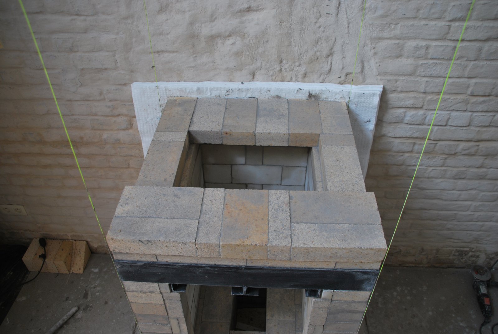
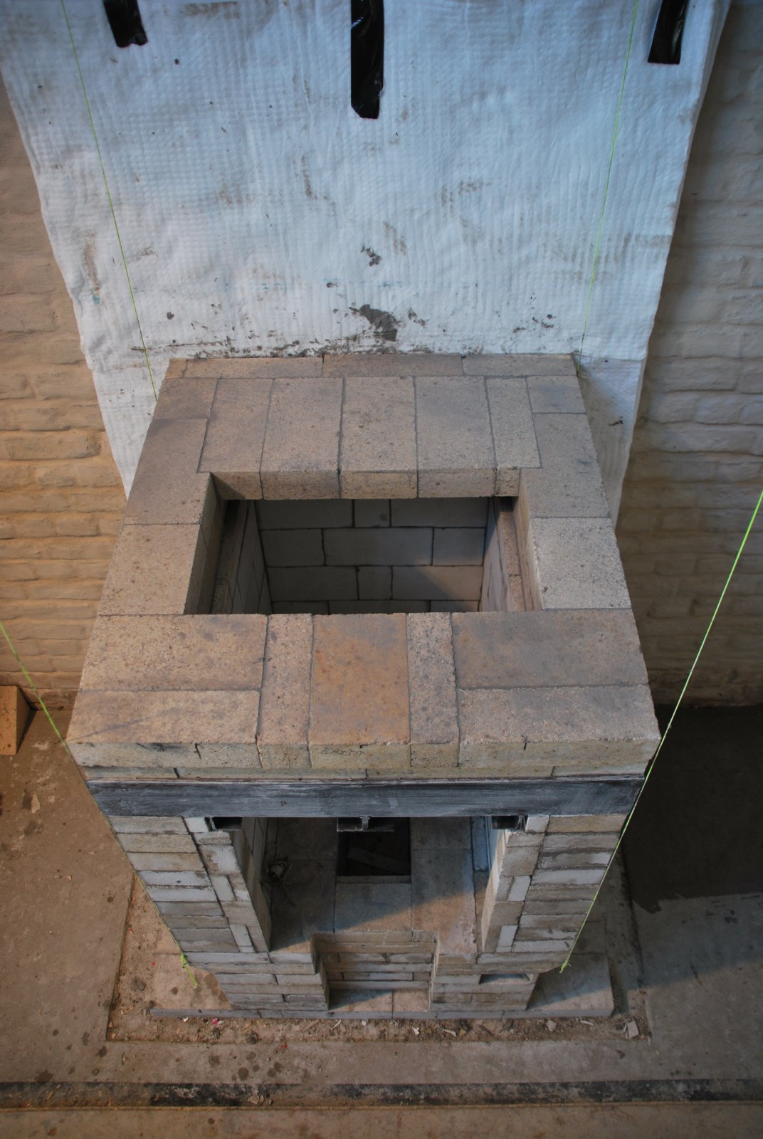
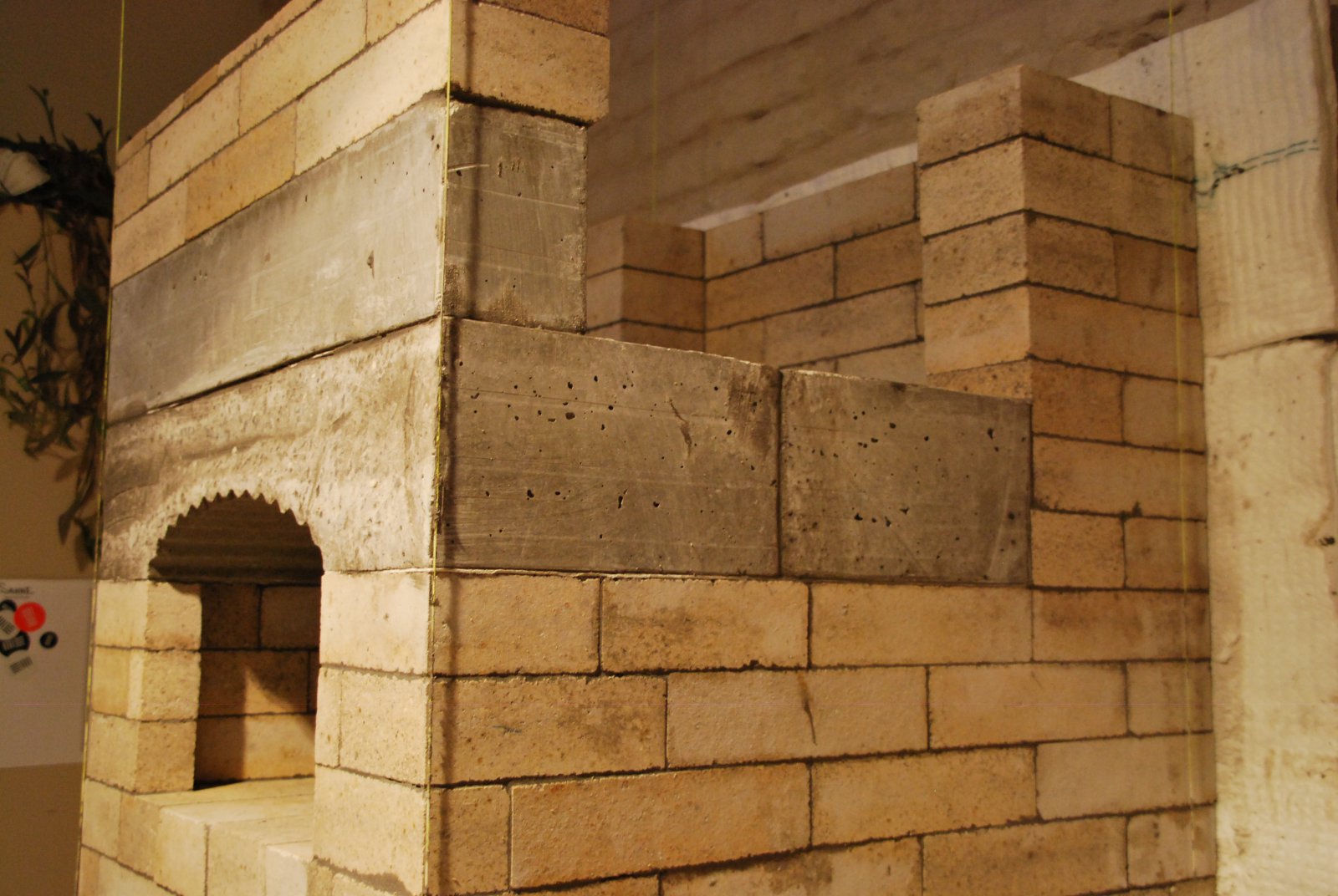
The sixth course above the lintel. This course will be the ovens hearth.
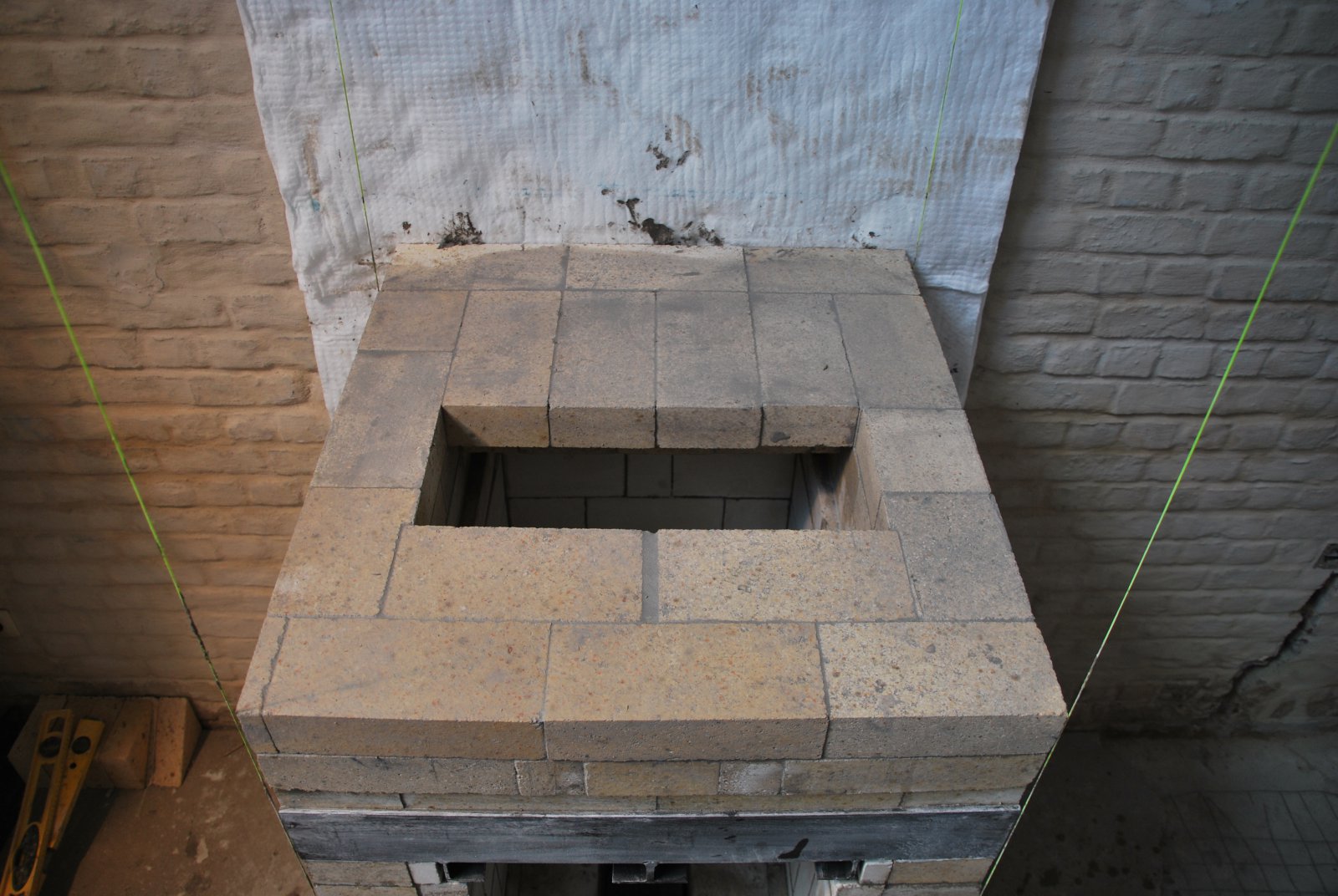
The three courses of the ovens walls.
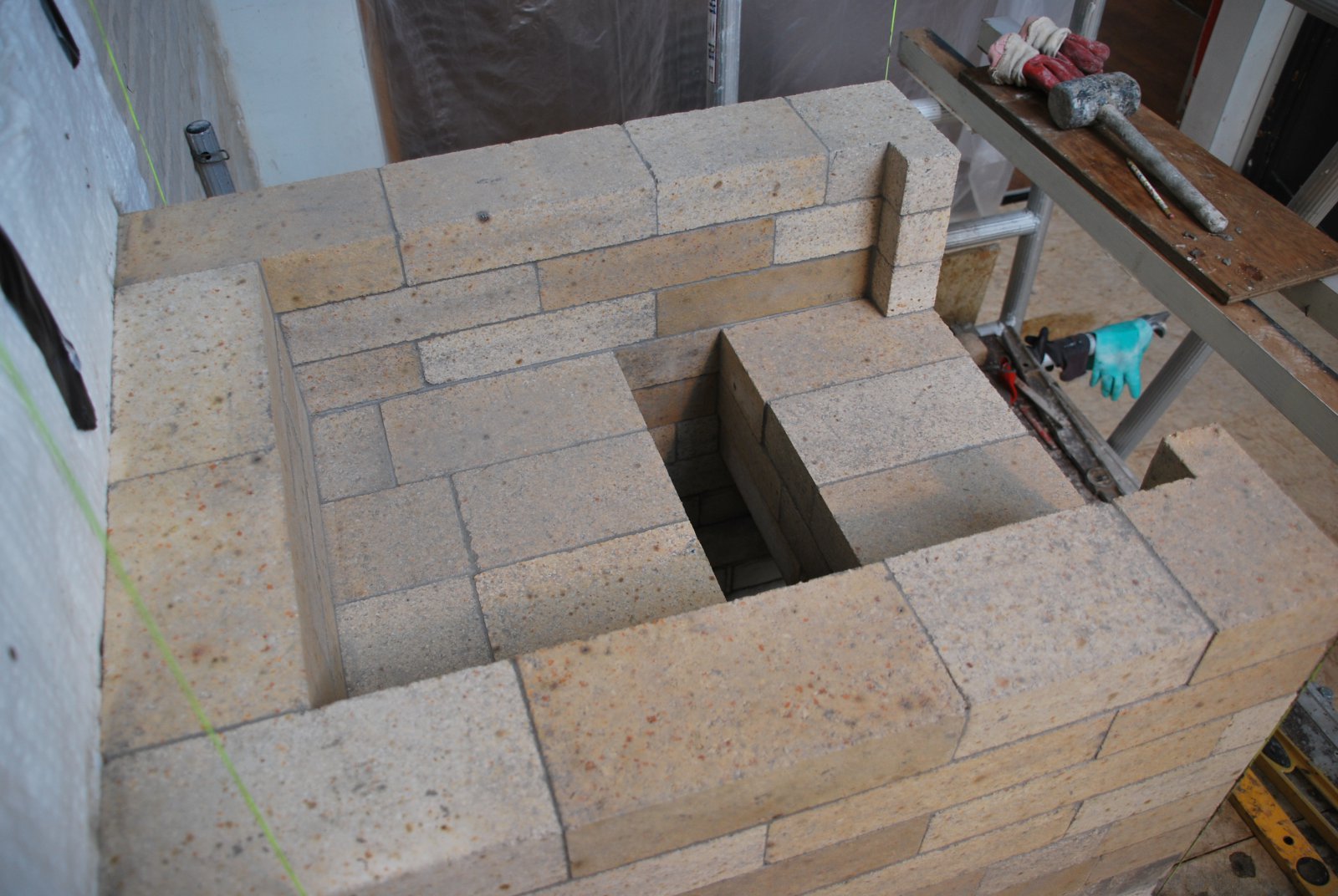
The ovens walls are turned in at the opening to protect the facing around the door.
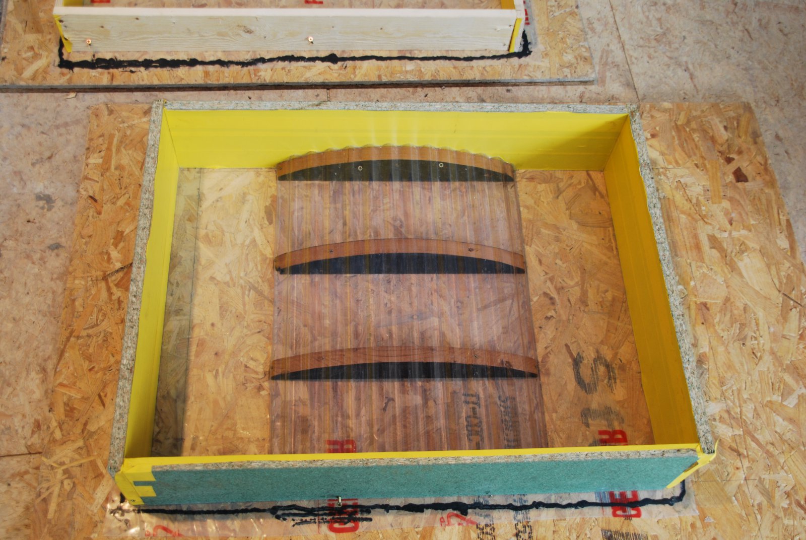
The oven slab will be cast in refractory concrete. The mould is lined with water proof tape, and set up on a sheet of plastic, that has been glued to the wood below. All the inside corners, and the places at which the corrugated plastic meets the sides and bottom of the mould, are sealed with a bead of silicon.
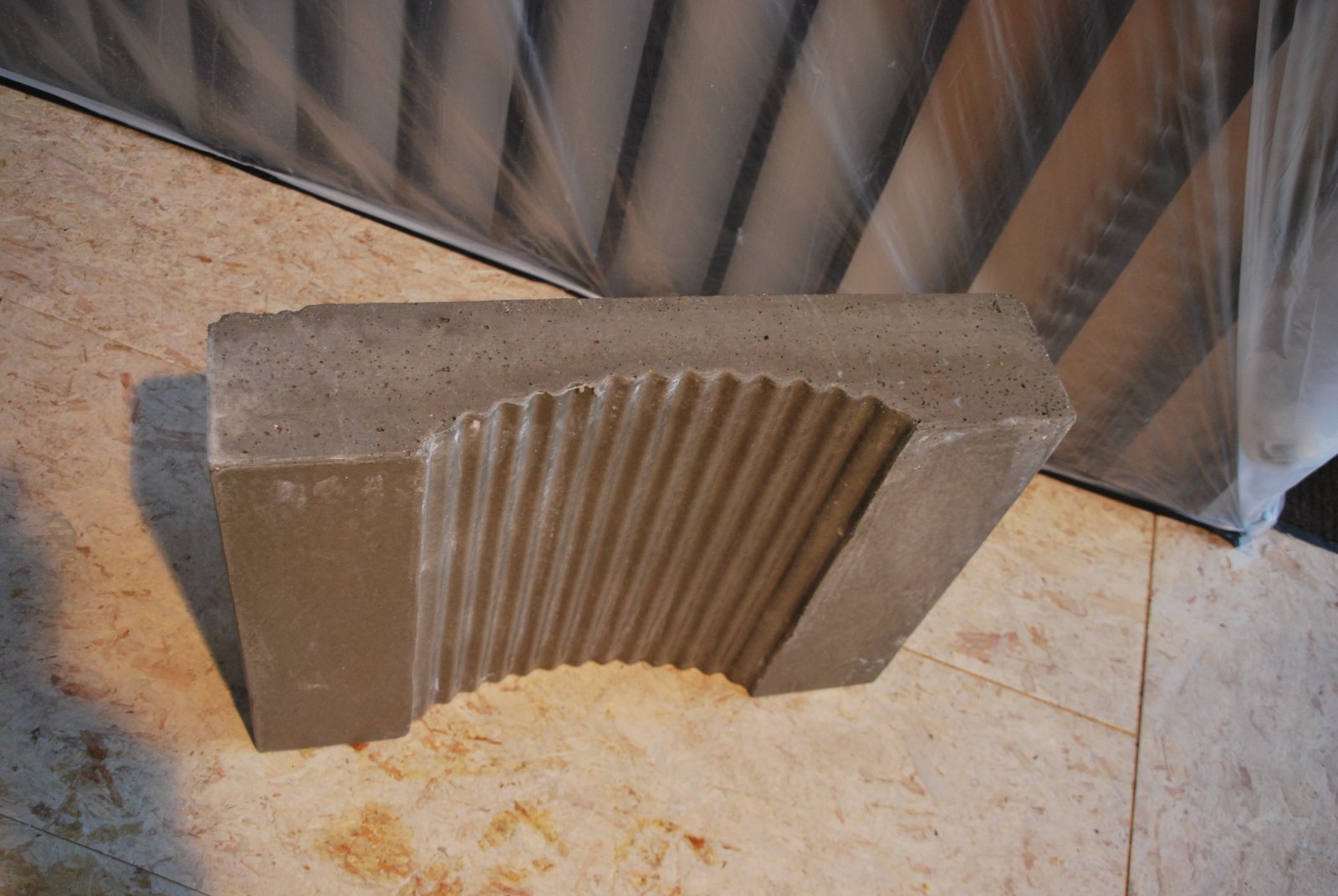
The deformed oven slab. Placing a piece of this weight with the scaffolding and manpower available would be risky.
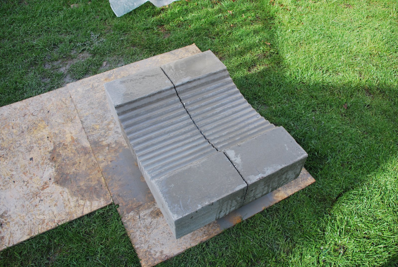
The piece was taken outside and sawn in half with a 7 inch grinder.
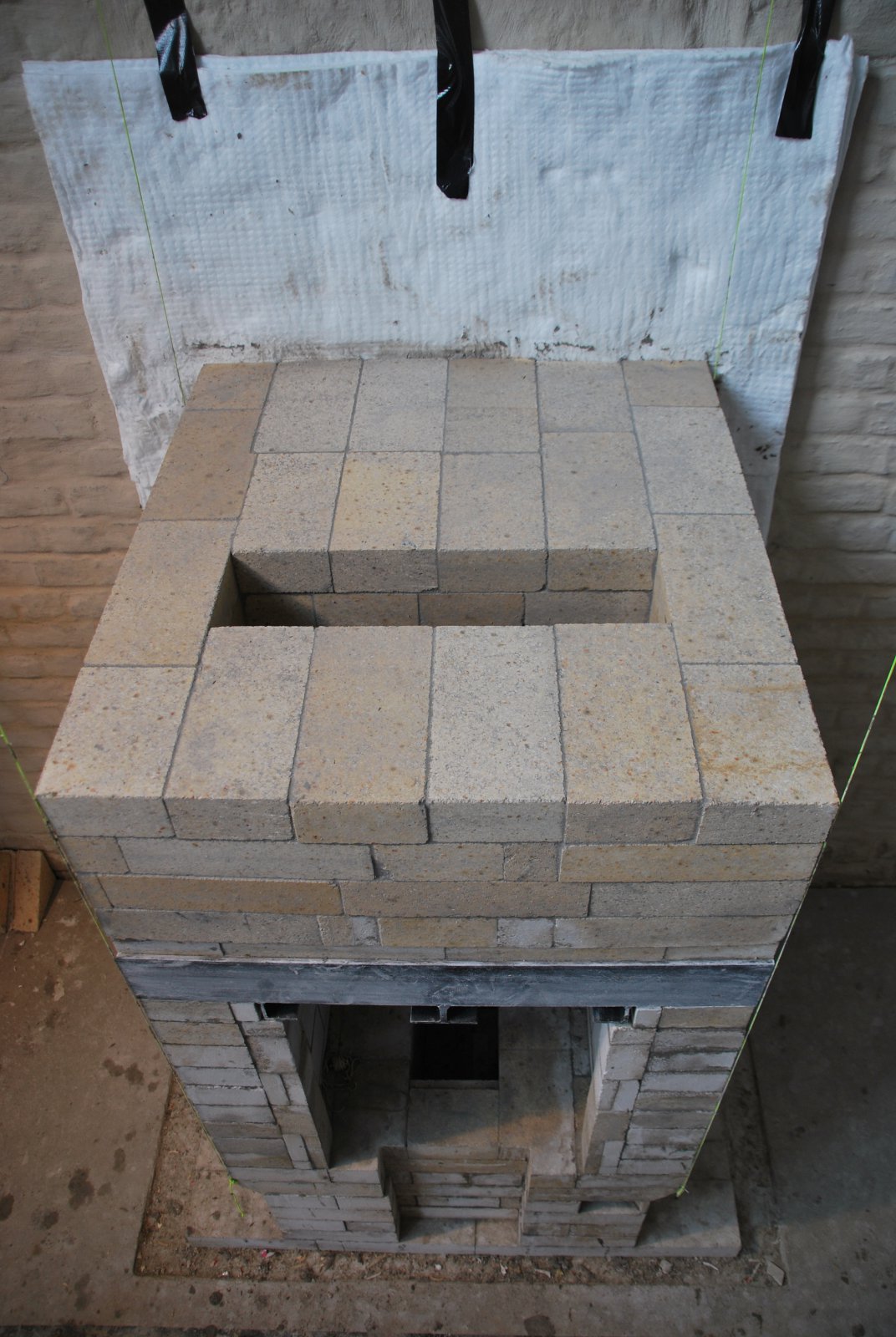
The two halves of the original piece are layed dry onto a gasket of ceramic felt. The two straight ends, ie not the saw cut surfaces, are joined, and parged along the outer surface of the joint. There is also a felt gasket between the oven slab and the side walls of the exit throat, making both slabs free floating. The load relieving lintel. is also gasketed with felt, and only contacts the oven slab below for 5 inches at each end.
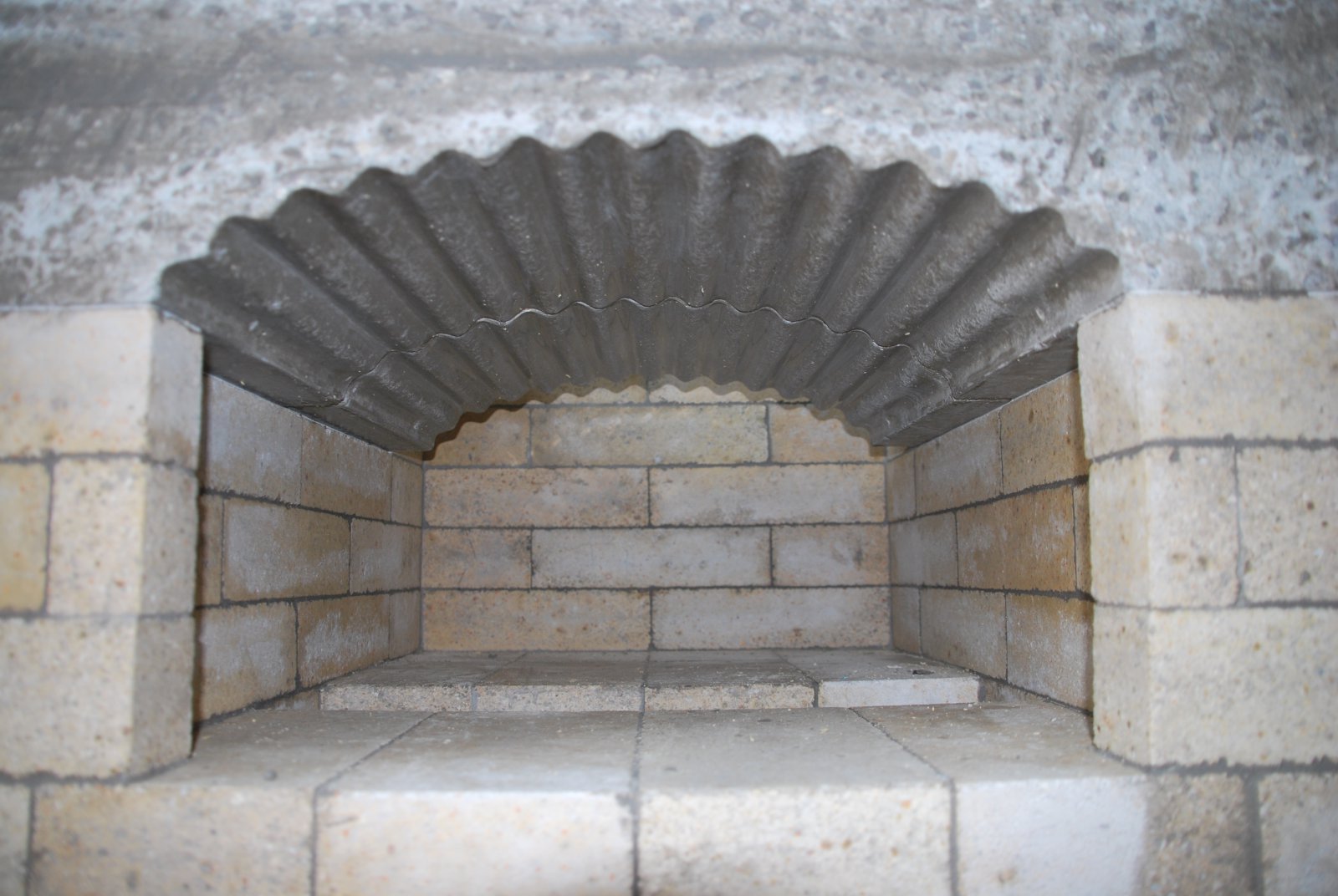
The curve of the oven slab, follows exactly the curve of the oven door. Along with the hight of the oven walls this will ensure that the facing around the opening is completely shielded. (Except the surface of the door jambs)
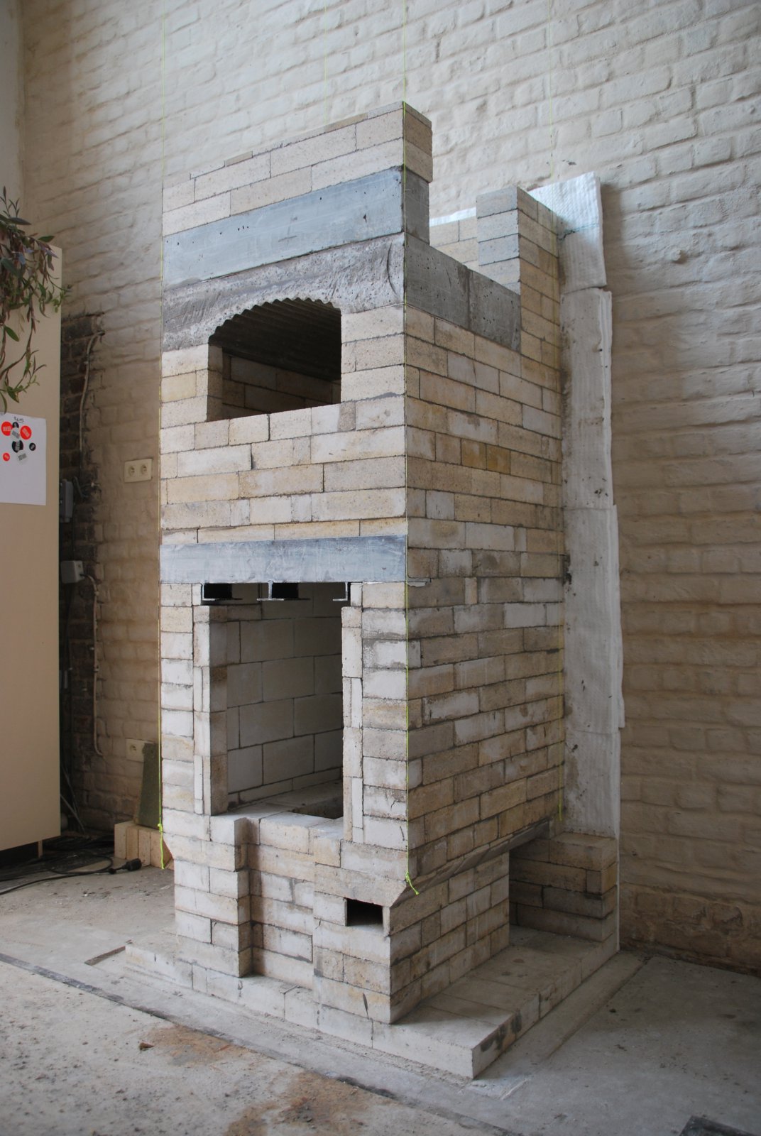
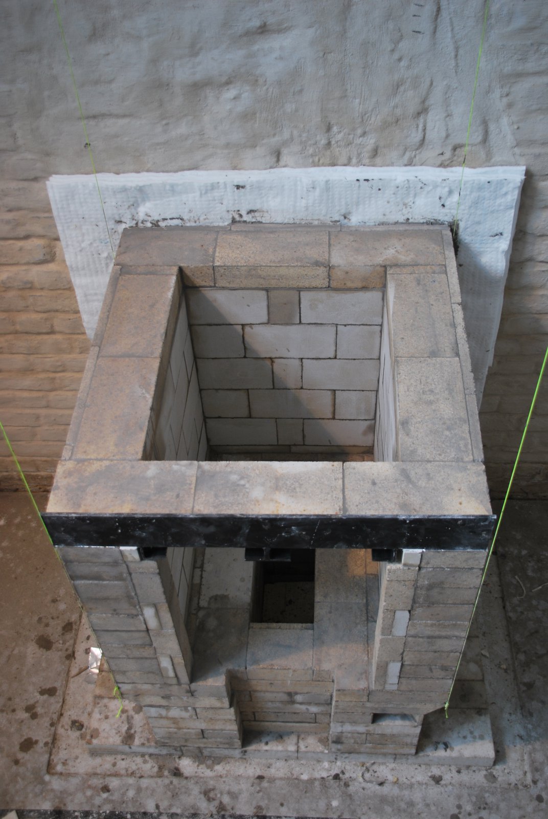
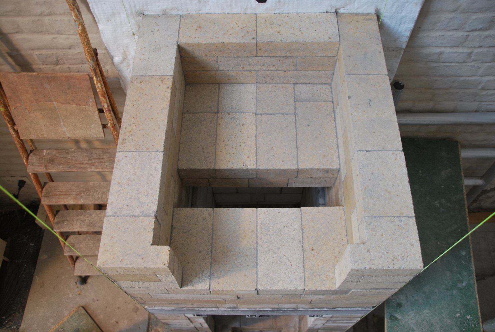
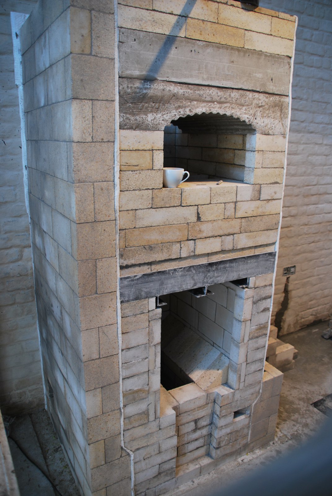
The completed core.
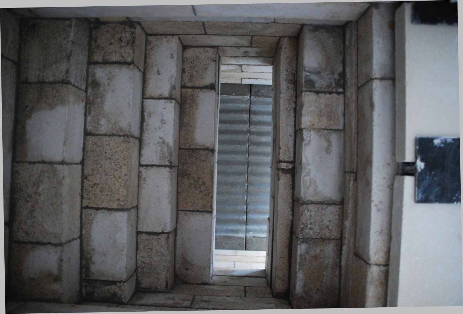
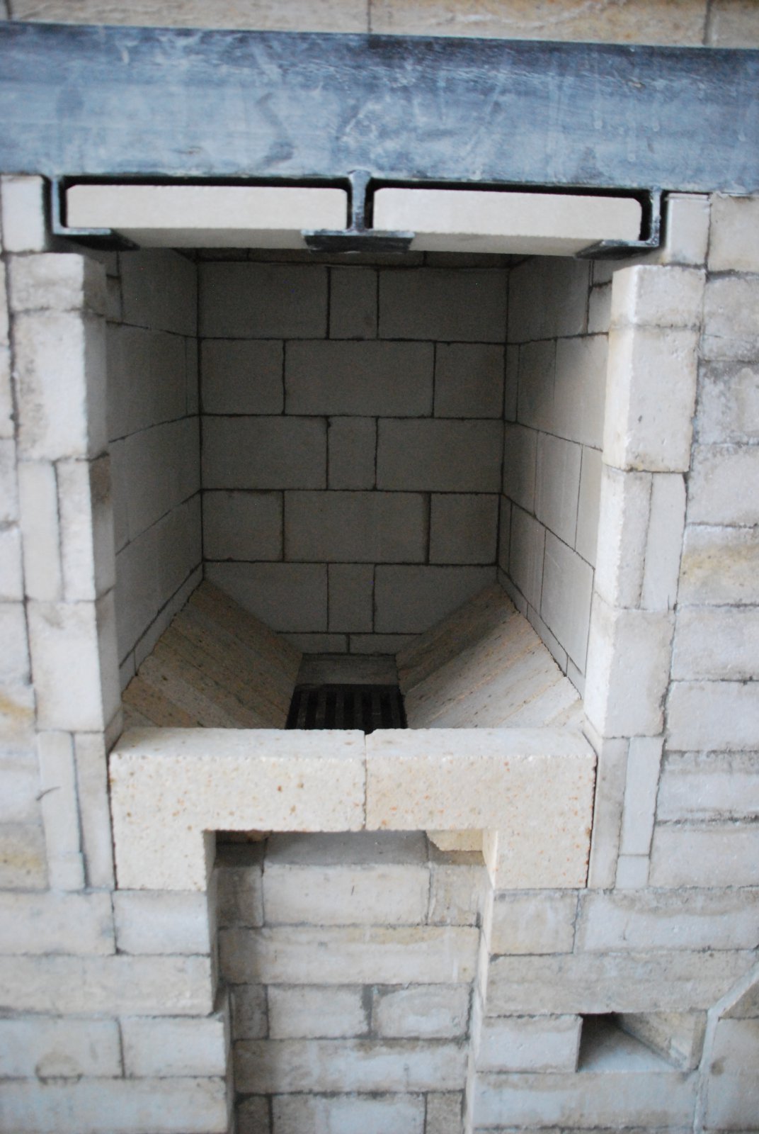
View of the fire box ceiling, and the oven slabs, through the throat.
The two caping slabs which were cast at the same time as the oven slabs are left outside beneath wet sheets.
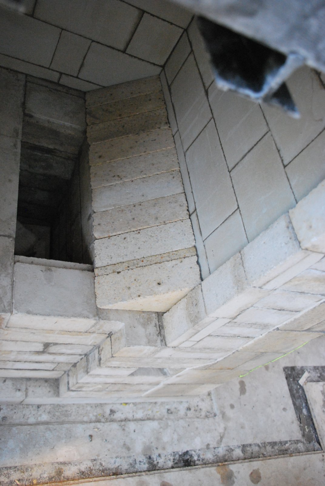
The start of the left side channel.
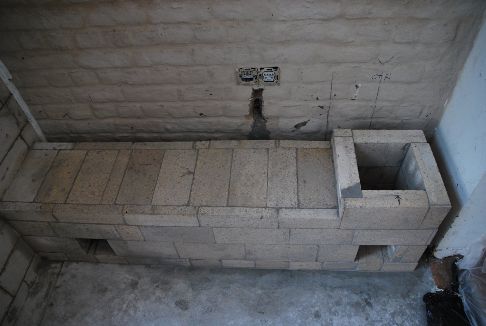
The completed left side channel.
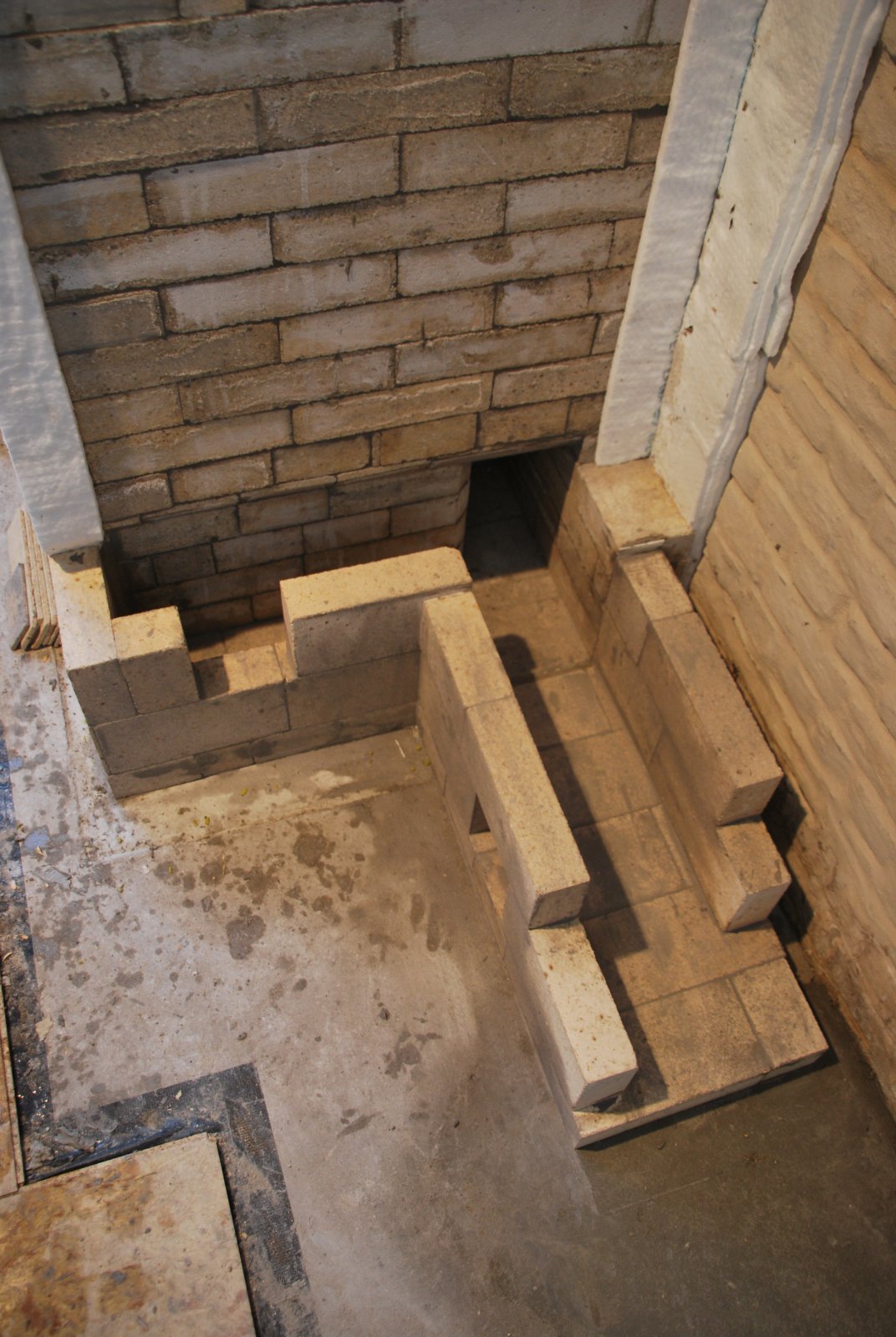
The start of the transmission tunnel at the right manifold.
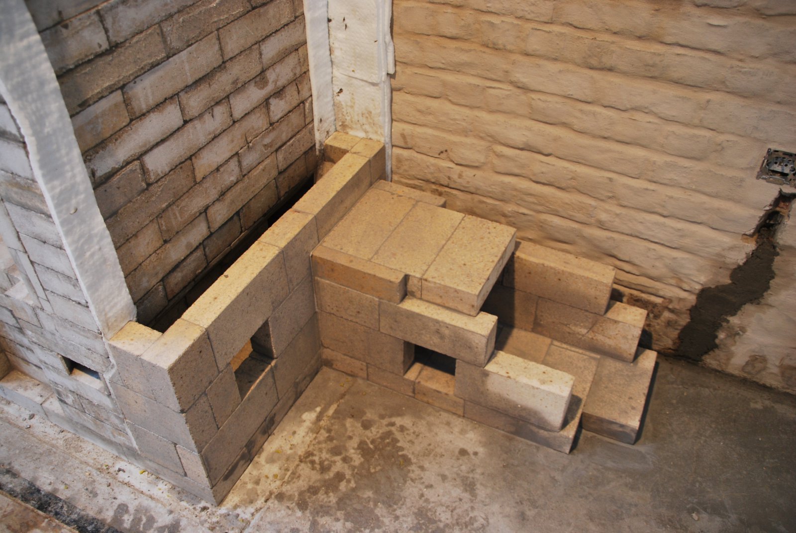
The tunnel is butt joined and not tied into the channel wall.
A plastic coated electrical cable, which ran beneath the bench and up the wall to an outlet socket, was removed. The cable will be re-routed down the wall i.e. not lying below or behind the tunnel.
A plastic coated electrical cable, which ran beneath the bench and up the wall to an outlet socket, was removed. The cable will be re-routed down the wall i.e. not lying below or behind the tunnel.
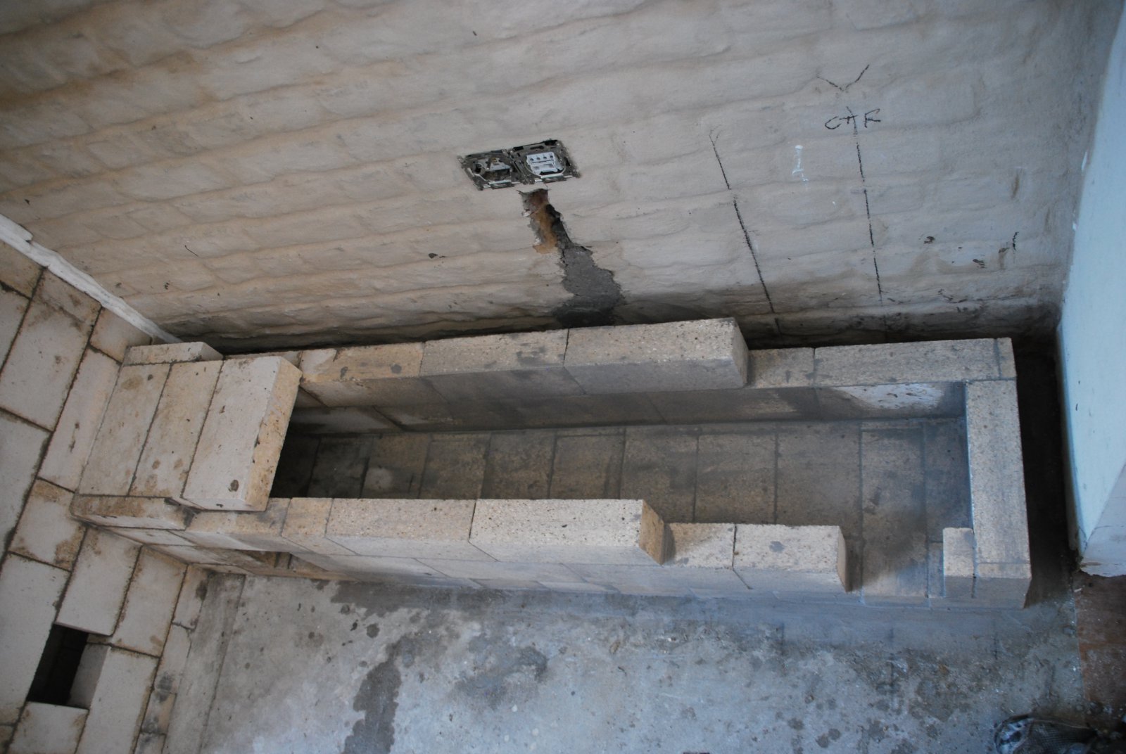
The second course of shiners have been cut down from 5 to 4 inches in order to keep the bench top low.
The inside dimensions. of the tunnel are 9 x 8 inches, with the base of the chimney at 8 x 8 inches.
The skew cut shiners for the fire box floor are layed dry. Note the free space left for expansion at the end of the row.
Splits are placed in the slots below the angle bar lintel.
Two brick are cut as over air deflectors. These too are layed dry, and will be pushed out slightly, to contact the back of the facing.
View inside the upper chamber. Before the capping slabs are lifted into position, a gasket of wool will be layed on the upper surfaces of the core and side channel walls. The throat is 5 inches wide, and the side channels 3.25 wide.
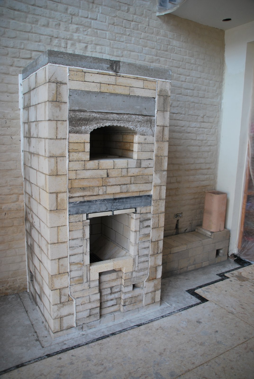
The finished core. The brick facing will be layed by the home owner.
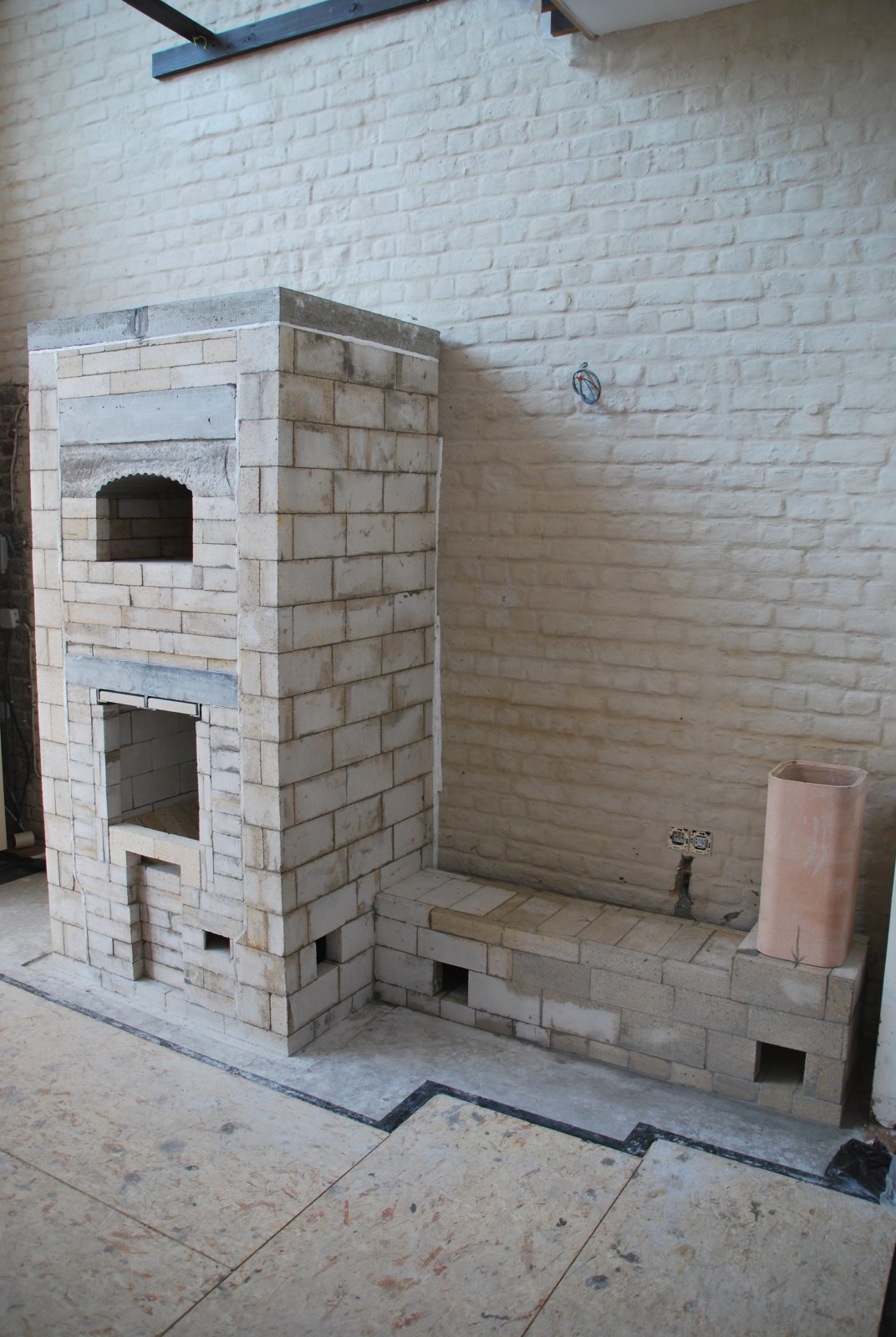
The first 6 feet of chimney will be in refractory clay tile faced in brick. This will allow the installation of a guillotine damper, and provide thermal retention at the bottom of the chimney. The rest of the flue to the roof will be in 8 inch round insulated steel chimney.
Marcus Flynn
2018
