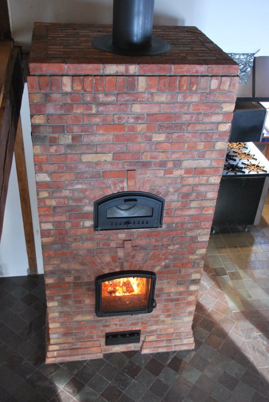
Top Exit. Construction Sequence 2018
The following images and text document the construction of a custom built Swedish style masonry heater in Quebec. Swedish heaters are also known as top exit, and five run stoves. Or in Sweden generally, as kakelugn.
The difference between the kakelugn and the Finish takka is the orientation of the smoke path after the upper chamber. Combustion efficiency will be equal.
The contra flow takka has two side channels down which gases descend, from the upper chamber, into a chimney connection at the base of the heater. The chimney has to be on either side, or at the back of the heater . This gives a rectangular footprint, with a smaller rectangle, or square, representing the chimney, to one side or the rear.
The kakelugn has each of its two side channels divided, and linked at the bottom. Gases travel down the front portions of the channels, and then back up the rear portions of the same channels, exiting to the chimney on top of the stove. This gives a simple rectangular footprint. The stove cannot support the weight of a masonry chimney, and so needs to be served by a prefabricated chimney.
Both the takka and kakelugn were developed in Sweden, though Finland widely uses the takka and Sweden the kakelugn to the point that they are known to us as Finnish and Swedish stoves respectively.
In this situation, a pre-existing footing in a finished home left no room for a contra flow stove with its chimney to one side or the rear.
The project was undertaken with technical assistance from Albert Barden and Norbert Senf.
The general design is based upon the stove built at the MHA 2011 AGM
See also the article: Top Exit: Thermal Images
MATERIALS
Stretchers:
Alsey Jet DP High Duty and Alsey Smithfield Medium Duty. NB medium duty.
Splits:
CMC39 Medium Duty.
HTC:
Mount Savage Super High Mull.
Paper:
Vesuvius ceramic felt ⅛ "
Wool:
Superwool 607HT Half inch.
Castable:
Mount Savage Heatcrete 24 esc.
Metalwork:
Pascal Duhamel of AD Bourgea.
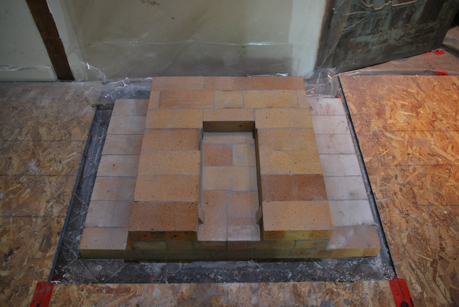
Due to the house having no basement, the ashes will be removed via the ash box door, which also acts as a primary air intake door.
Note the two small cuneiform pieces of brick laid at each side of the opening. These will ensure that the tapered Pisla ash draw, will fit tightly into the opening, and not allow primary over air to be diverted beneath the grate as under air.
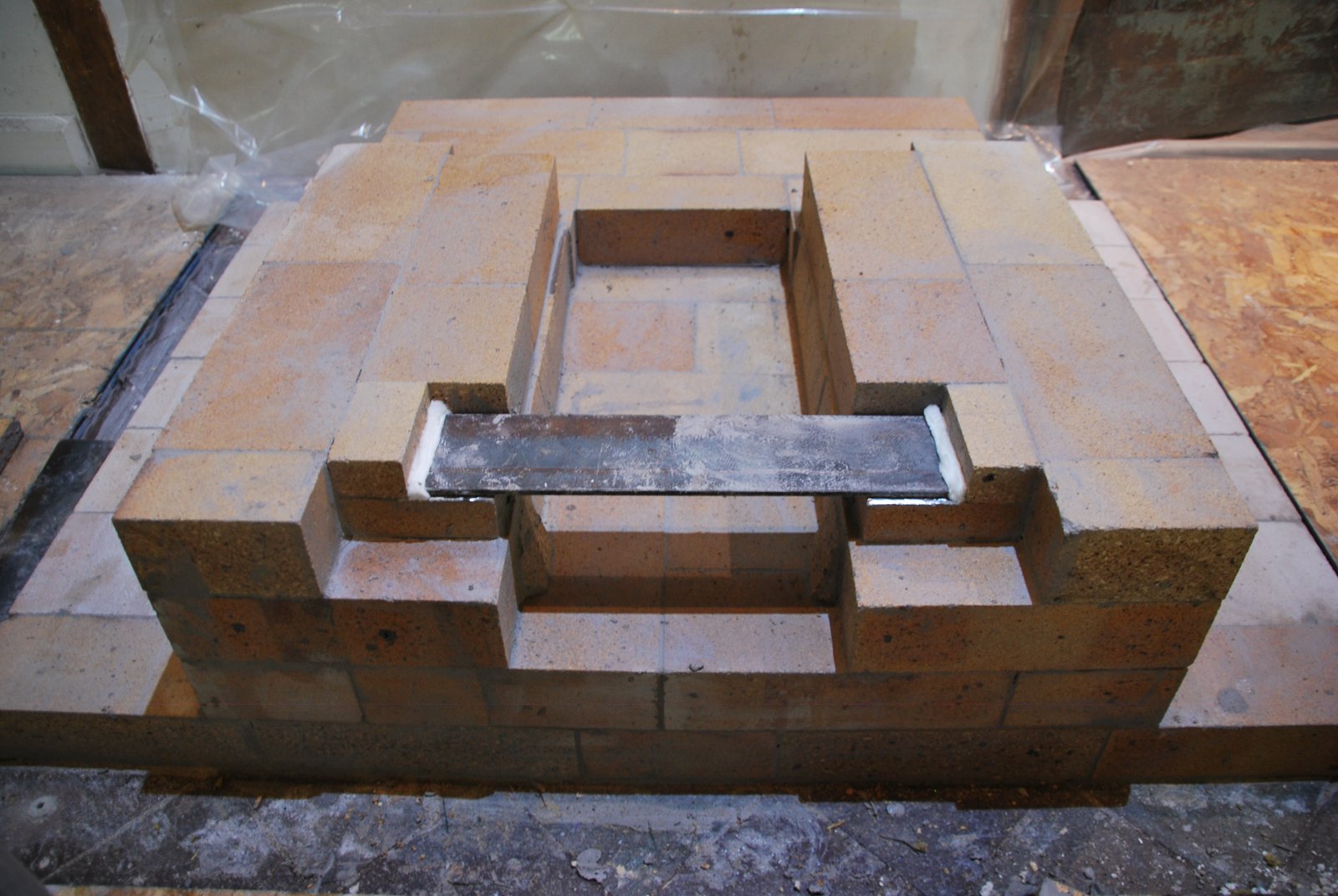
The ash box door opening will be bridged by a quarter inch thick flat bar lintel. Aluminium foil placed on loose HTC provides a uniform contact with the lintel and brick below, and also act as a slip joint.
The flat bar lintel has both ends gasketed with wool.
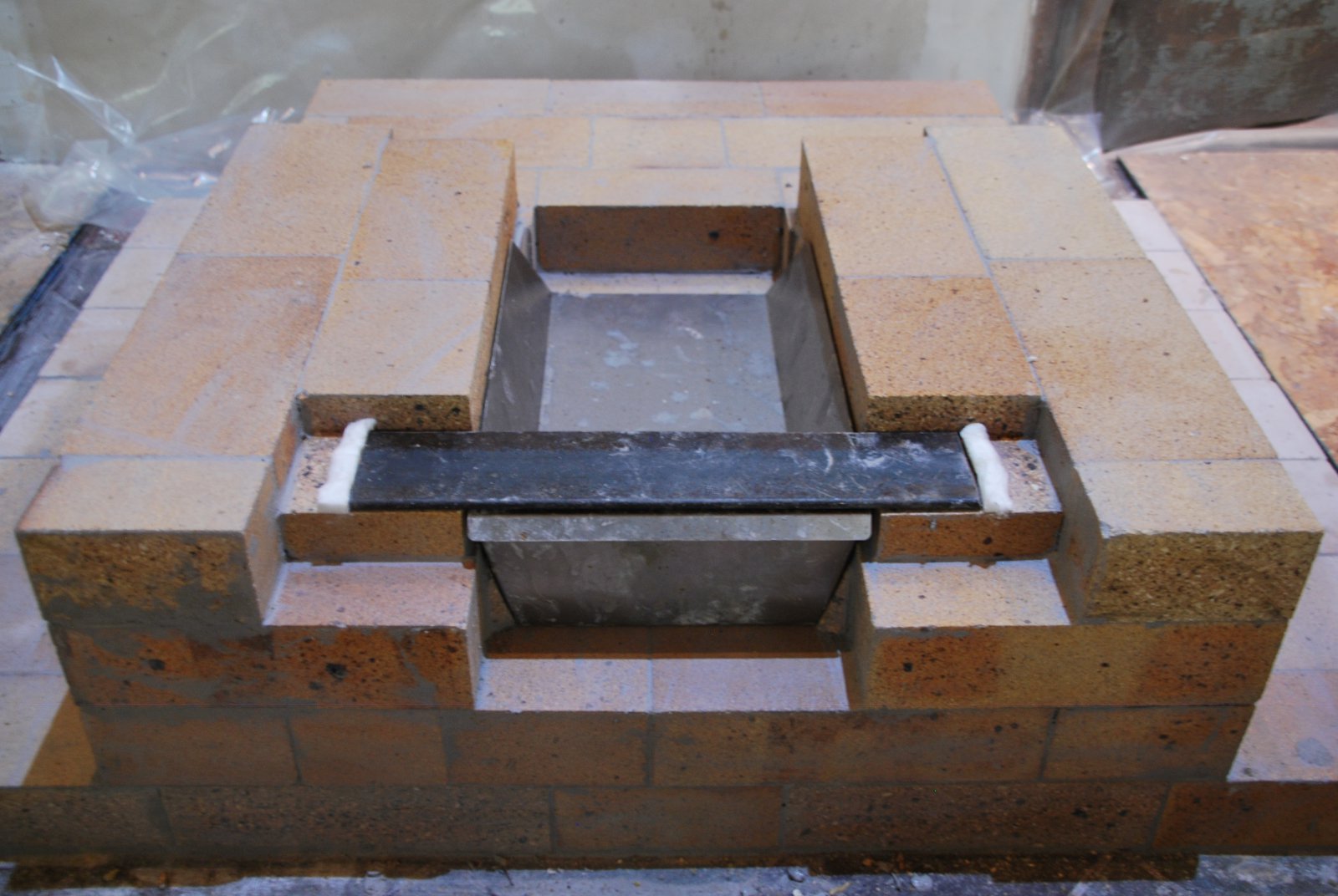
The Pisla ash draw. The draw fits as tightly as possible below the lintel, its handle not protruding into the primary air channel.
The lintel is bridged up to the height of the 4th course.
Course 5. Up to this point medium duty Indian brick have been laid as they are more economical than Alseys Smithfield.
The skew cut course below the firebox floor is laid in Smithfield medium duty brick.
The firebox floor is laid in Alseys Jet DP high duty brick.
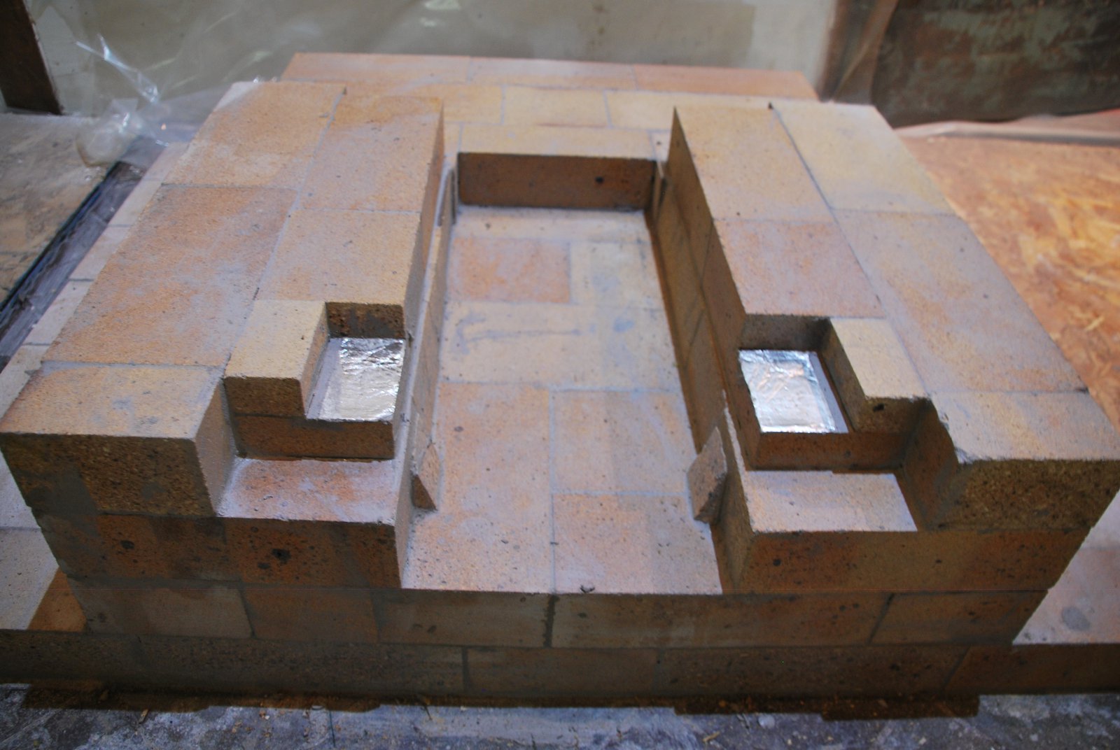
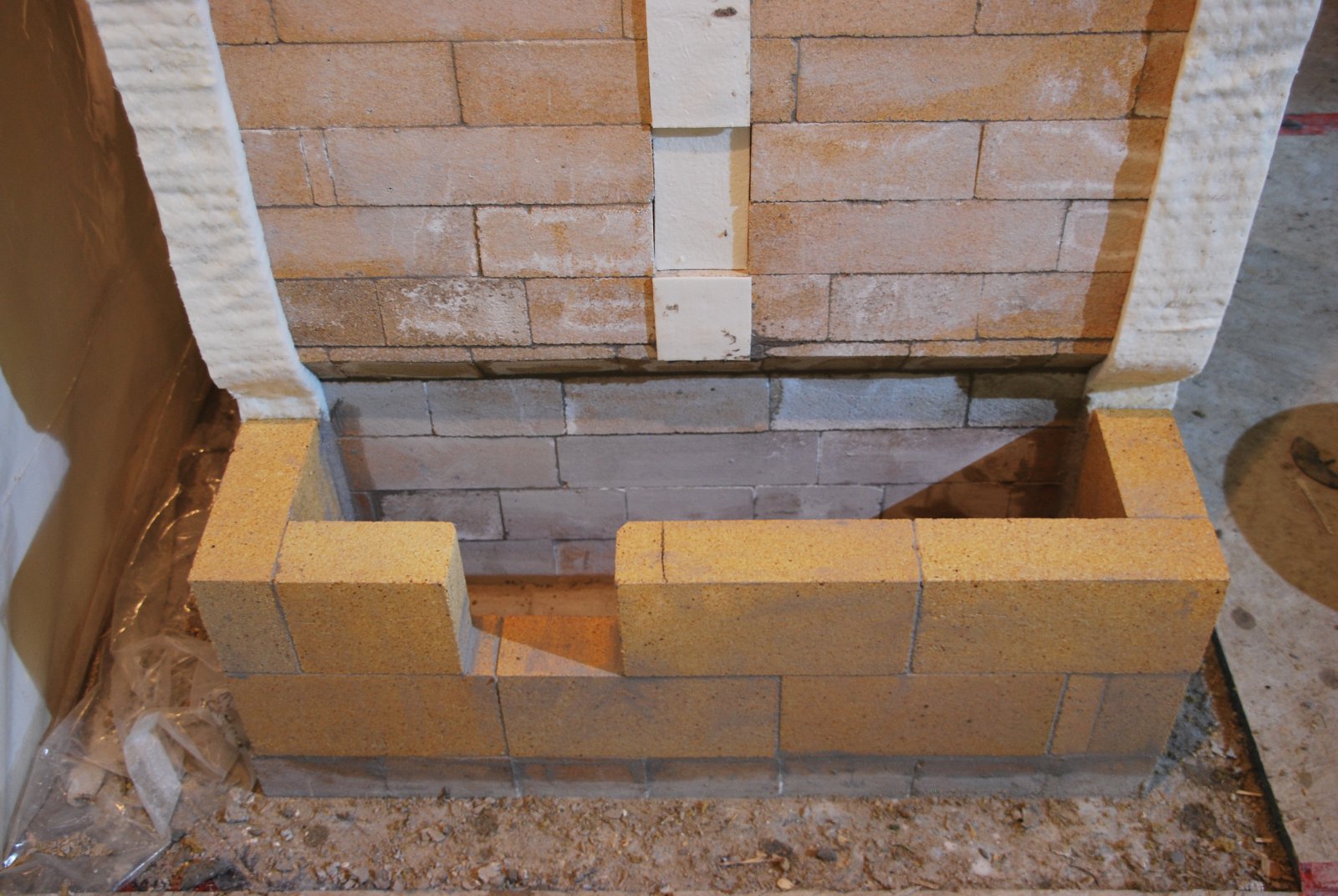
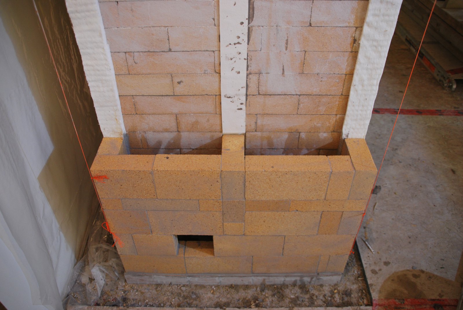
The firebox walls have a cut out in each side to support the brick that devide each channel into two.
The firebox is laid in Jet DP.
Note the cut outs to accept the lintel that will bridge the opening.
The back corners of the firebox are gasketed with paper before laying the liner.
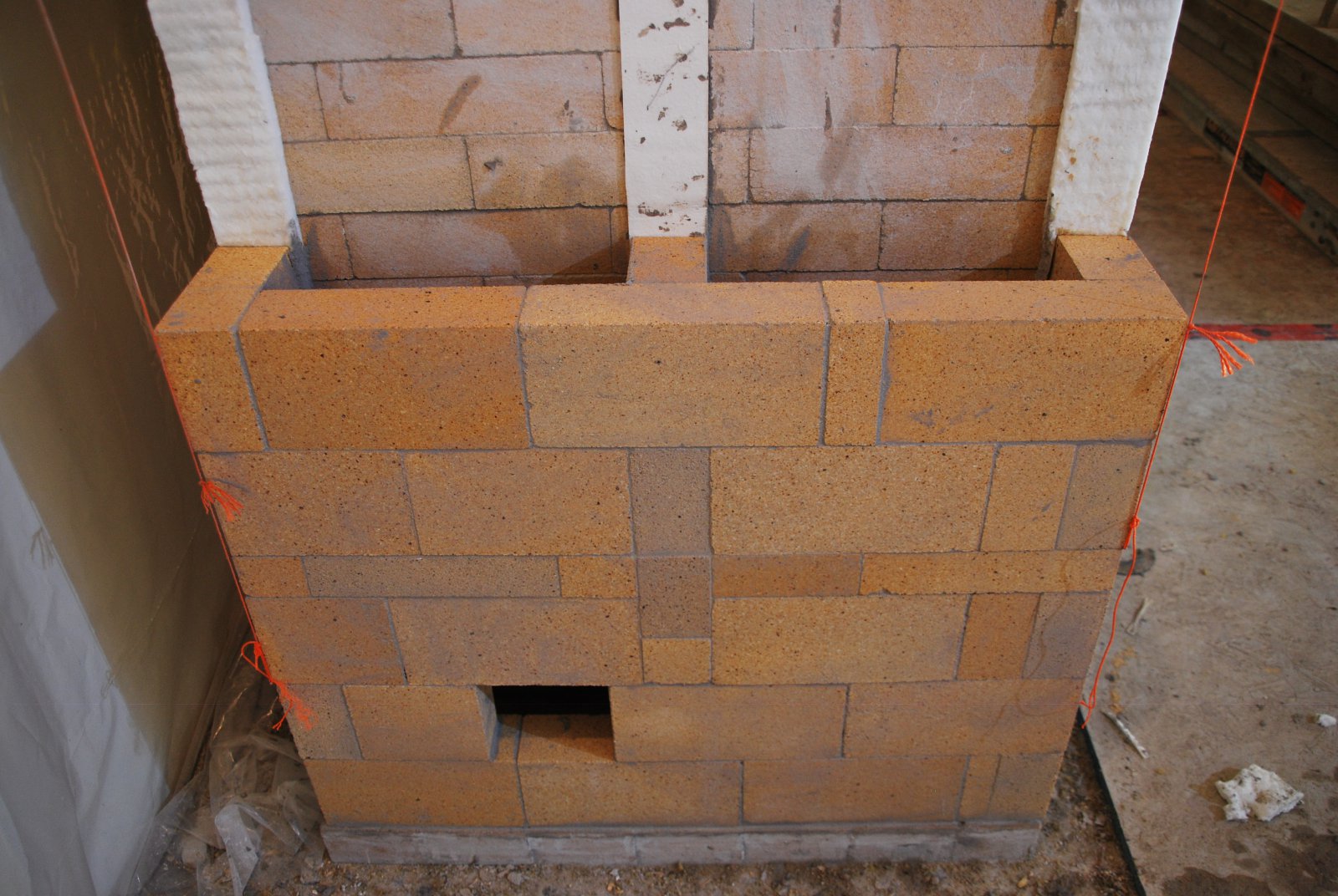
The liner of splits is laid ⅛ of an inch below the top of the firebox wall.
A single layer of paper is laid onto the upper surfaces of the liner enabling the liner to rise slightly without effecting the work above. The liner will become hotter, faster than the wall behind it and so expand sooner.
Aluminium foil is laid on top of loose HTC and the lintel quickly pressed down upon it and slid from side to side before the HTC has time to thicken and jam. This provides perfect contact between the lintel and the brick, and acts as a slip joint.
The first course of brick above the firebox lintel.
Fifth Course. All these corbelled courses are in Jet DP. The following work is in Smithfield.
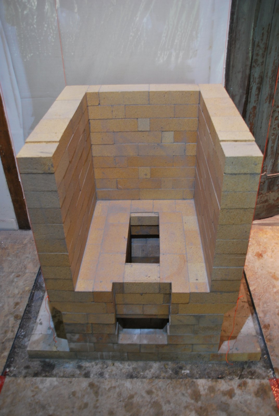
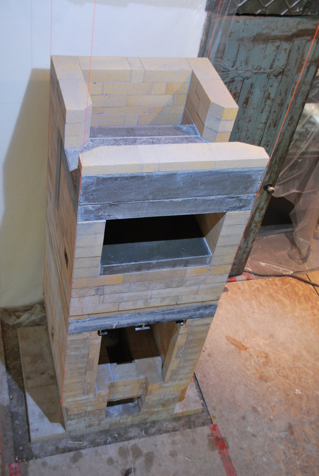
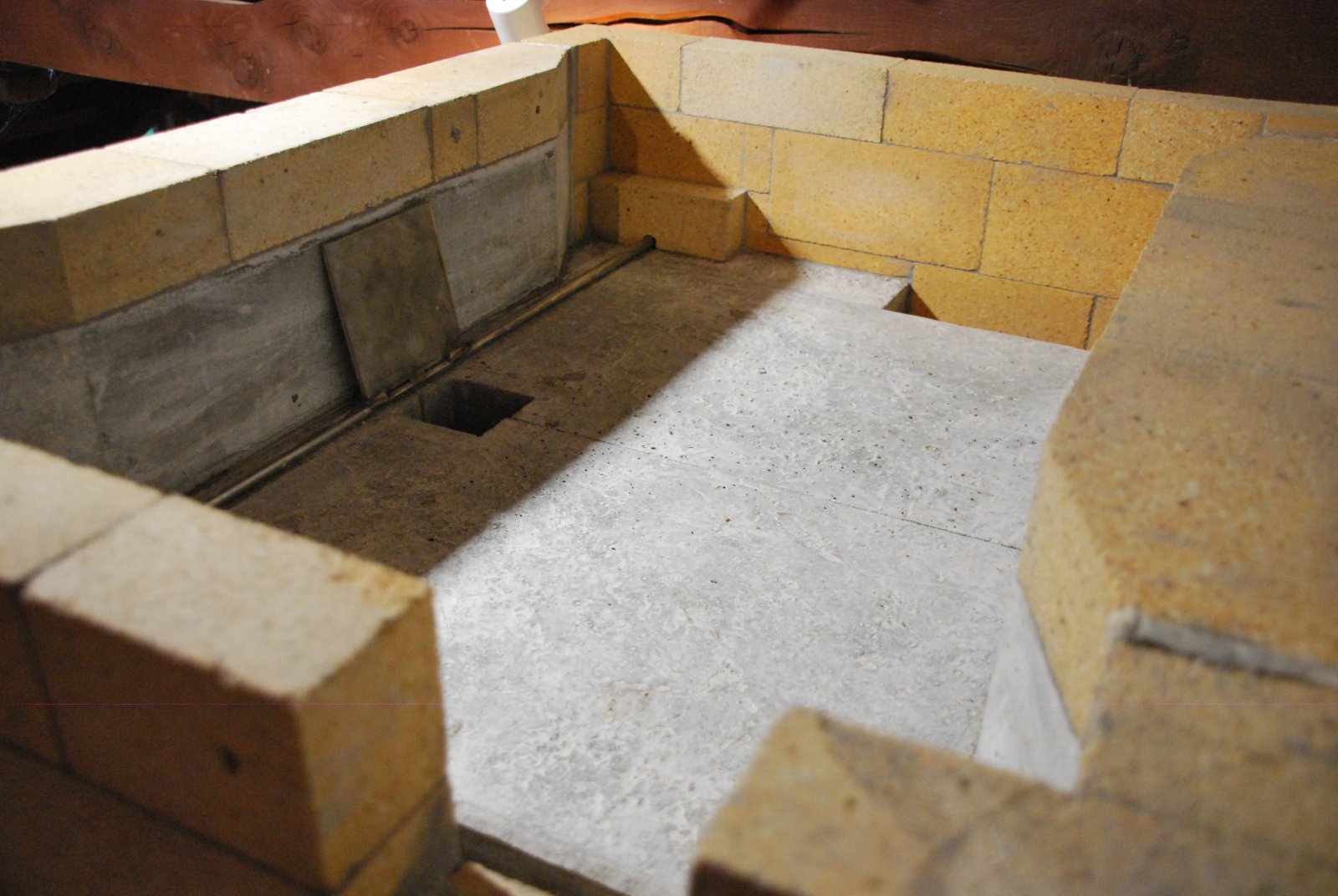
The under hearth channel is formed by the sixth course. It is upon this course that the oven hearth slab will rest. Details of the construction of this type of white oven oven can be seen at White Upper Chamber Bakeoven Images 2005.
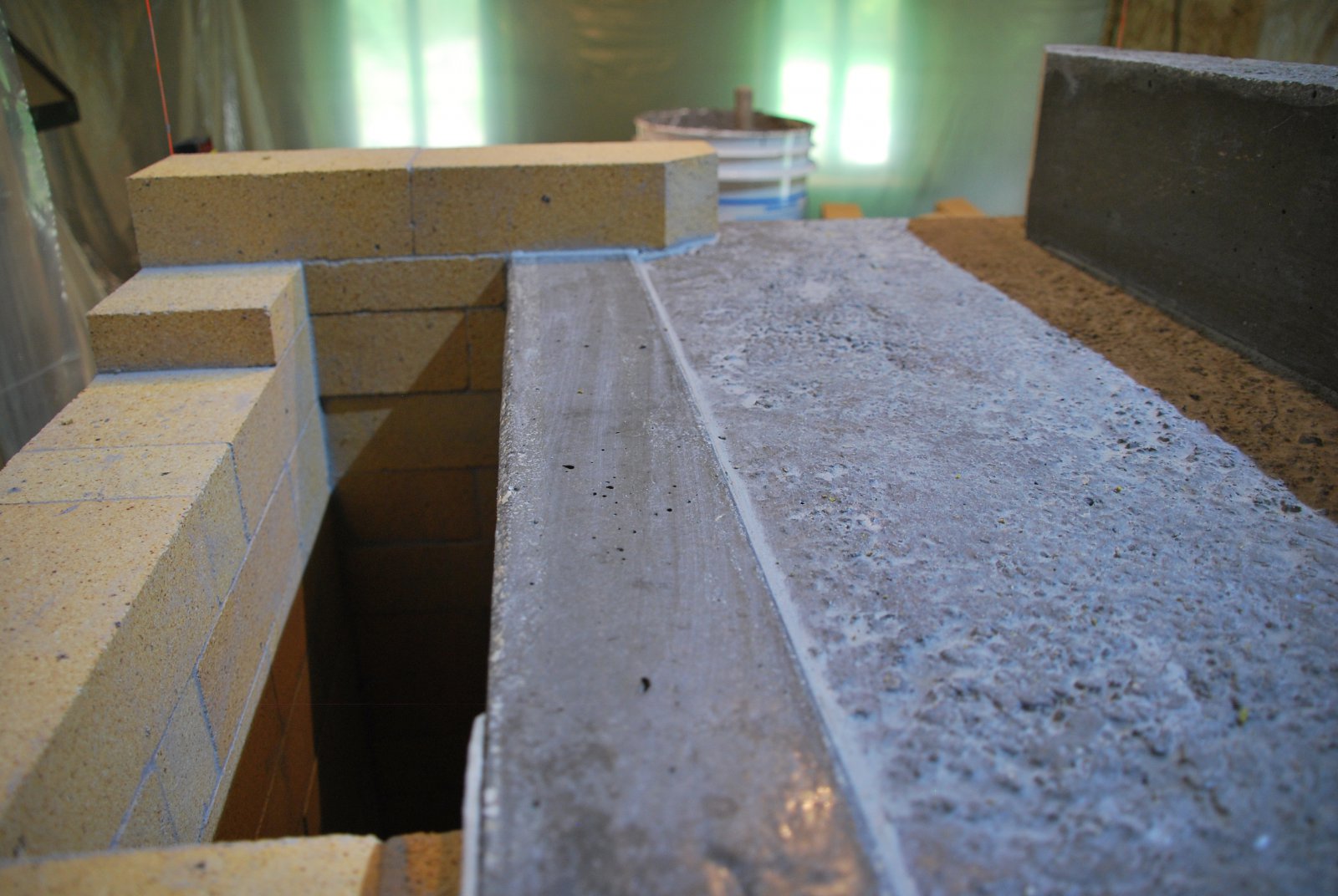
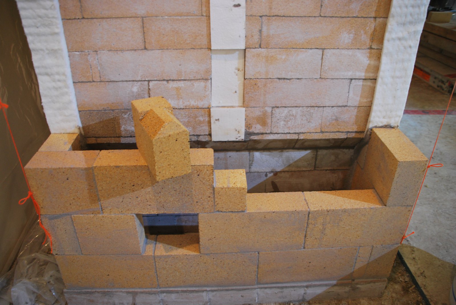
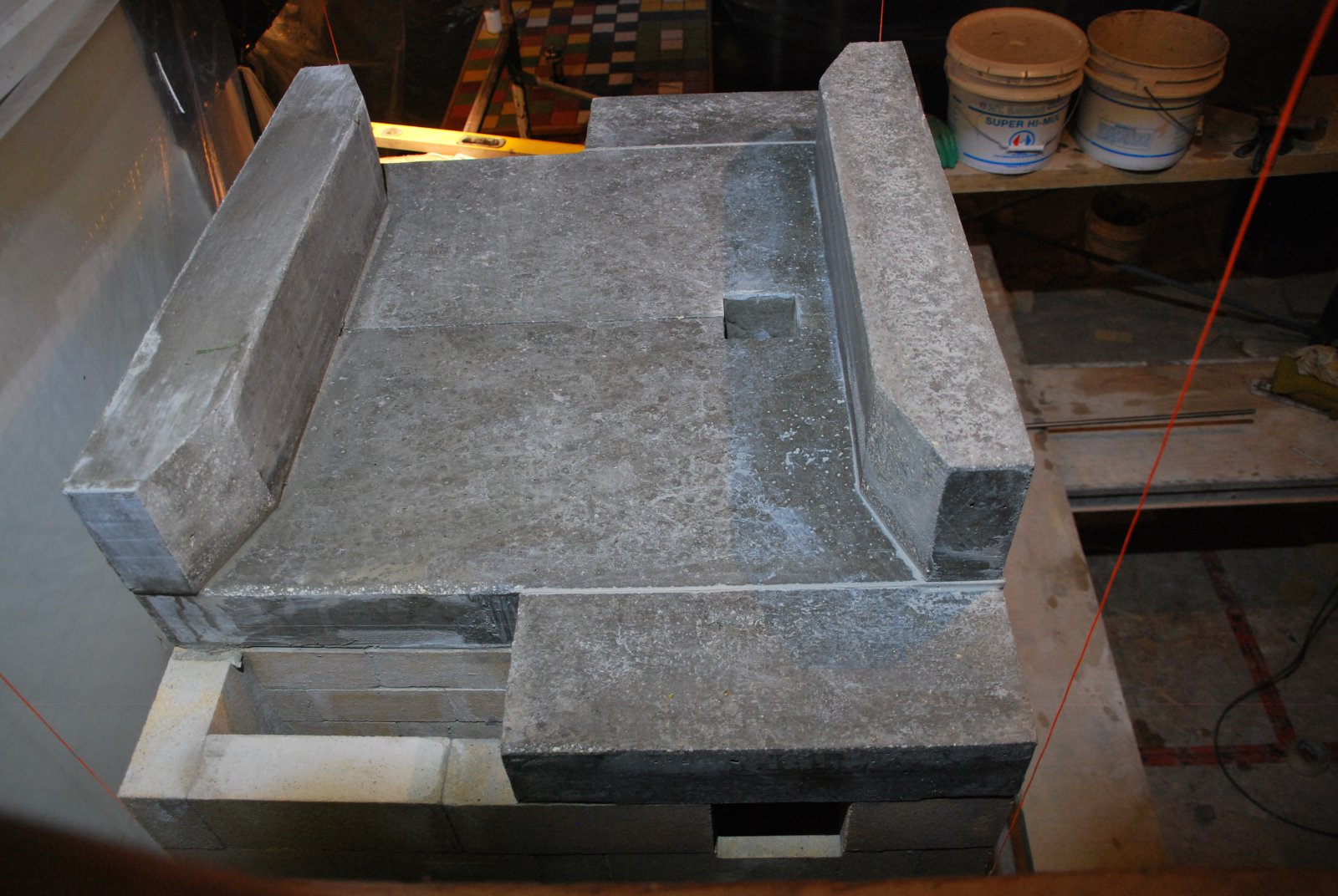
The side walls of the fire tube are extended over the back of the oven, to be vertically aligned with the dividing wall of the side channel. The pencil line represents the dividing wall. Note: The ovens rear slab is laid in HTC directly on to the brick bellow, as it will support the extended side walls. (The back slab of the oven in a contra flow takes no weight and so sits upon a paper gasket making it free floating.) In this case though direct hard contact is required. Note that the rear slab is gasketed with paper on the front and rear surfaces where they contact the oven walls, and the fire tube walls.
The portion of the brick that rests upon the ovens top slab however, has a paper gasket between it and the slab. The ovens top slab is laid dry, upon paper which acts as a smoke gasket, and so would offer no direct contact to the brick above. The paper that the brick is laid upon, acts as a smoke gasket to avoid even slight 'cross over' between the two sides of the divided channel.
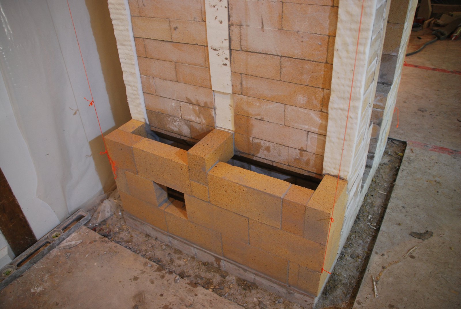
These extended side walls of the fire tube, deflect the stream over the oven and into the down channels. They also form the inner walls of the up channels.
The load relieving lintel, and the two side walls of the fire tube, have their inside corners cut to reduce turbulence in the stream.
The stream flows up the fire tube at the back, across the top of the oven and equally through the two openings at the front corners, into the down channels.
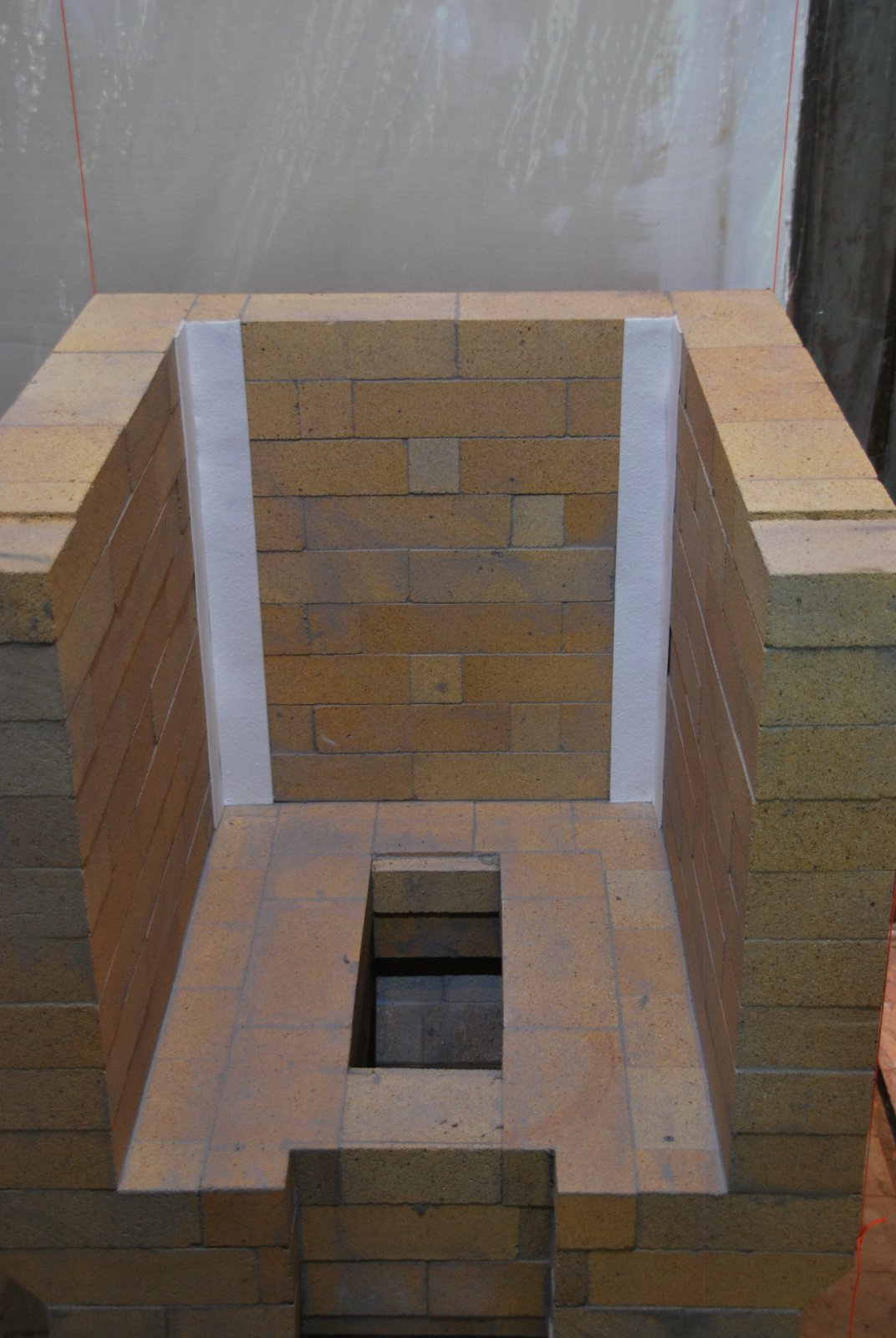
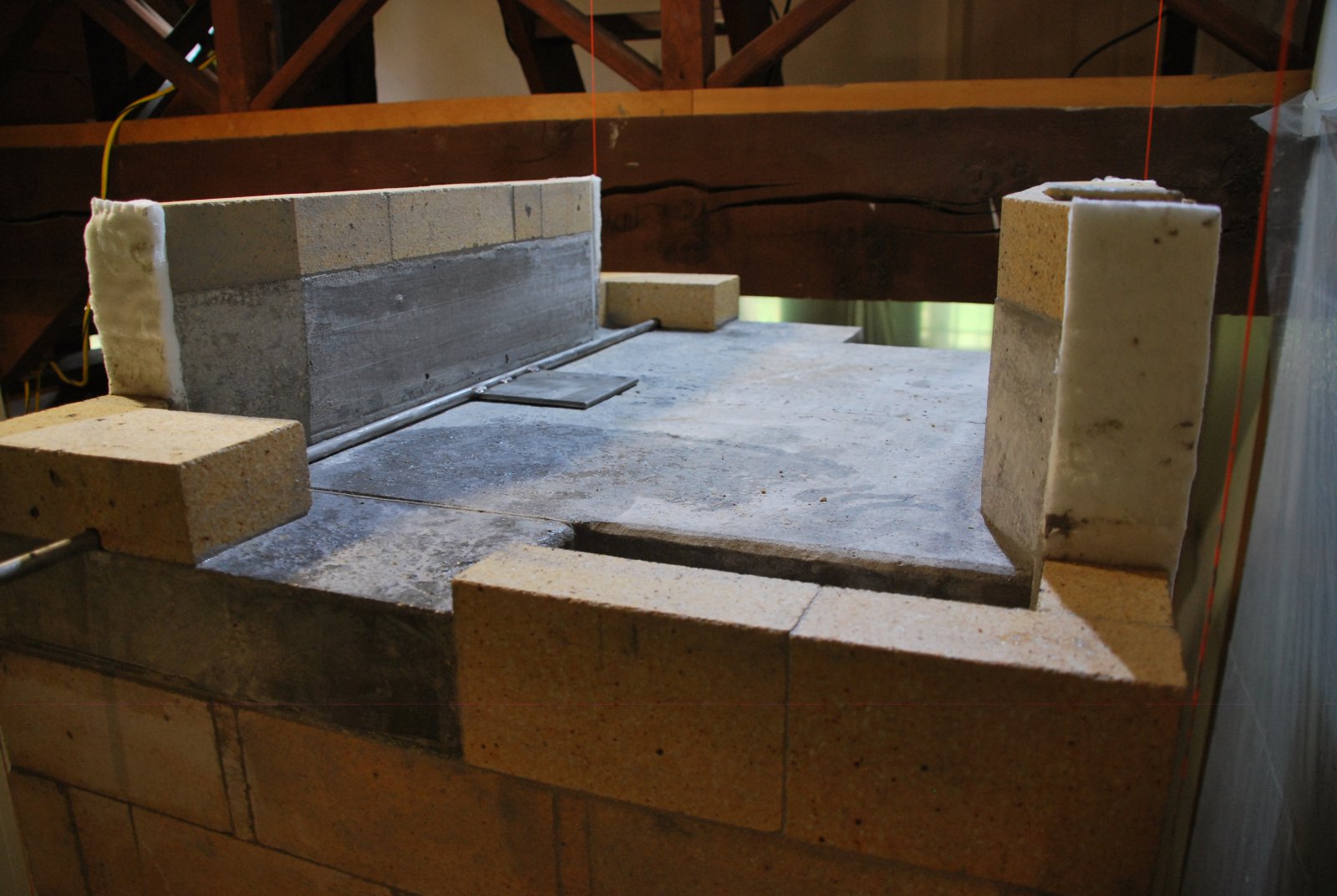
Gaskets are held in place on the core with HTC. The two ribbons of wool are laid where the side channels walls will but against the core. The channels dividing wall will be gasketed from the core with paper, as it would be almost impossible to remove, accidentally when cleaning. Or if it did fail and disappear it would leave only ⅛ of an inch space. Cross over from the top of the down channel to the top of the up channel could cause a serious loss of efficiency.
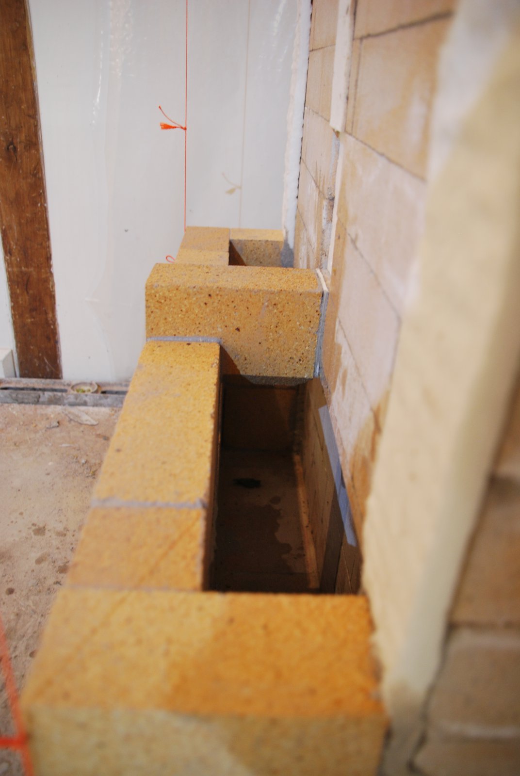
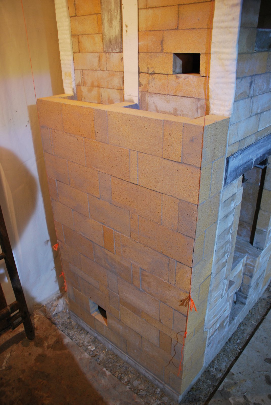
The start of the side channel. The two sides of the divided channel are connected at the manifold. The access opening is not located in the centre of the wall as it would be directly below the first dividing brick of the channel. Positioned to the left like this, it allows access to both the up channel immediately above it, and the down channel to the right and above. This access opening along with an identically positioned opening in the other side channel, offer straight vertical access from the manifolds, to all 4 channels.
The first dividing brick has to butt against the core as it is below the level of the recess that is cut in to the fire box wall to accept the second course of the wall. Cutting the recess a course lower would have meant the dividing wall rested on the weak tip of the skew cut course below. Starting the division at the same course of the recess, would make the cross over, at the bottom of the channel, too high. Here It is approximately 10.5 inches which is already slightly higher than necessary.
The rest of the channel is laid up to the height of the first dividing brick.
The second course of the dividing wall consists of a brick tied into the channel wall and resting dry in the recess.
The next course crosses and traps the second brick of the dividing wall.
This bond is followed to the top of the channel.
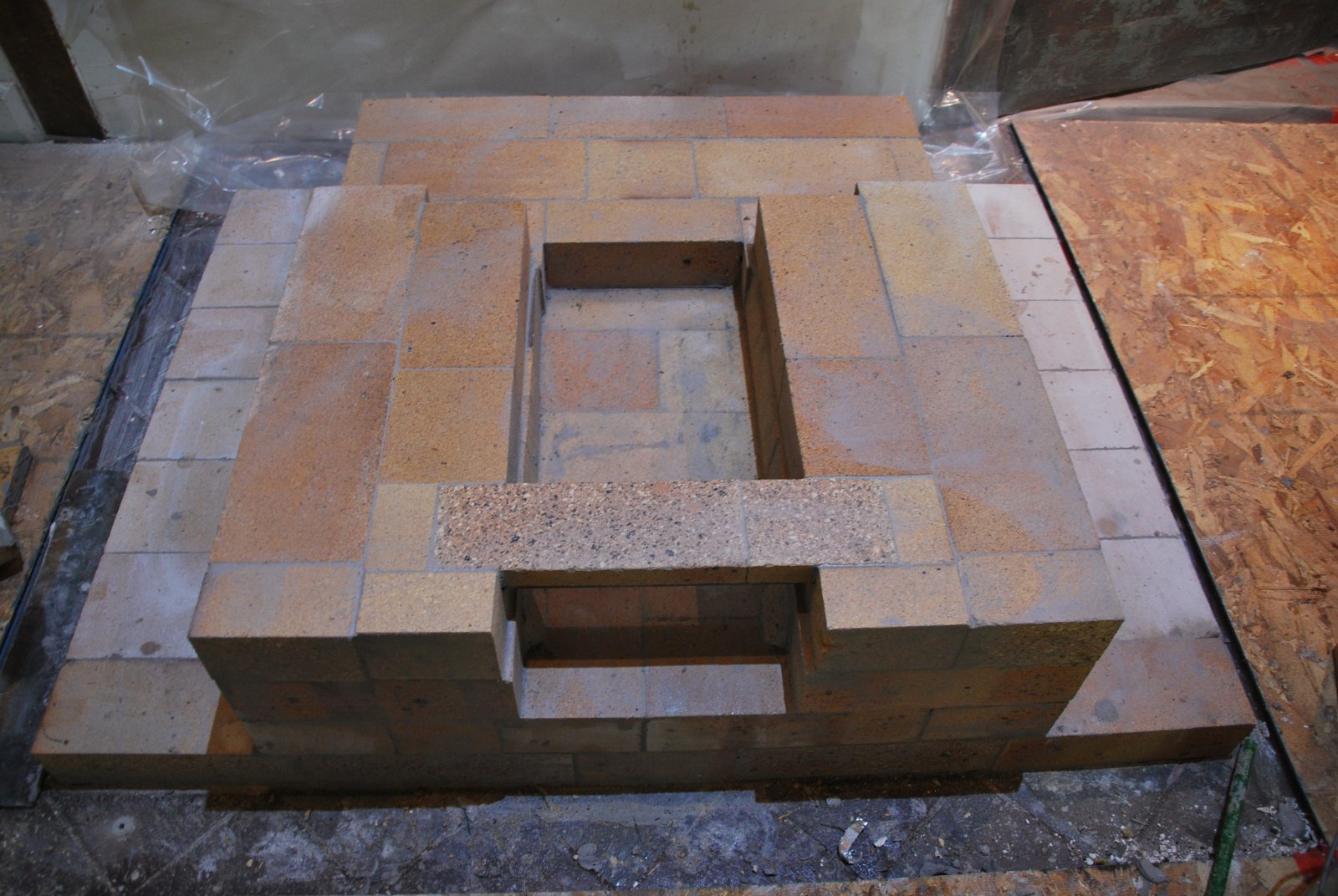
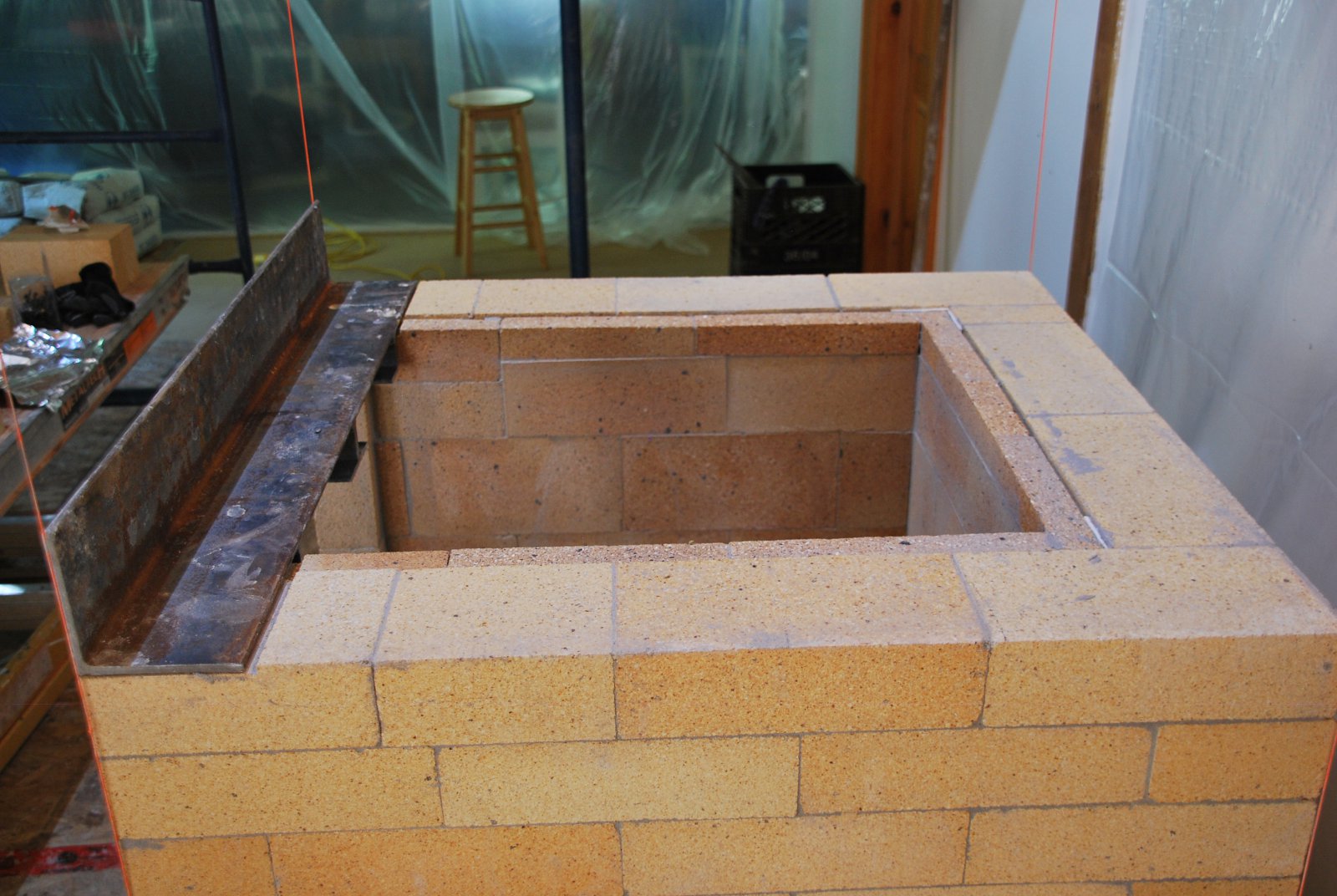
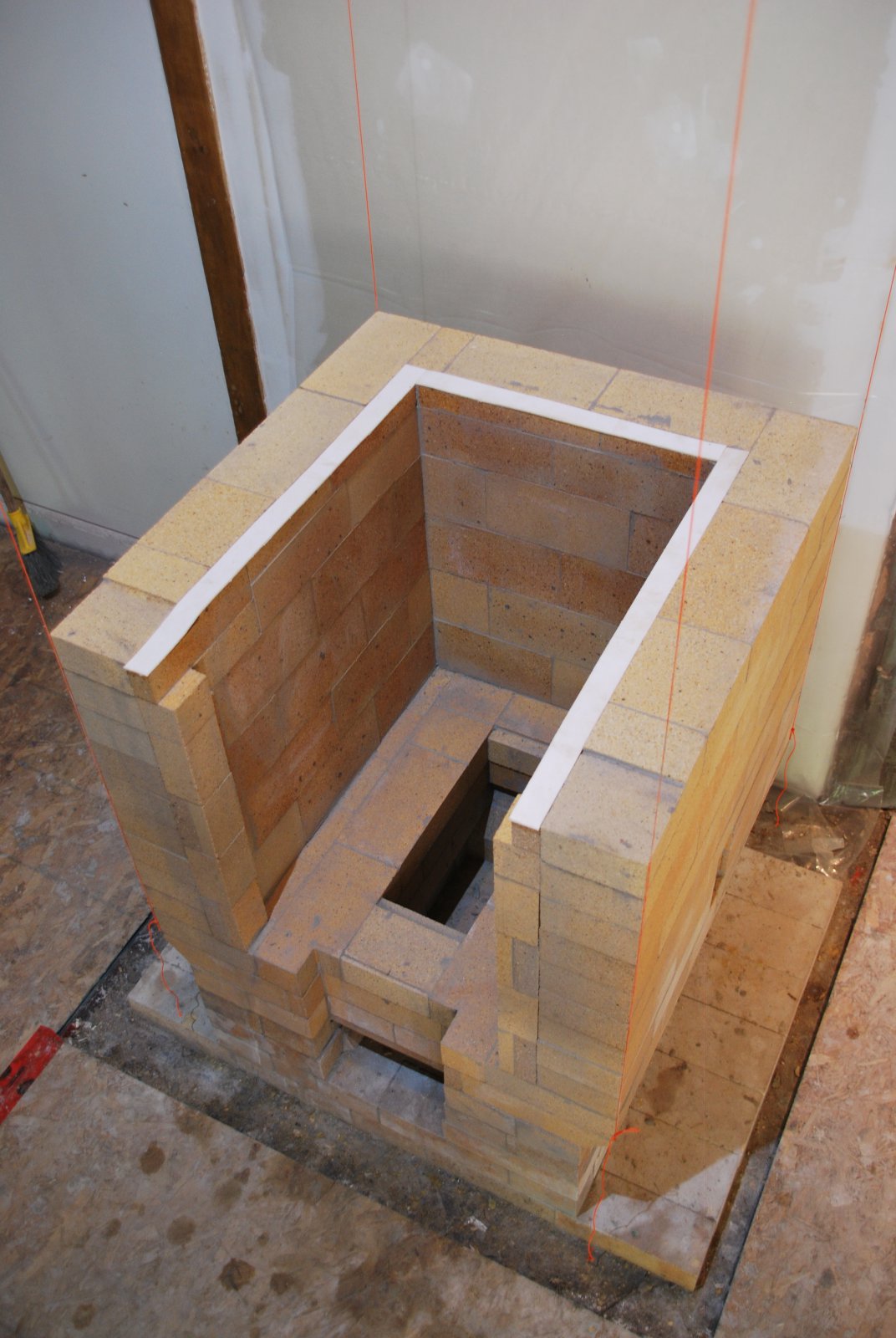
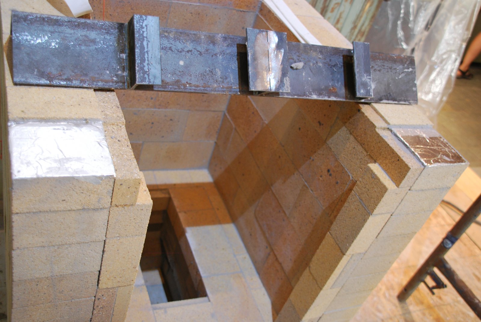
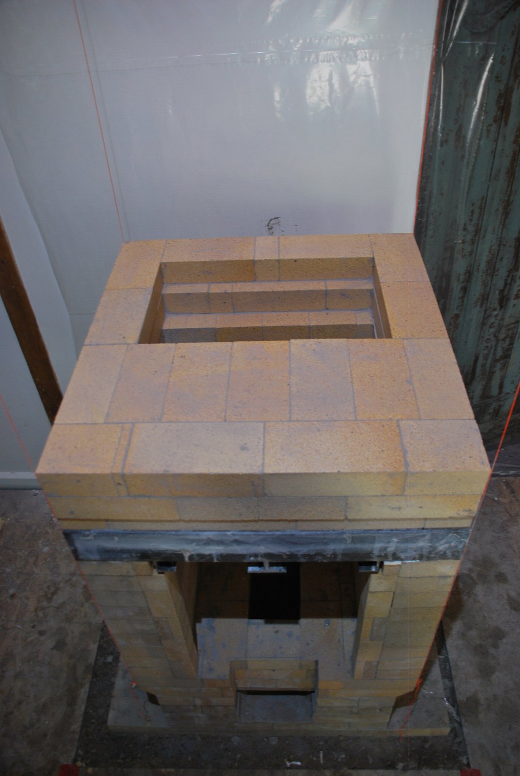
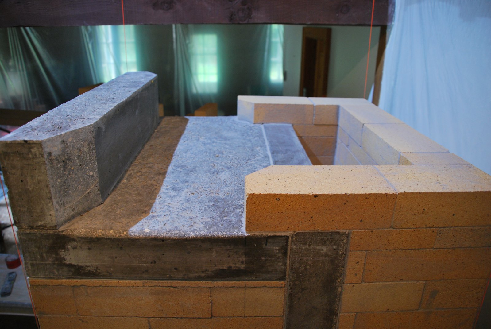
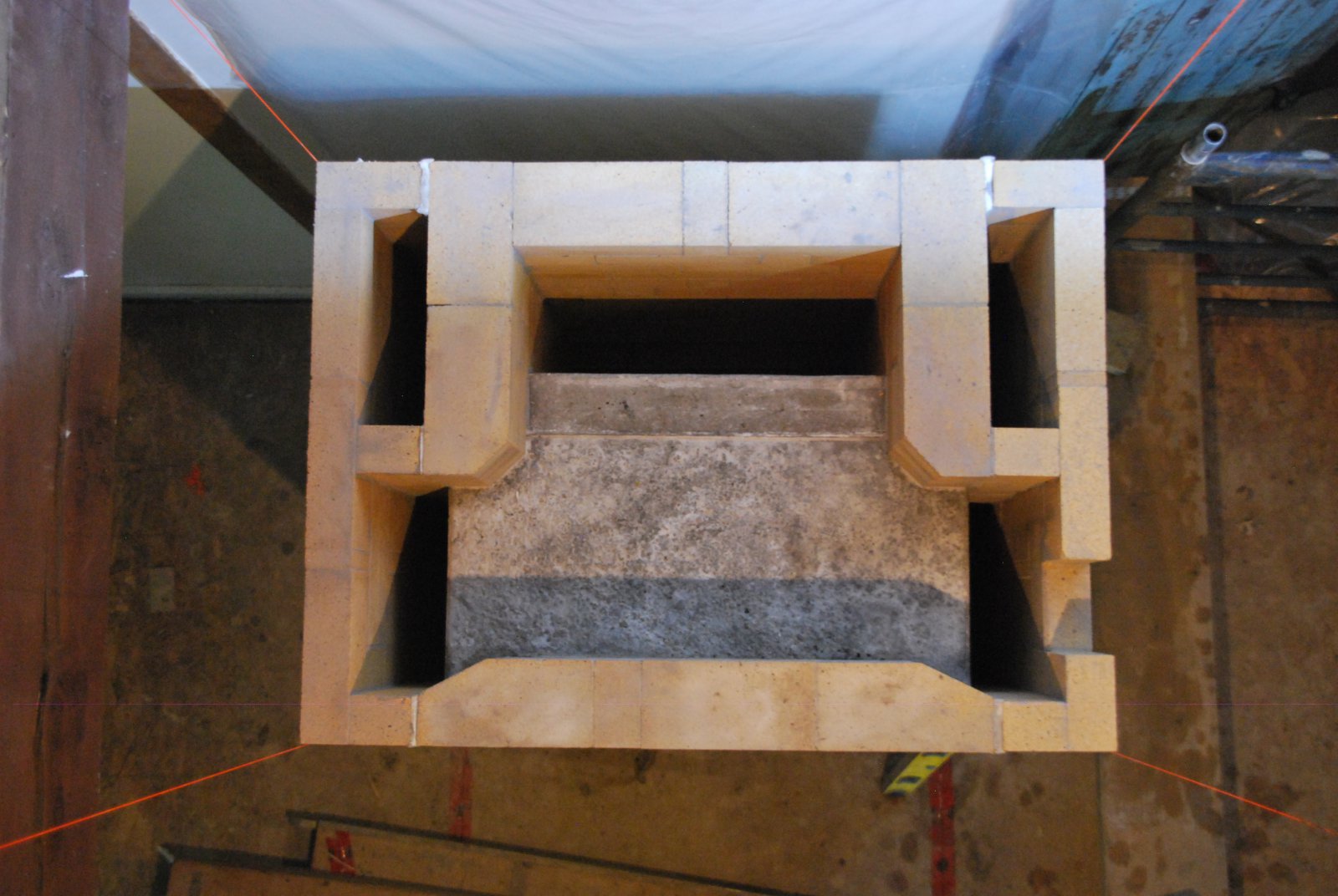
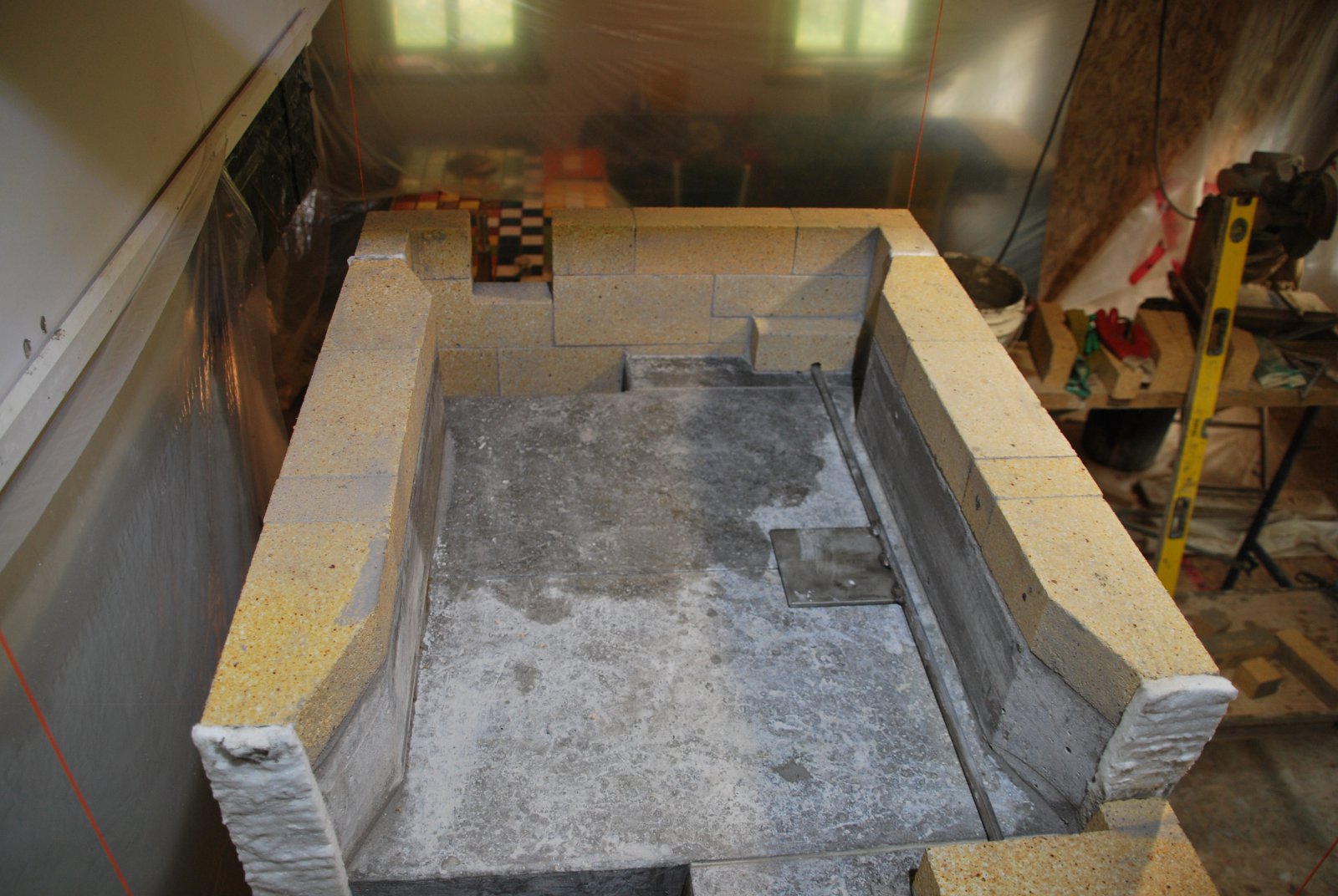
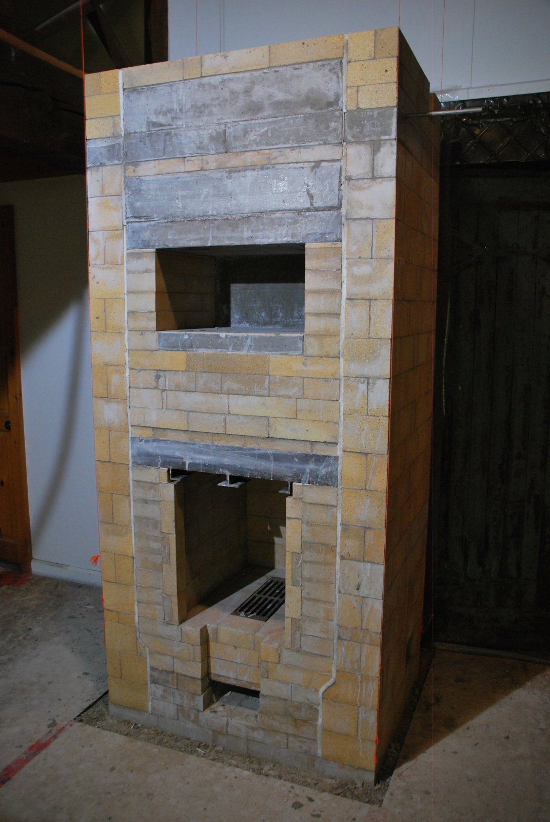
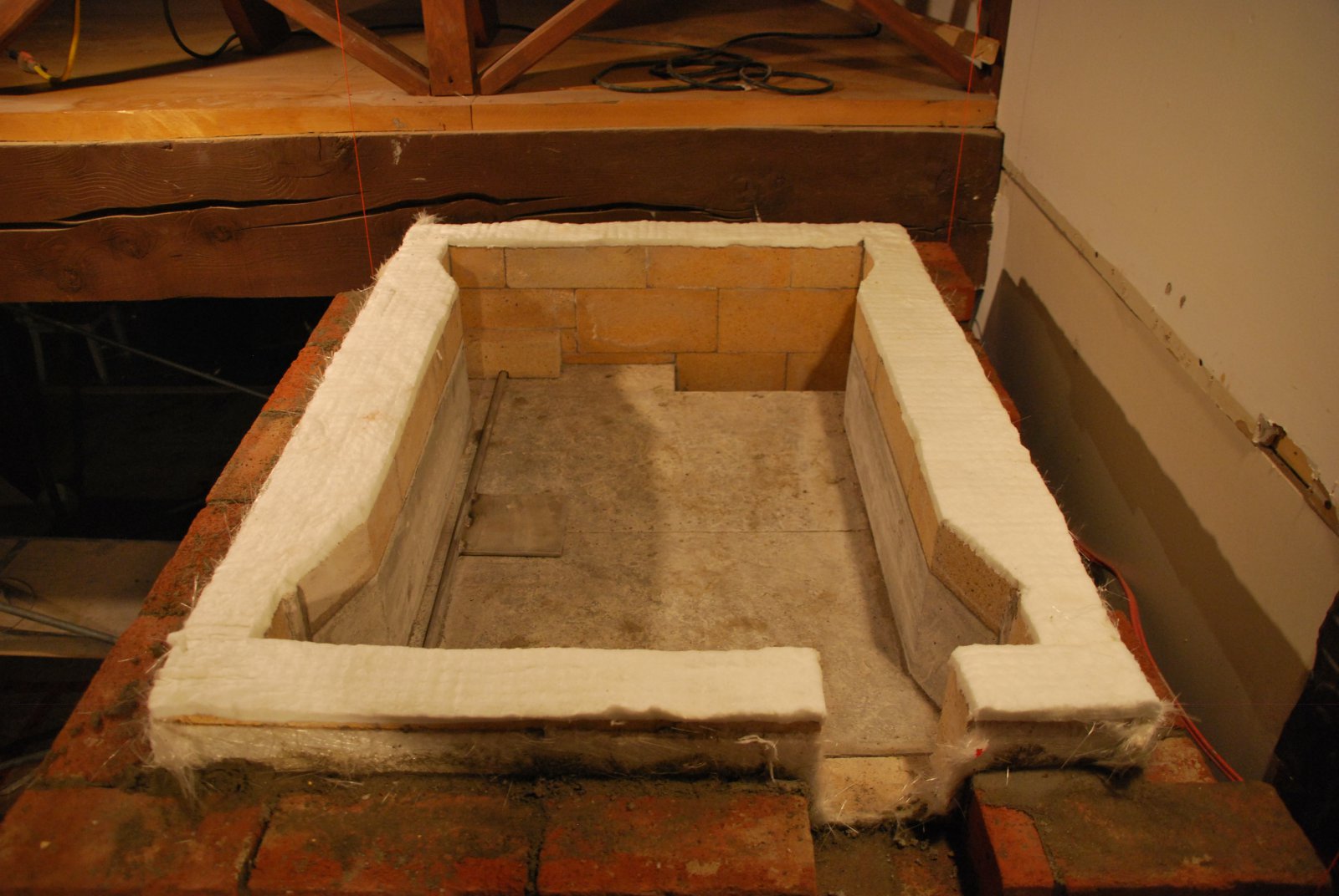
The core and side channels at the height of the upper chambers capping slabs. The fire tube is at rear, the upper chamber in the center, the down channels at the front corners, and the up channels at the rear corners.
Note: The opening in the top of the wall of the right channel, will be blocked, and the opening cut into the same position in the opposing channel wall (see image below).
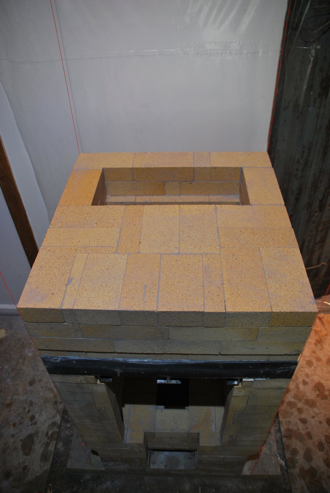
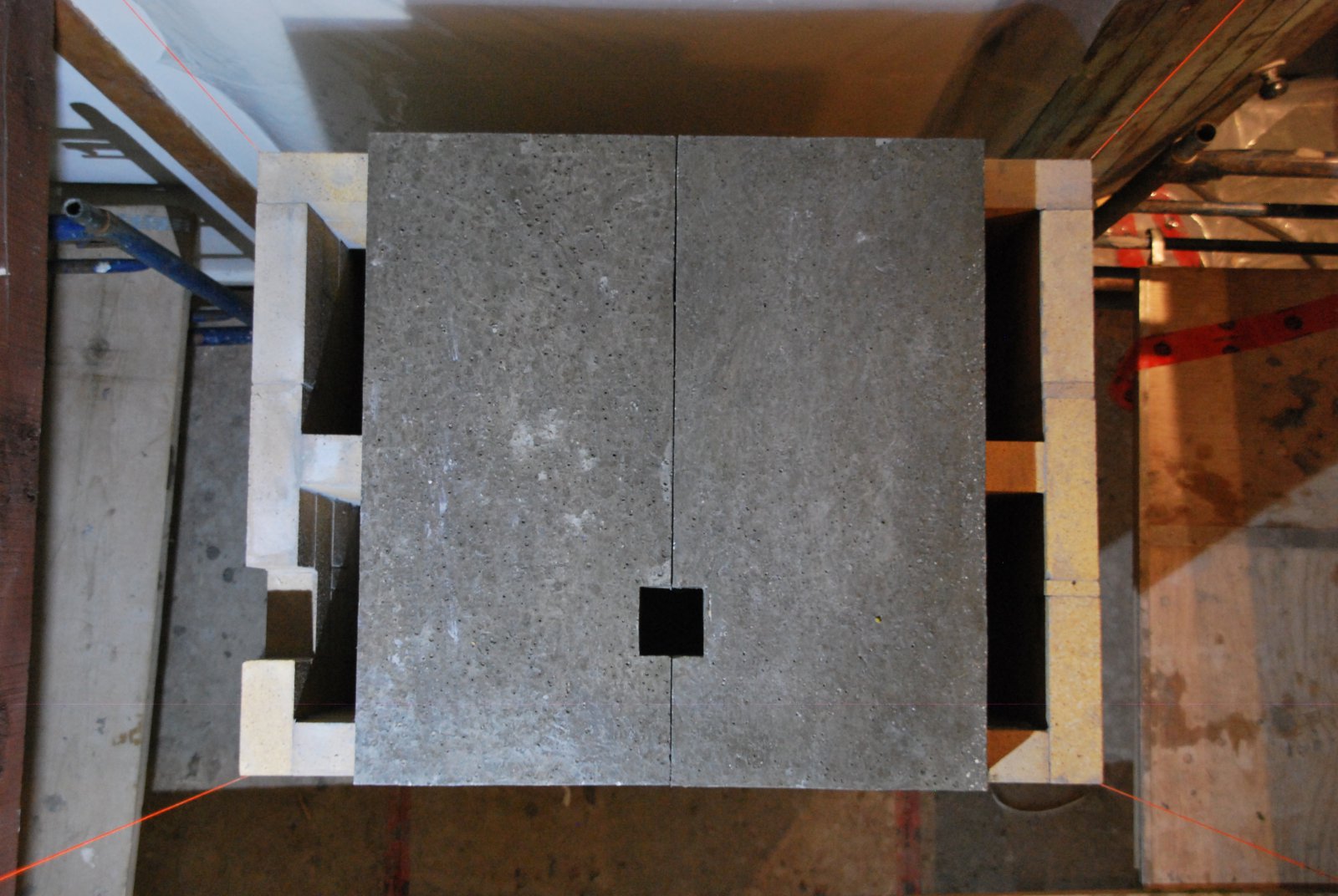
Two of the four castable refractory concrete slabs that close off the upper chamber. The square opening is to allow gases to bypass the down channels and enter the collector directly.
These slabs are laid in mortar on the rear and side walls of the fire tube, but laid onto a foil slip join on the front wall.
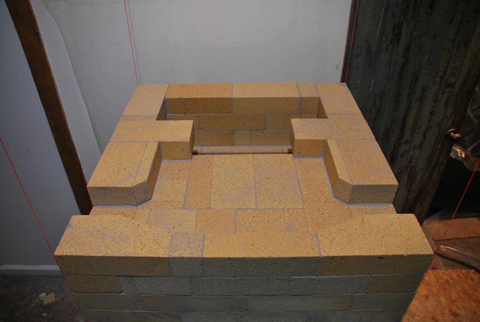
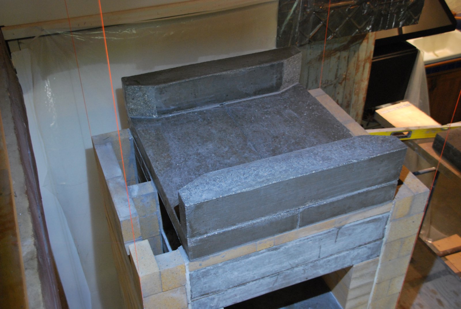
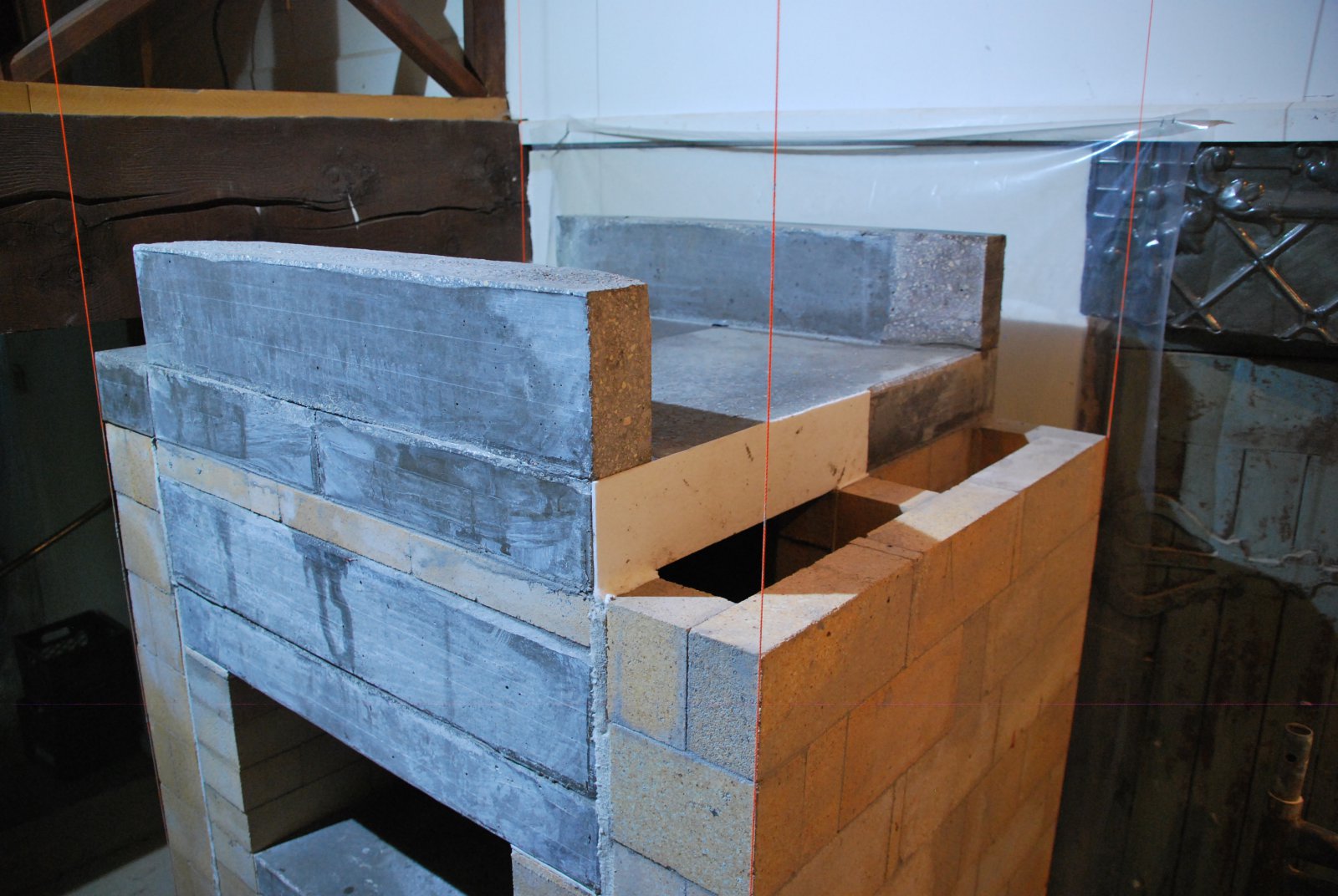
Two castable lintels form the front and rear walls of the collector. The lintel over the front is also a load relieving lintel.
Two smaller rectangular slabs are cast to cover the down channels. These slabs will be laid directly onto the channel wall in mortar. A paper gasket will separate them from the two larger slabs. This gasket maintains the vertical gasket of the side channel, keeping the channels separate from the core. If these slabs had been cast in two pieces, rather than four, they would have cross bonded from the core to the channels.
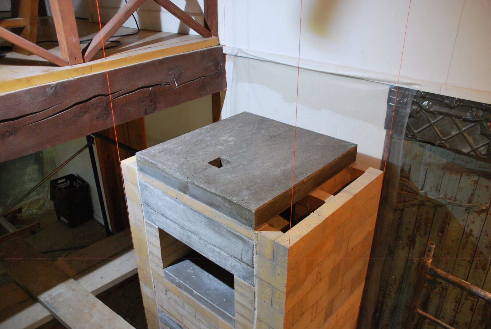
The four slabs that close the upper chamber, and the two lintels of the collector.
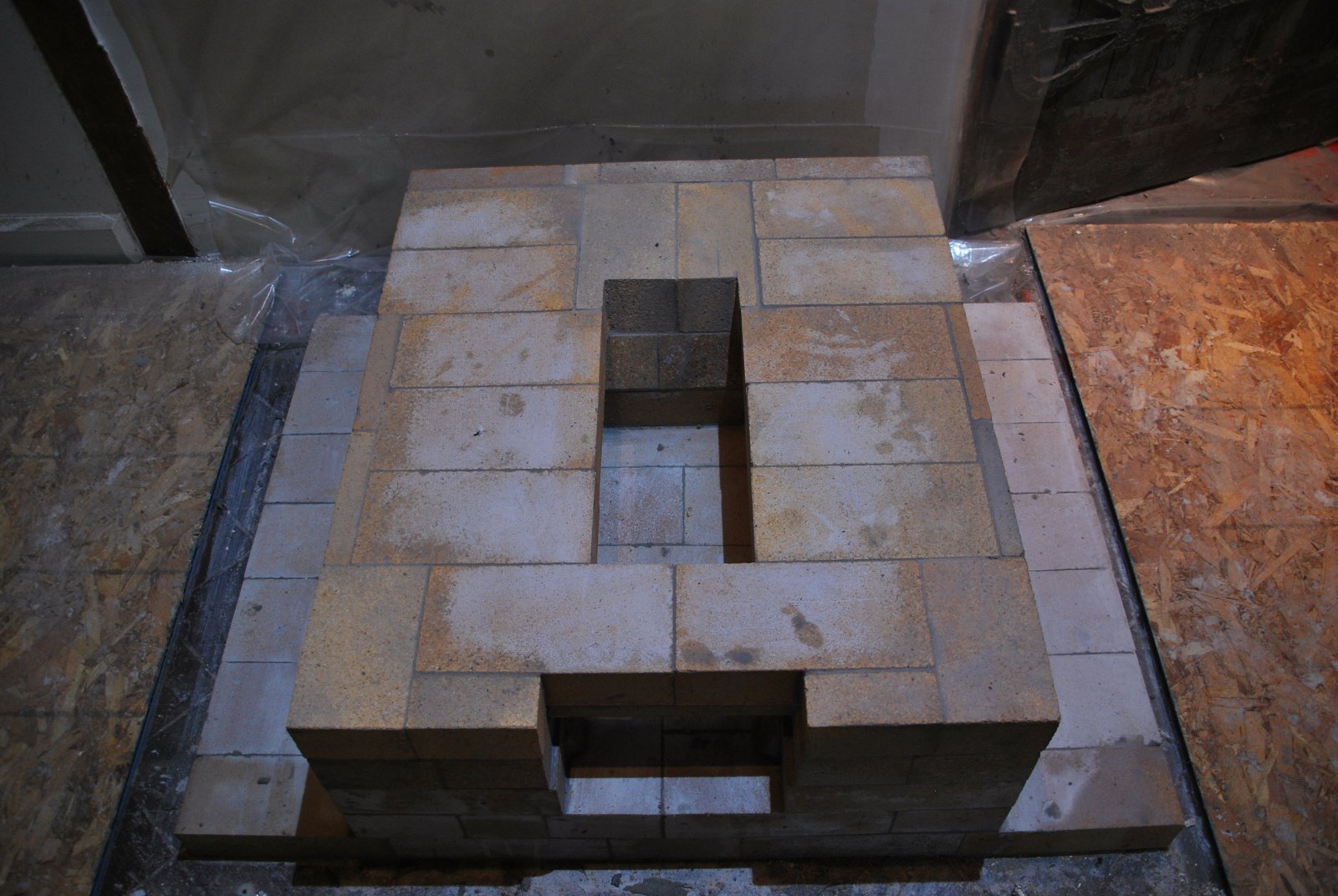
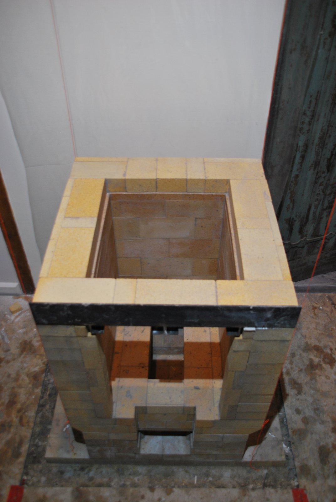
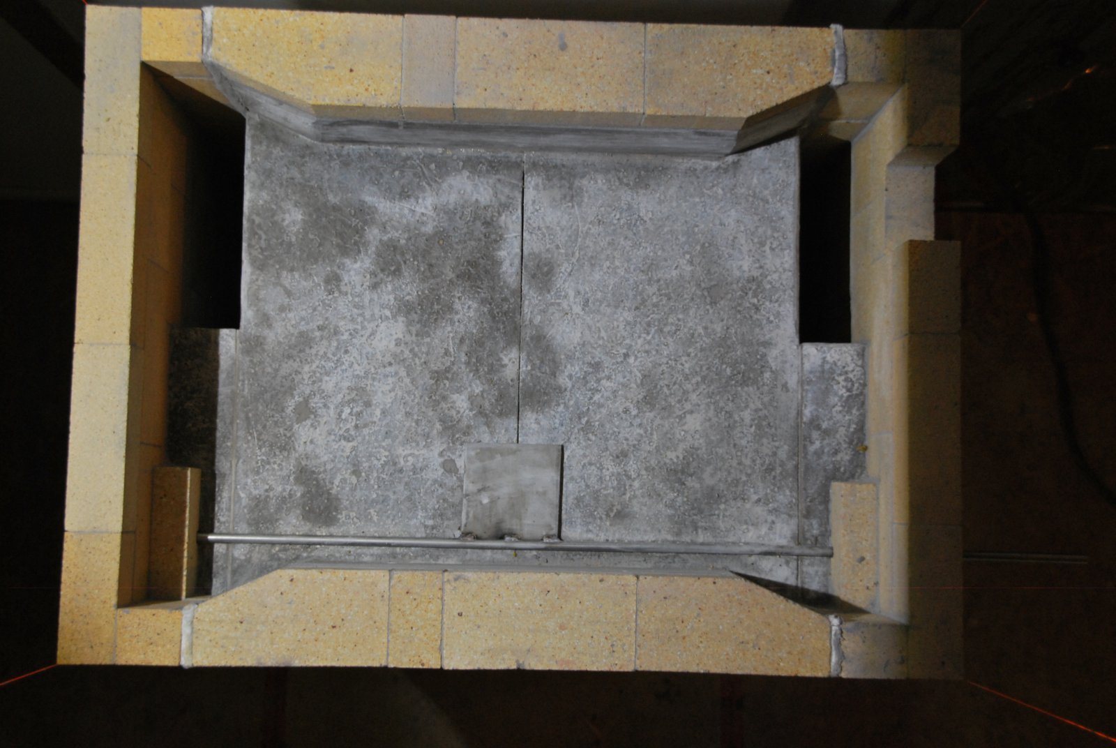
The upper chamber and down channels are closed off, leaving the up channels to feed into the collector.
The bypass damper consists of a half inch stainless steel rod and quarter inch plate. The operating rod is held in position by the first two brick of the continuation of the side channel. These brick are laid flat to offer more support to the operating rod.
Note that the channels are gasketed right to the top of the collector.
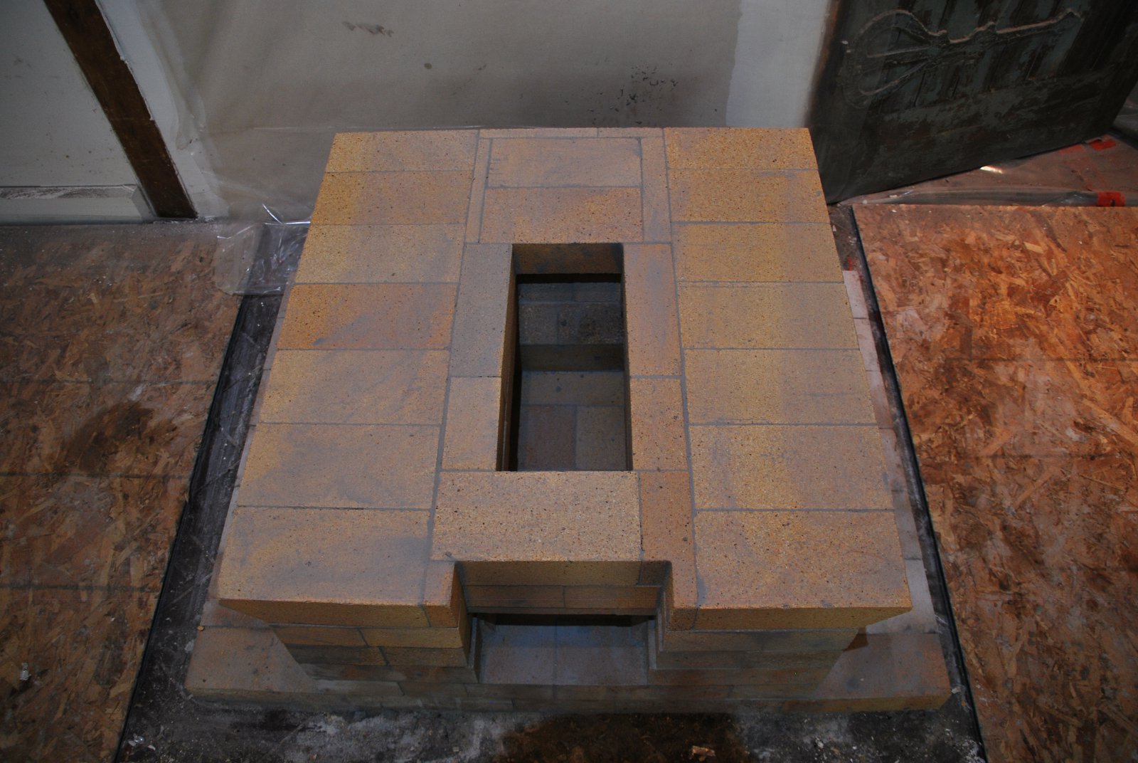
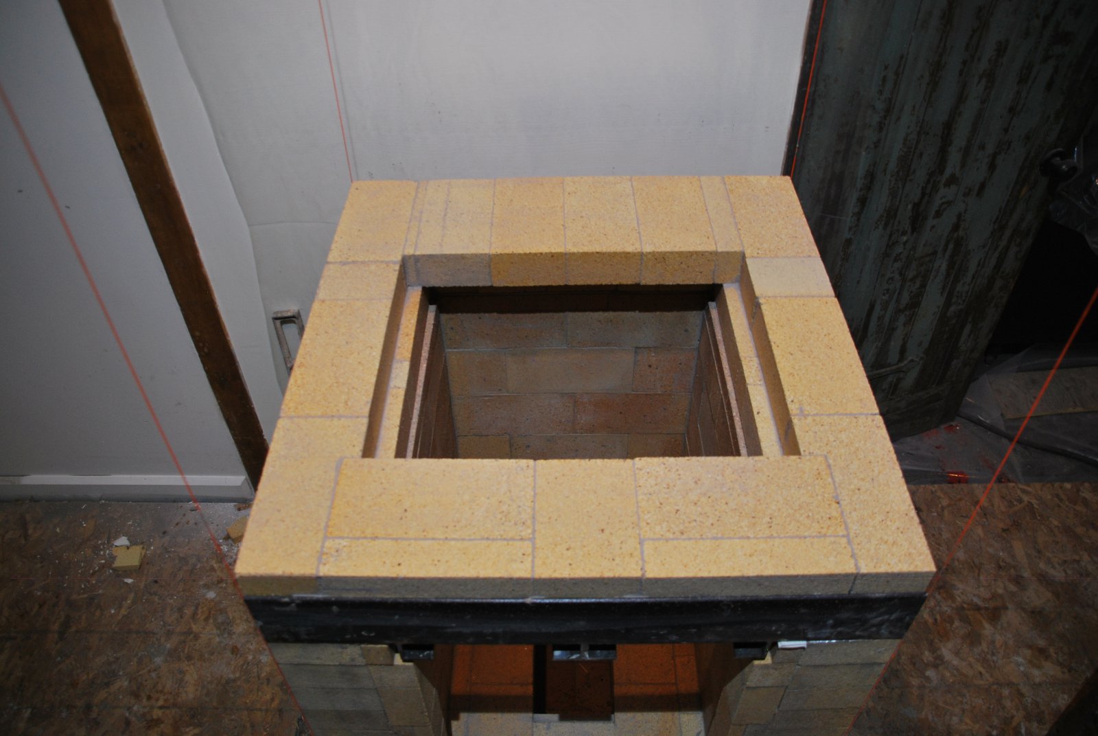
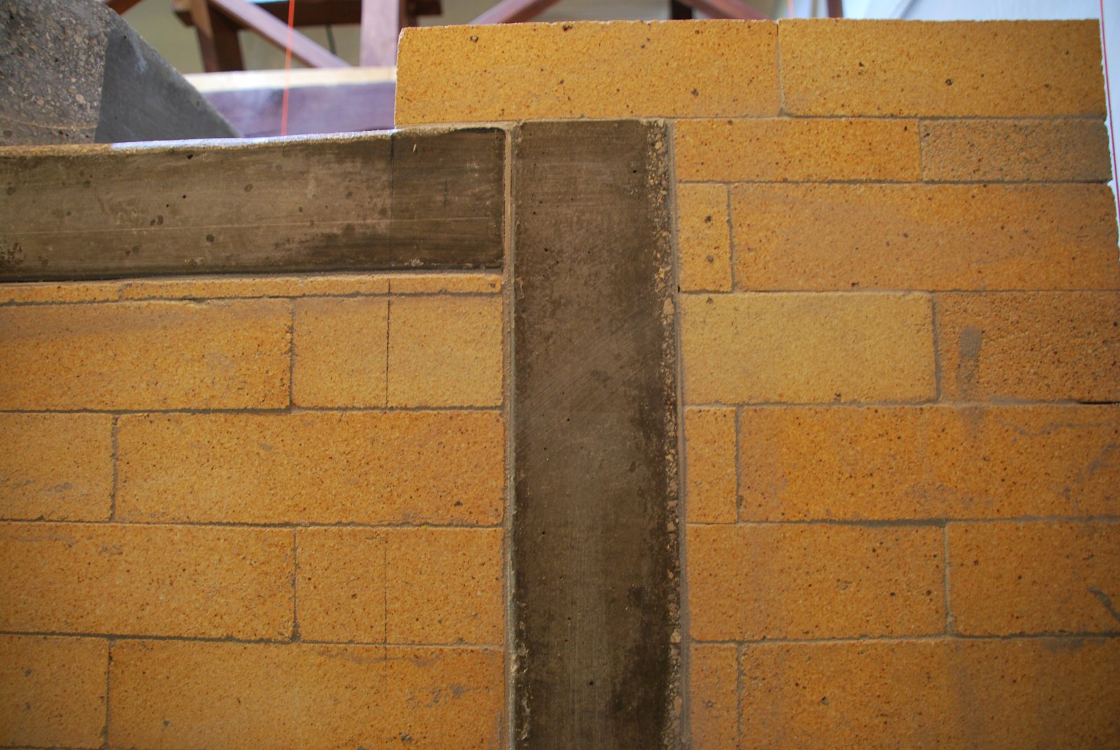
The completed collector. The opening in the channel wall to the right gives access to the chimney connection, and the upper portion of the up channels.
The bypass damper in open position. The location of the opening is not ideal as there may be an accumulation of fly ash against the load relieving lintel, which could compromise slightly the dampers operation. By necessity in this project, the bypass damper, and shut off damper operating rods, and one access door have to be located in the same side of the facing, at the same height. Care needs to be taken when deciding their location, that their handles do not interfere with each other when operated.
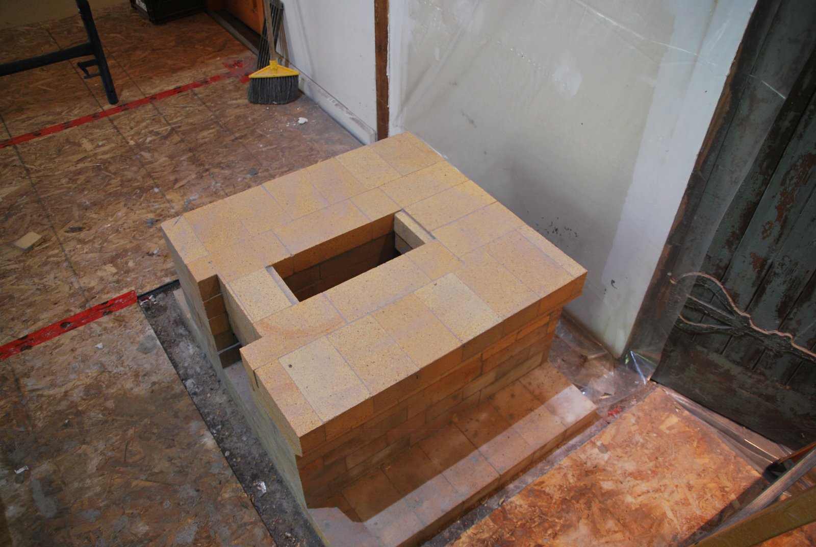
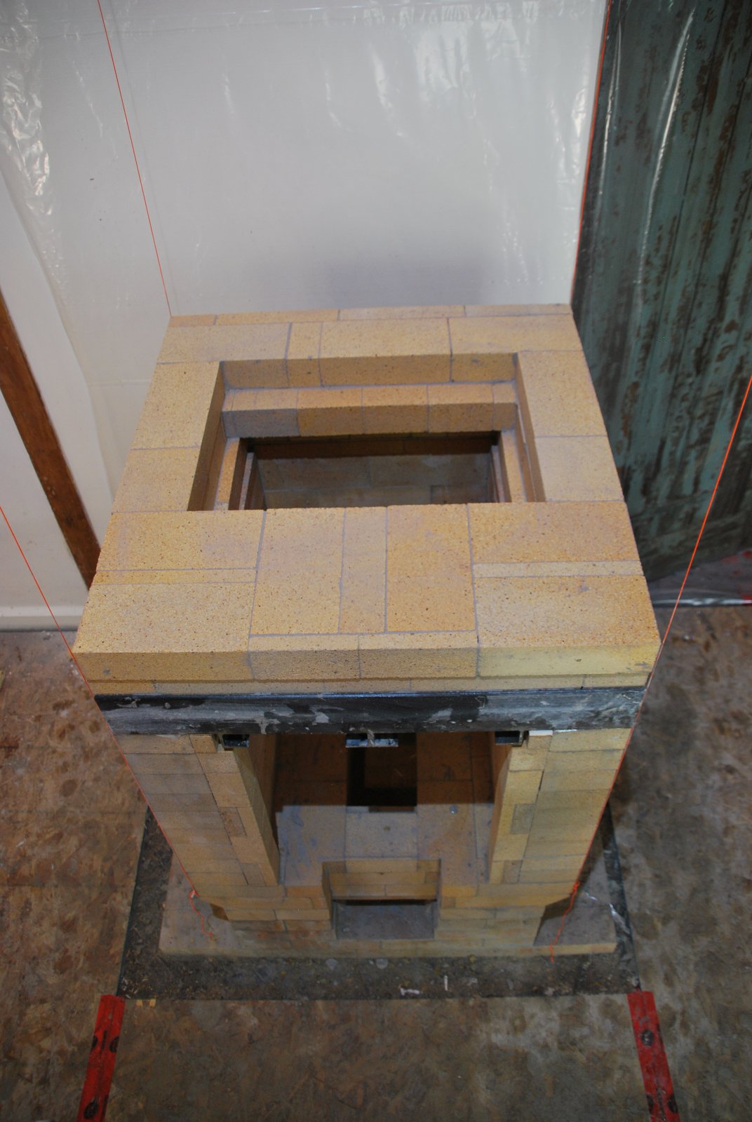
The completed core, less its final capping slabs.
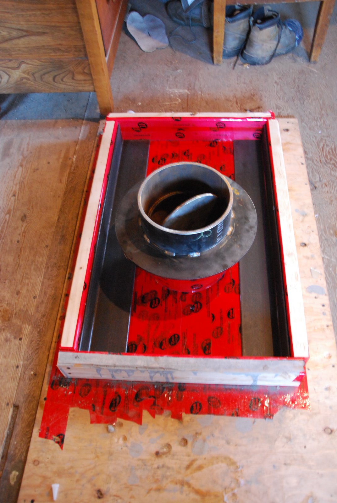
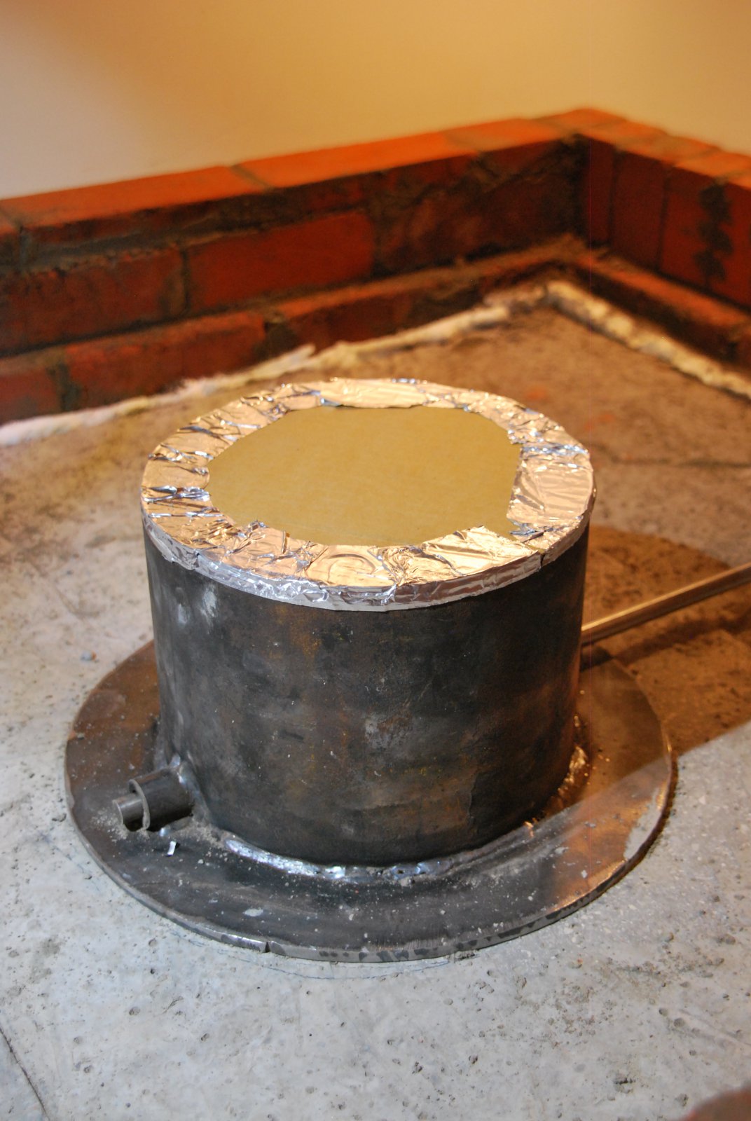
The mould set up for the widest of the three capping slabs, ready to poor. The chimney connector is positioned and gasketed with a ¼ inch of cardboard covered with tape. Two pieces of 3 x 4 x ¼ inch angle bar are laid along each bottom corner.
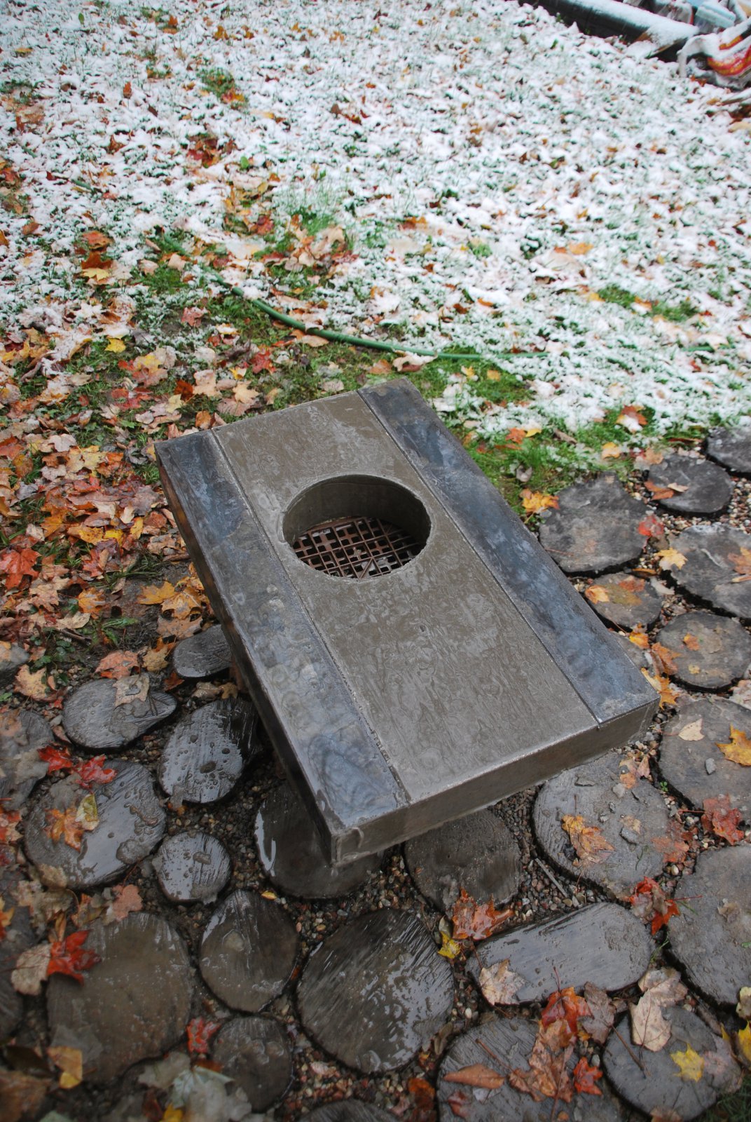
The deformed slab, seen upside down, resting upon a plastic crate. The kerf of the grinder blade has been removed for a quarter inch along each edge of each angle bar, to allow for any expansion. The angle bars have been added in case the slab were to crack due to the weakness caused by the 9 inch diameter opening.
The upper surfaces of the collector are gasketed with wool before positioning the capping slabs.
The three capping slabs, with the connector.
The two angle bars that support the central slab, will be able to expand lengthways into the space between the core and facing.
The slabs are gasketed against the facing with wool rather than glass mat as wool also acts as a smoke gasket.
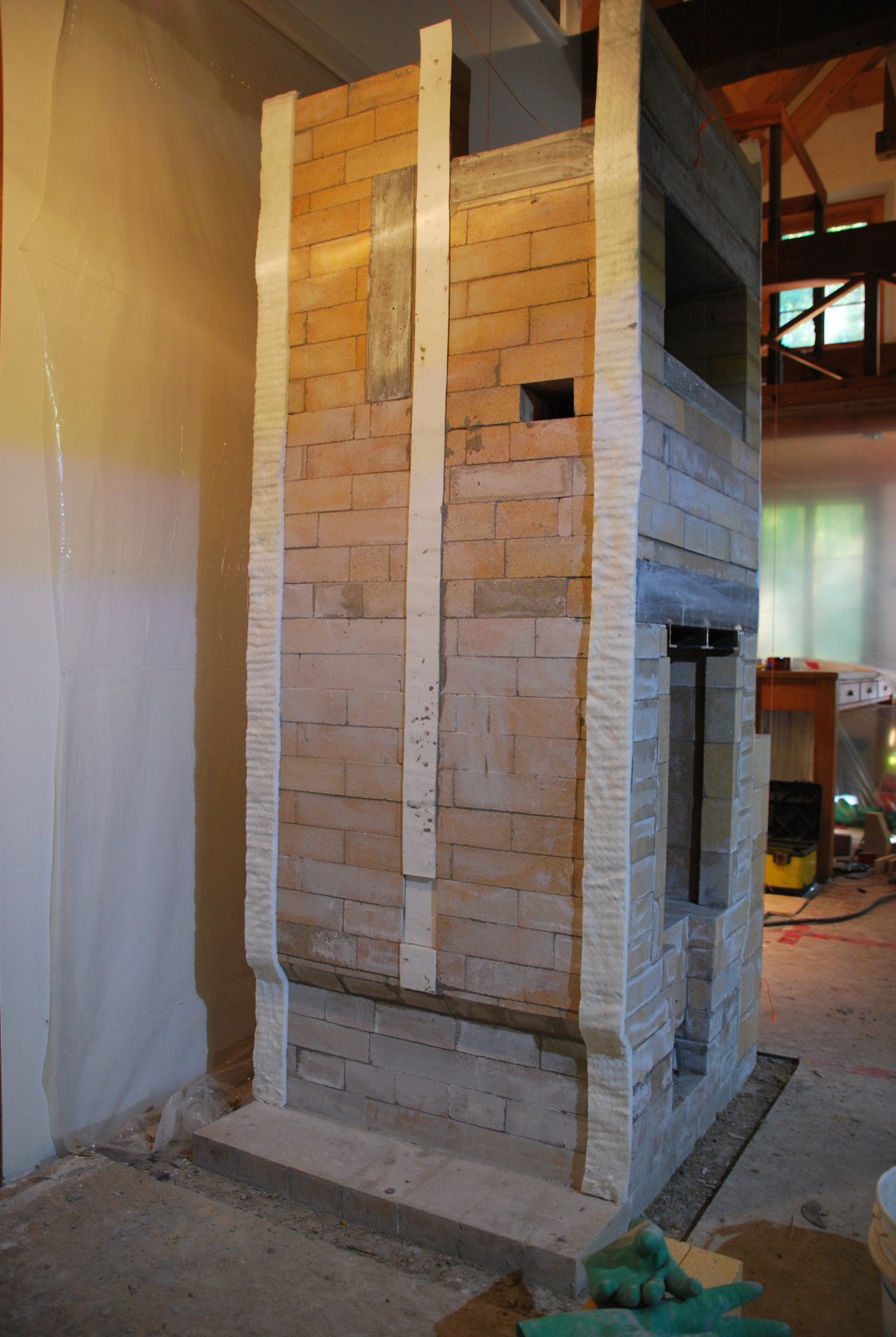
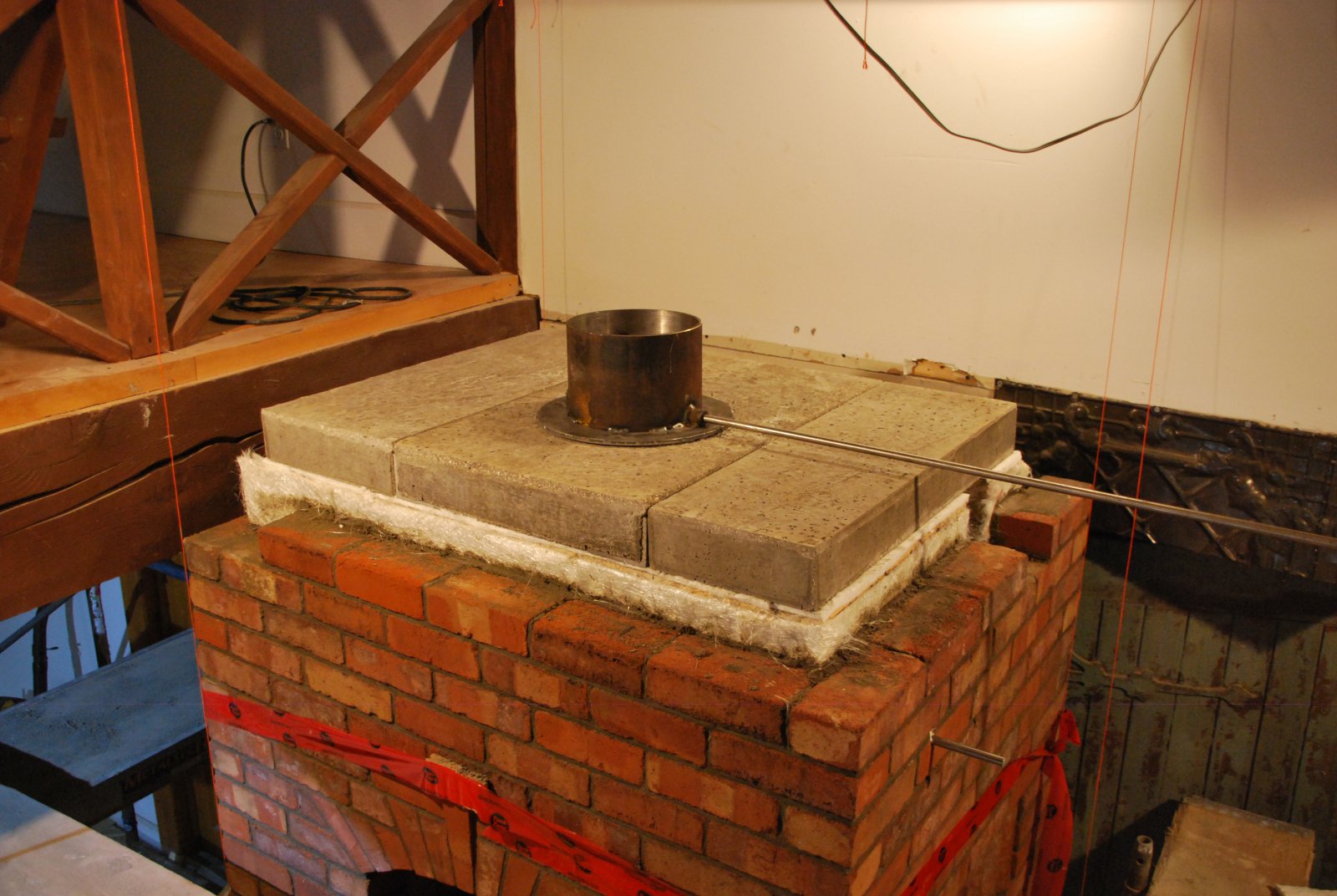
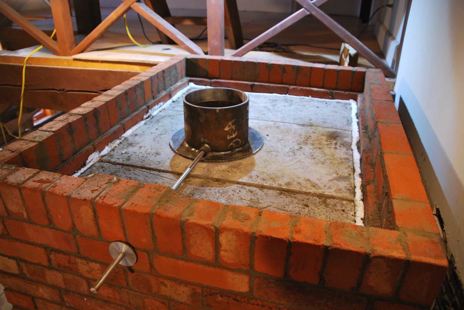
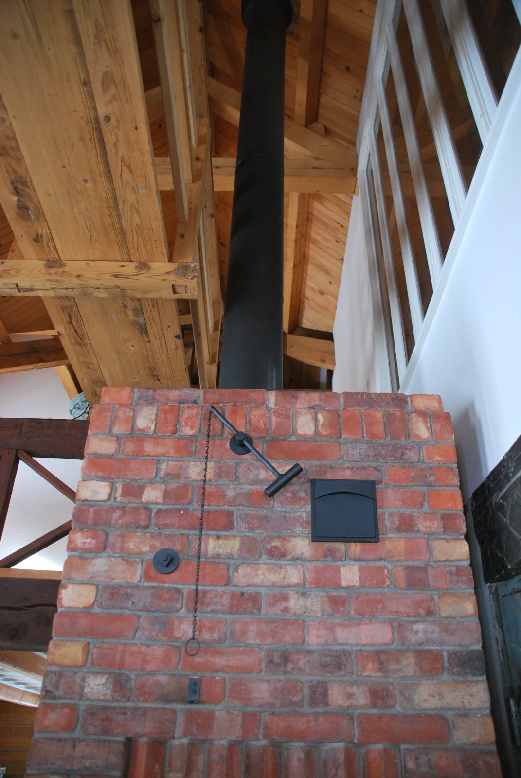
The connector and its damper control rod, protruding through the facing. Note: The last row (of headers) is cut back to 3 inches in order to leave an exposed horizontal ledge, of three quarters of an inch, on the course below. This ledge will be directly contacted by the concrete of the final common concrete capping slab.
The course of headers, is the penultimate course of the facing.
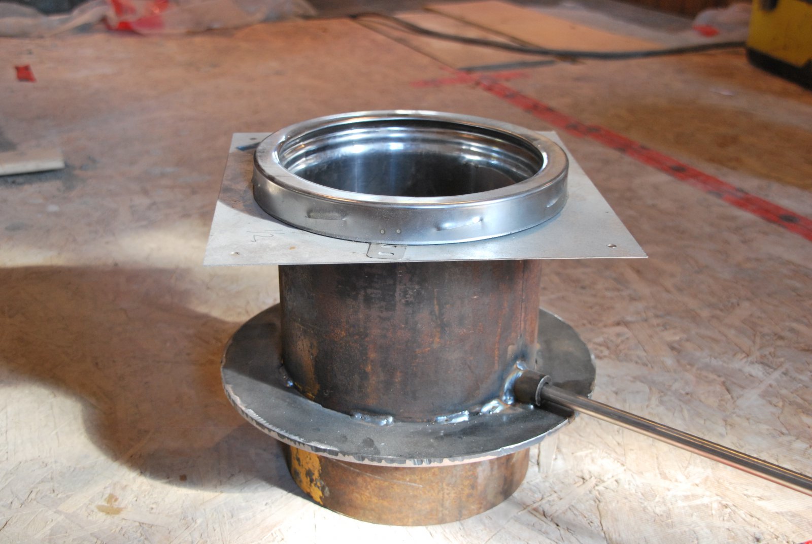
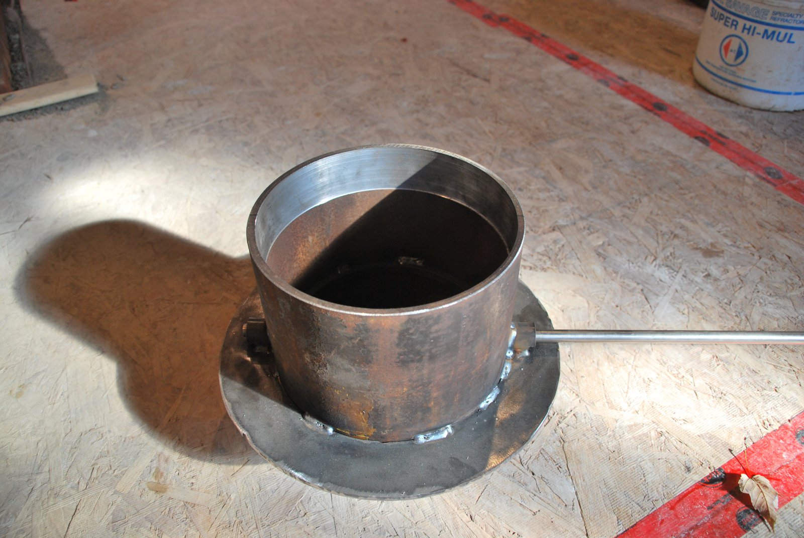
The connector is made from a piece of 8 inch ID pipe. The chimneys anchor plate protrudes down into the pipe.
The top of the connector has been reamed out slightly to allow the lower flange of the anchor plate to slide freely as the core, and collector rise.
The damper is installed inside the connector, and is operated by the handle to the right. The damper is seen here in the closed position. The plate has a 5% cut out to comply with ASTMe1602 A quarter turn of the rod clockwise and it will be fully open.
In order for the slip joint between the connector and the anchor plate to be effective, the concrete slab on which the anchor plate is installed needs to be cast slightly higher than the top of the connector. Two pieces of ⅛ inch thick cardboard are used to increase the height of the connector, and form a height guide when pouring the slab.
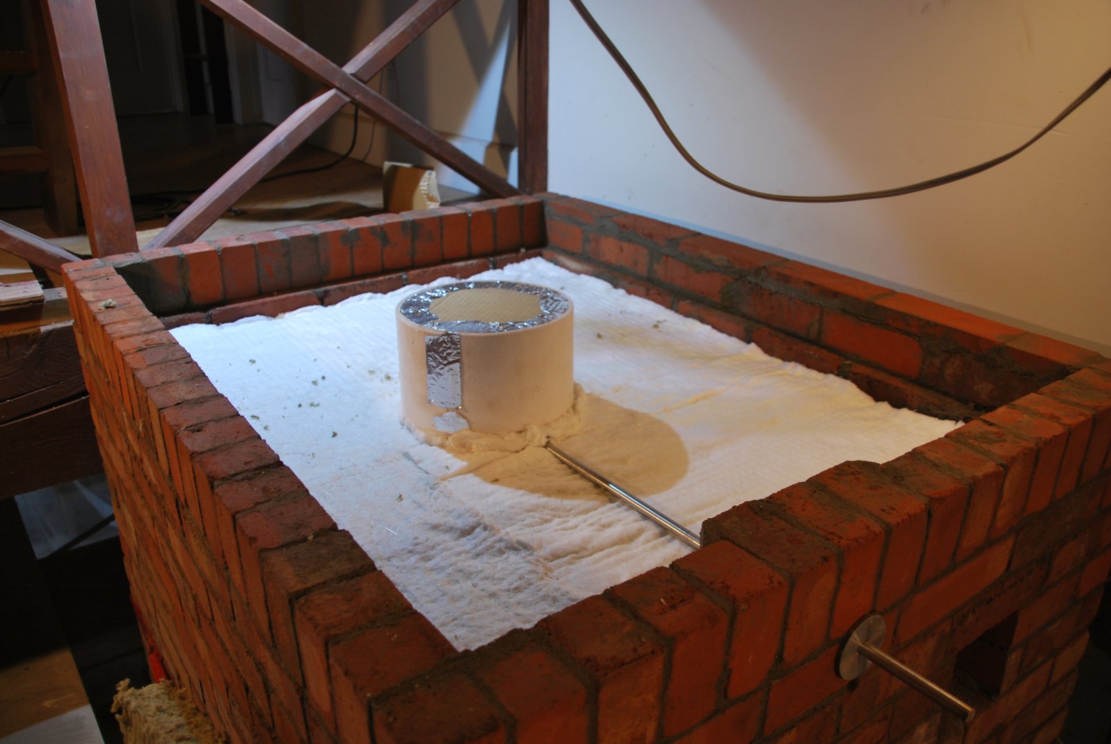
The connector is gasketed with 2 sheets of ⅛ inch ceramic felt. One sheet of wool is laid onto the upper surfaces of the capping slabs.
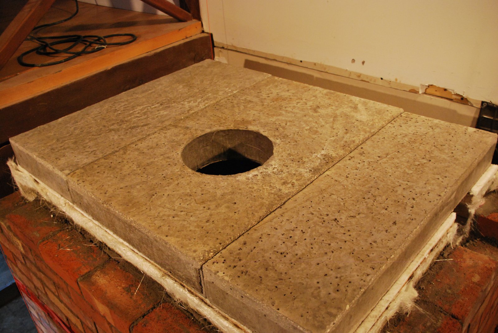
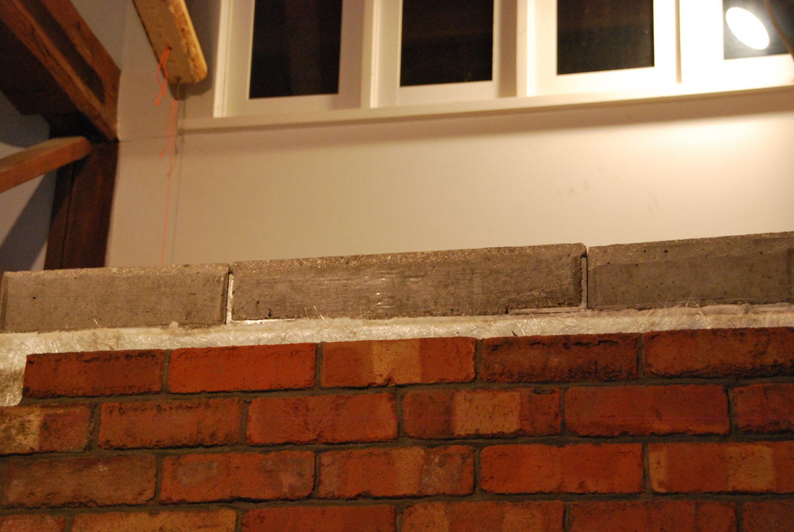
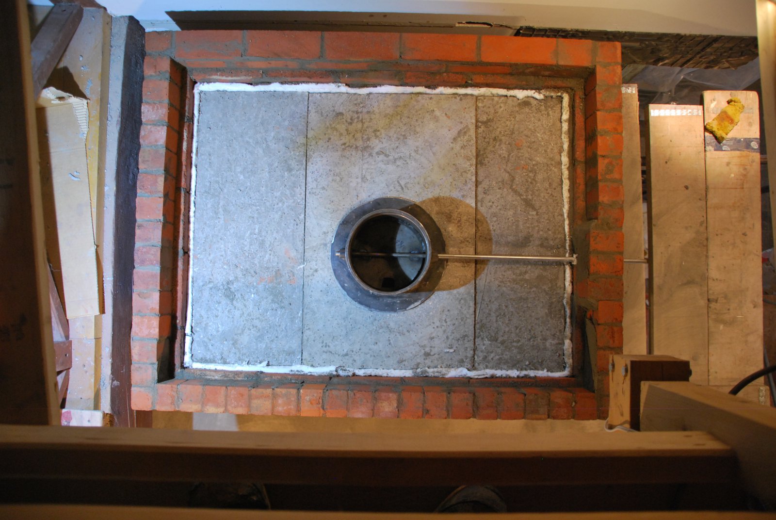
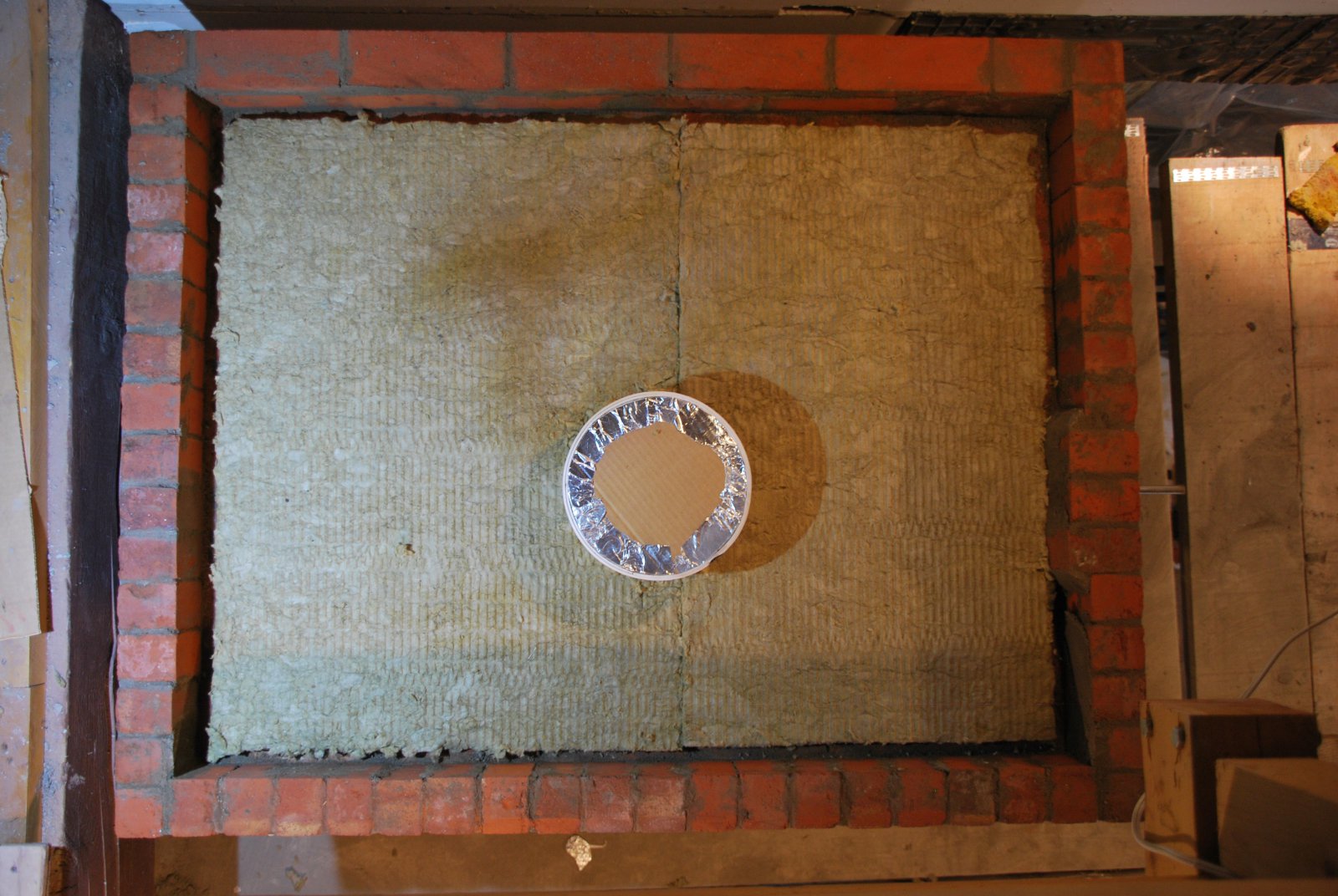
Before pouring the final common concrete slab, the capping slabs are covered with 2 inch thick of rigid rock wool. Note; The ledge around the periphery of the wool, on to with the concrete will contact.
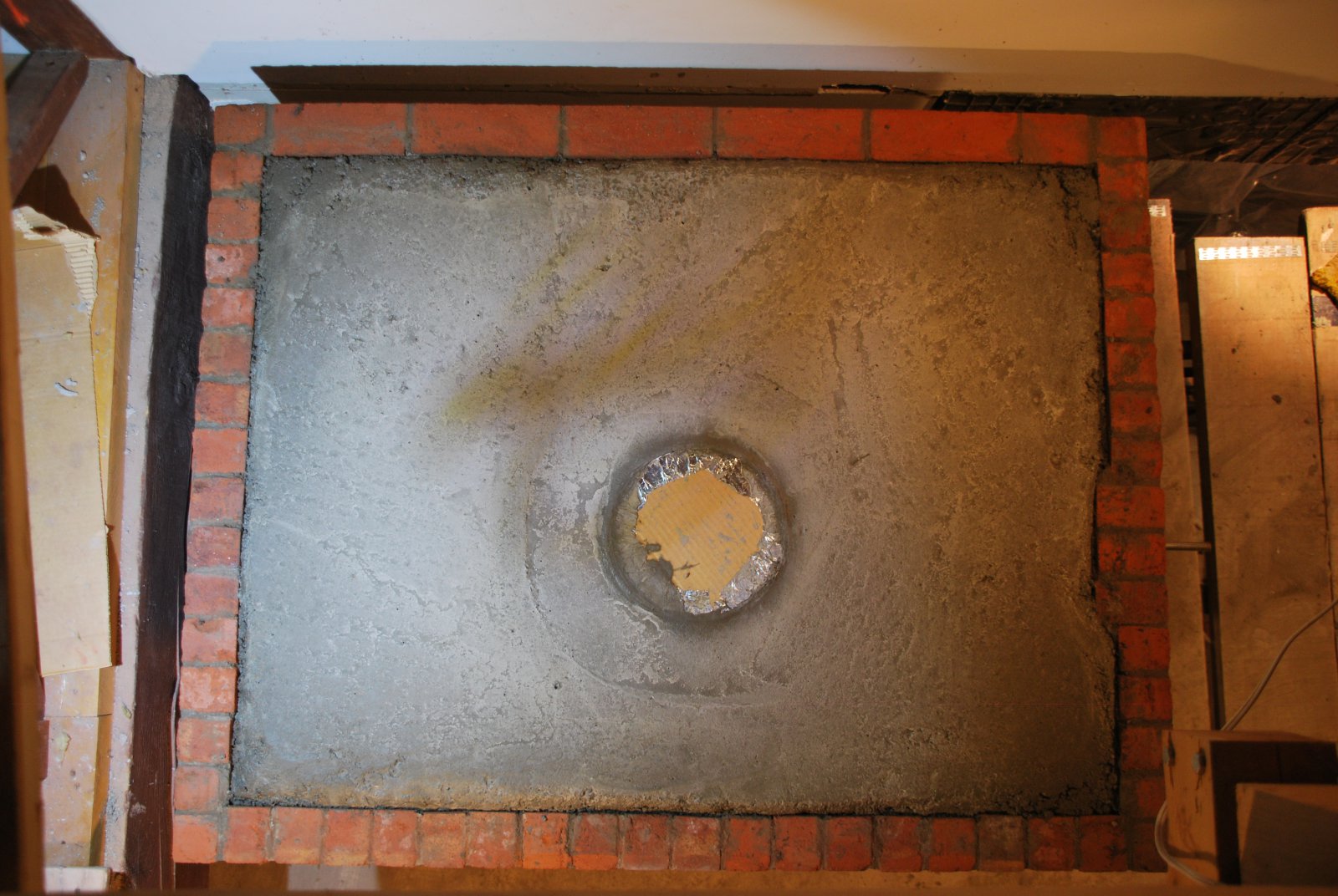
The concrete slab is poured directly onto the rigid wool. The slab is reinforced with ½ inch diameter bar.
View of the bypass and shutoff damper control levers. The damper defaults to the open position in the event the chain should slip or break. The bypass is completely superfluous and so has a square knob resembling a nut, attached to the operating rod. This will hopefully discourage passersby from attempting to operate the bypass control during a fire, while asking.. "What is this for" ...... In the event the bypass did need to be operated, it still can be, by turning the square knob.
The stove is served by an 8 inch ID prefabricated chimney by Security Chimneys.
The chimney exits from the top of the stove just right of centre, as it was required to align vertically with an existing opening in the roof.