Chimney Connection #9
This refractory core was built 4 years ago, and originally designed to have a chimney located centrally against the rear wall, connected to the rear manifold. The article Refractory Core Maine-Et Loire 2006 details the cores construction in 2006.
As an adaption of the original plan it was decided, on facing the core in 2010, to rout the gases out of each side channel, towards the chimney in a refractory brick channel running parallel to each side manifold.
The two transmission tunnels would form a bench around each side of the stove, before feeding into the chimney that would be still centered against the stove's rear wall.
The two transmission tunnels would form a bench around each side of the stove, before feeding into the chimney that would be still centered against the stove's rear wall.
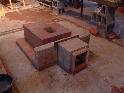
The original set up with the chimney connection through the centre of the rear manifold. Though the chimney would remain in the same place, the refractory brick connection was demolished and the opening in the manifold closed.
The core with one transmission tunnel leaving the manifold through the original access opening in the centre of the side channel wall. The enlarged access opening was used to avoid having to cut another opening further towards the front of the channel. Though using the centrally located existing access opening reduces considerably the length of active smoke path of the tunnel.
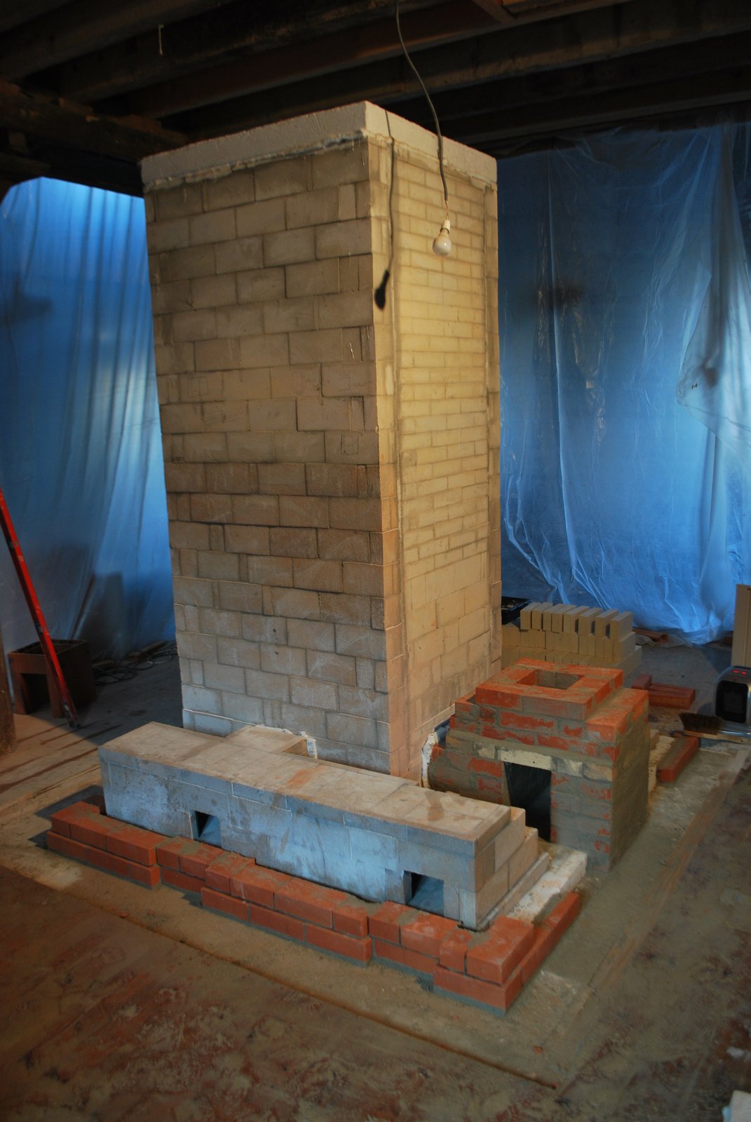
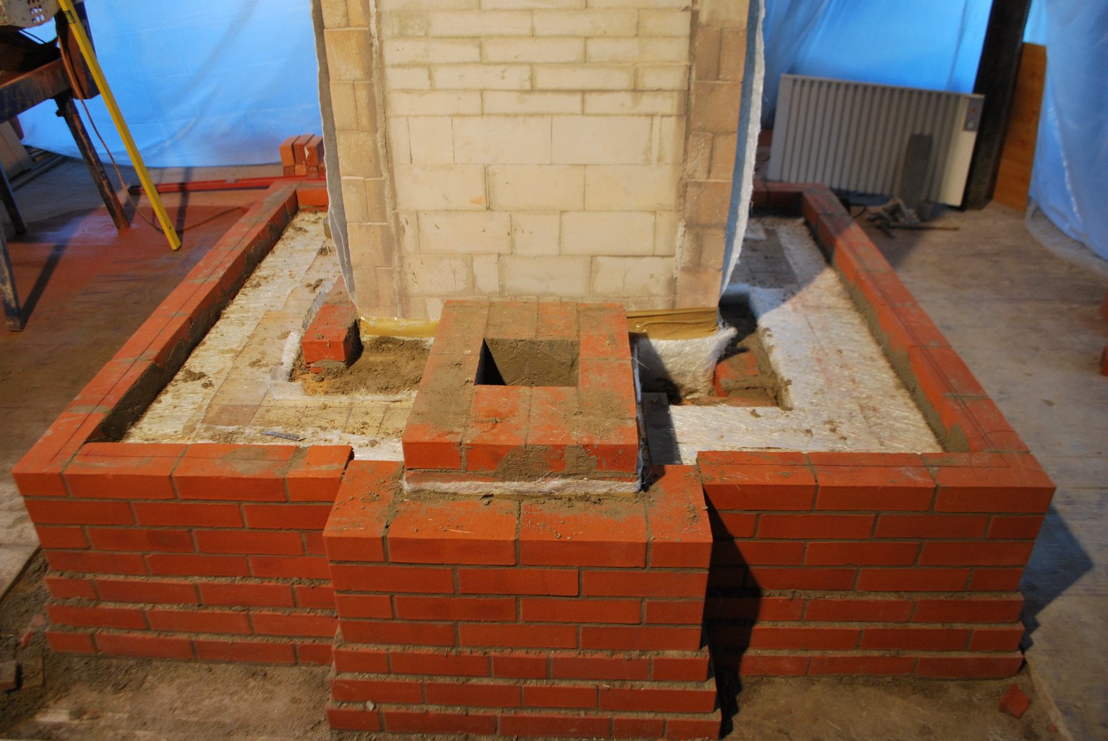
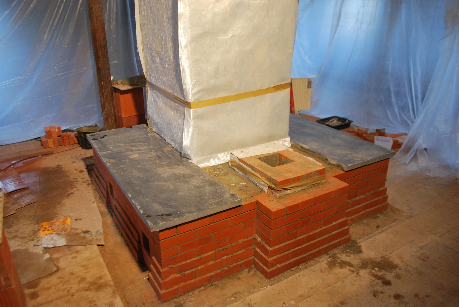
The two transmission tunnels are layed onto a bed of cellular concrete that will act as a thermal brake. The masonry pavilion that will support the chimney flue tiles though is layed directly onto the concrete foundation pad.
A tall masonry chimney exerts a considerable compressive force and should not be layed onto a thermal brake of any kind. The support pavilion has an opening on each side to accept the transmission tunnel.
A tall masonry chimney exerts a considerable compressive force and should not be layed onto a thermal brake of any kind. The support pavilion has an opening on each side to accept the transmission tunnel.
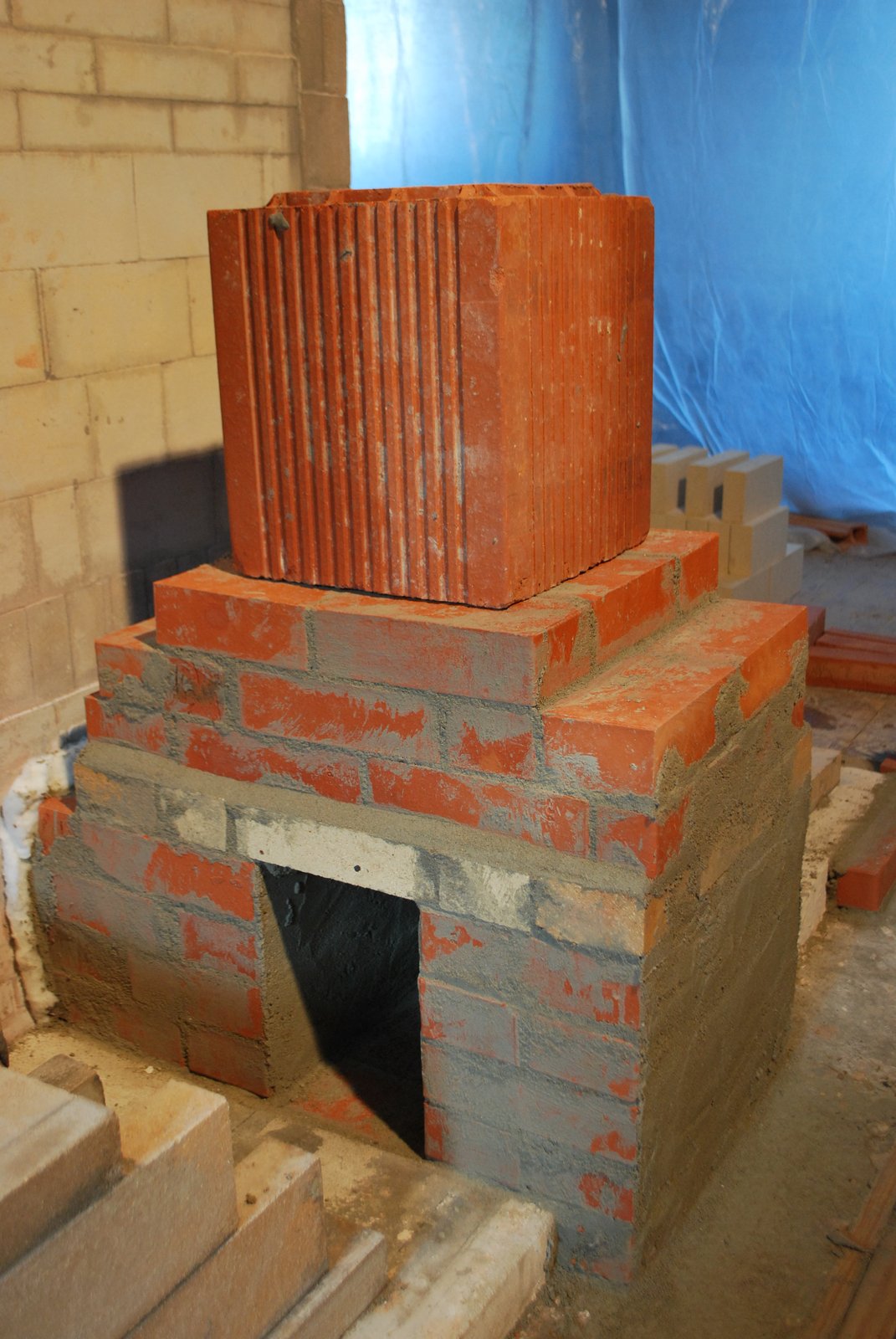
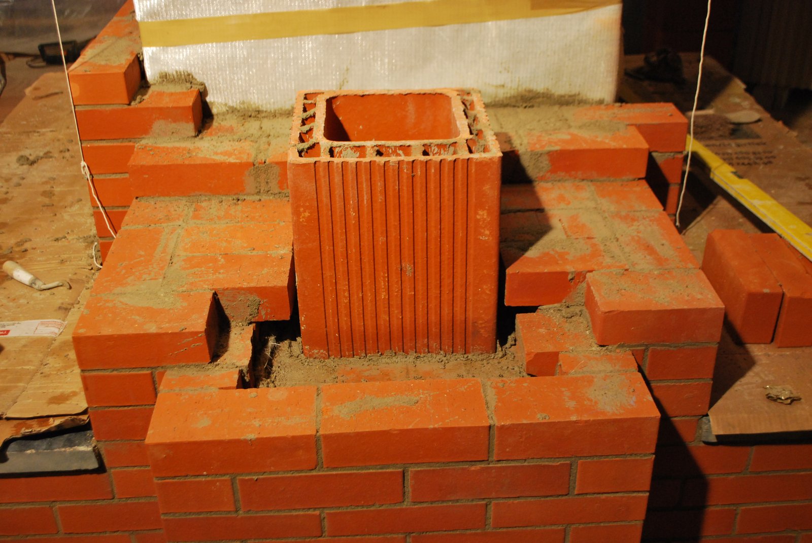
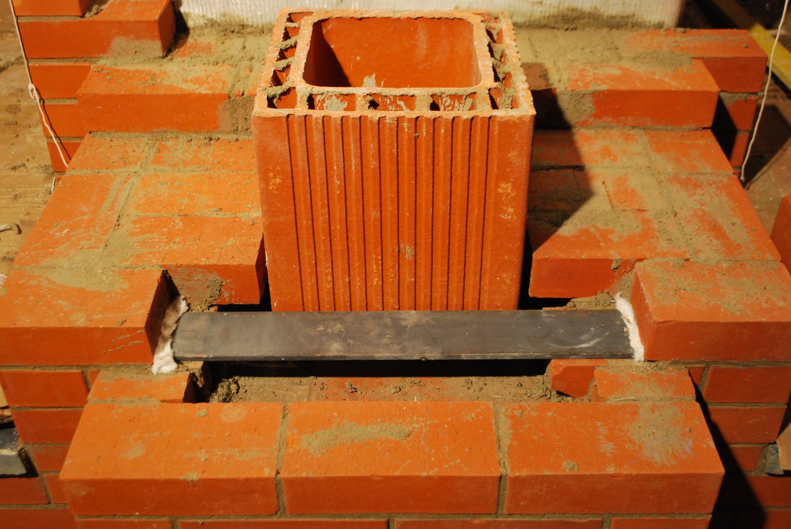
The first flue tile is in position (though in this case placed up side down by error) Building a chimney support pavilion in clay brick provides a solid support for the first flue tile to rest, and avoids having to cut two or three openings in to the first tile. As the chimney in the mill would be so tall, the compressive force, exerted upon the first flue tile would be high and so it was it was preferable that it not be weakened with cuts.
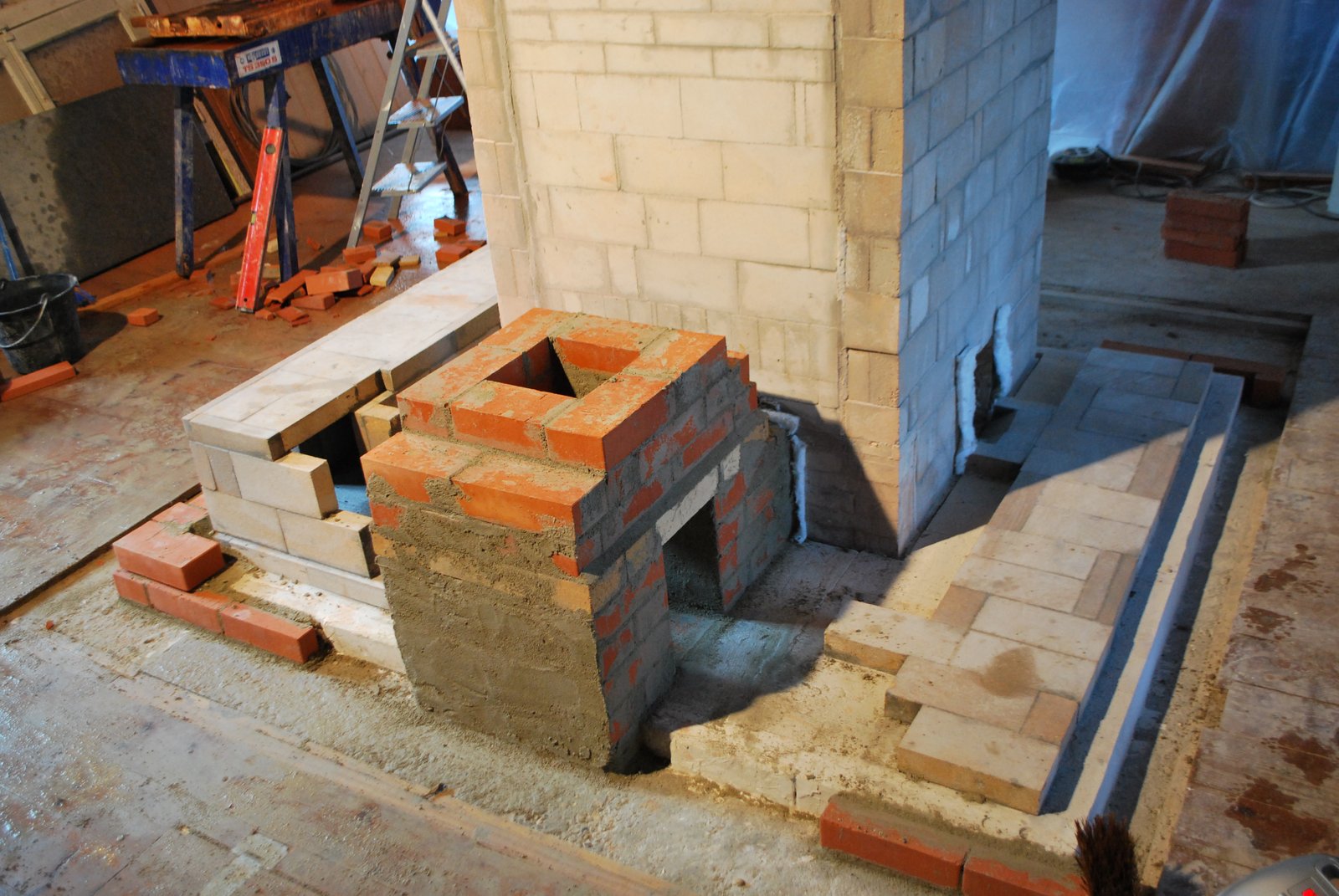
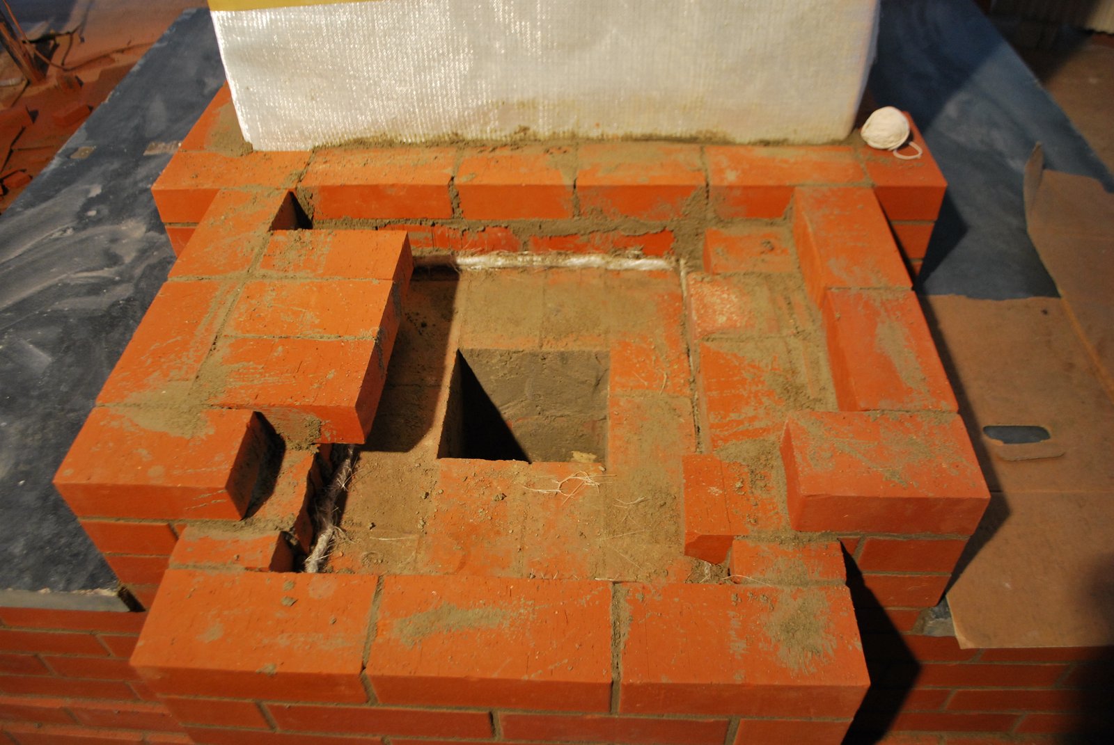
The support pavilion is built in clay brick layed in type N mortar.
Refractory brick have been used to bridge the two openings only because they were longer than the clay facing brick. The row was then finished in refractory brick to maintain the same hight. The support pavilion is layed in type N as there could be a risk of water soluble refractory mortar being weakened by dripping condensation.
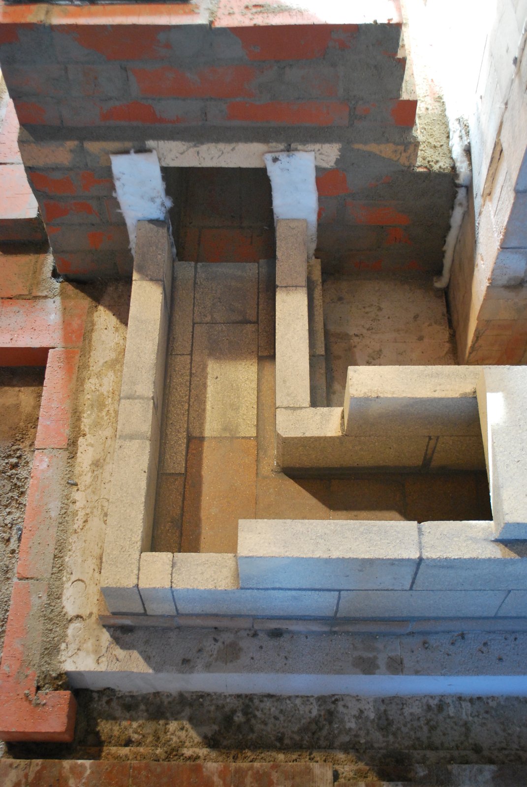
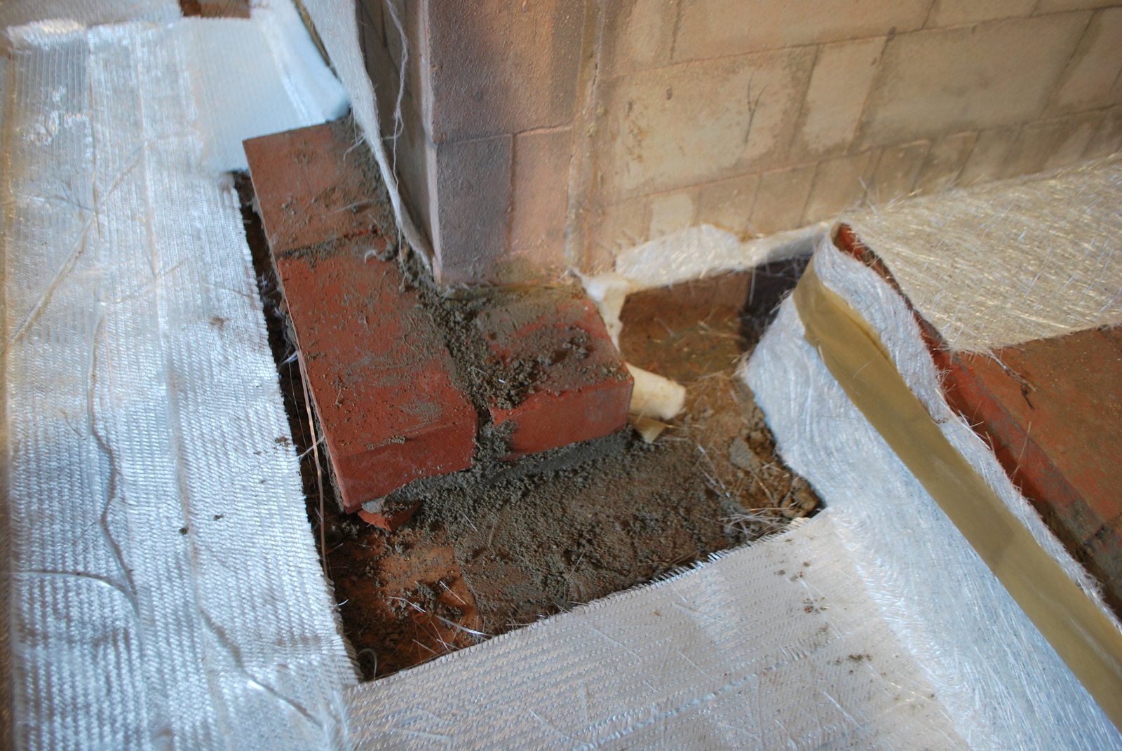
The opening in the back corner of the transmission tunnel is the chimney access opening, through which dust and debris can be removed from the base of the chimney after sweeping.
The chimney would be swept via a 7x7 inch locally fabricated access door that would be located in the bottom of the fourth flue tile. The opening being so high would enable the chimney sweep to sweep the chimney from inside the mill with out having to climb onto the roof.
The chimney would be swept via a 7x7 inch locally fabricated access door that would be located in the bottom of the fourth flue tile. The opening being so high would enable the chimney sweep to sweep the chimney from inside the mill with out having to climb onto the roof.

The transmission tunnel buts against the support pavilion with a ceramic wool gasket preventing physical contact between the two.
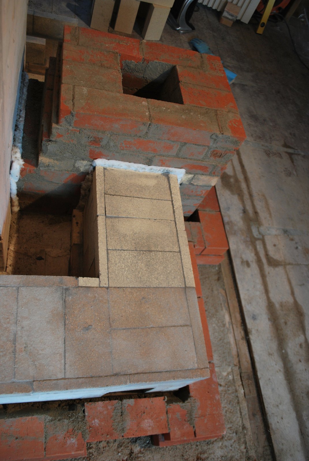
Detail
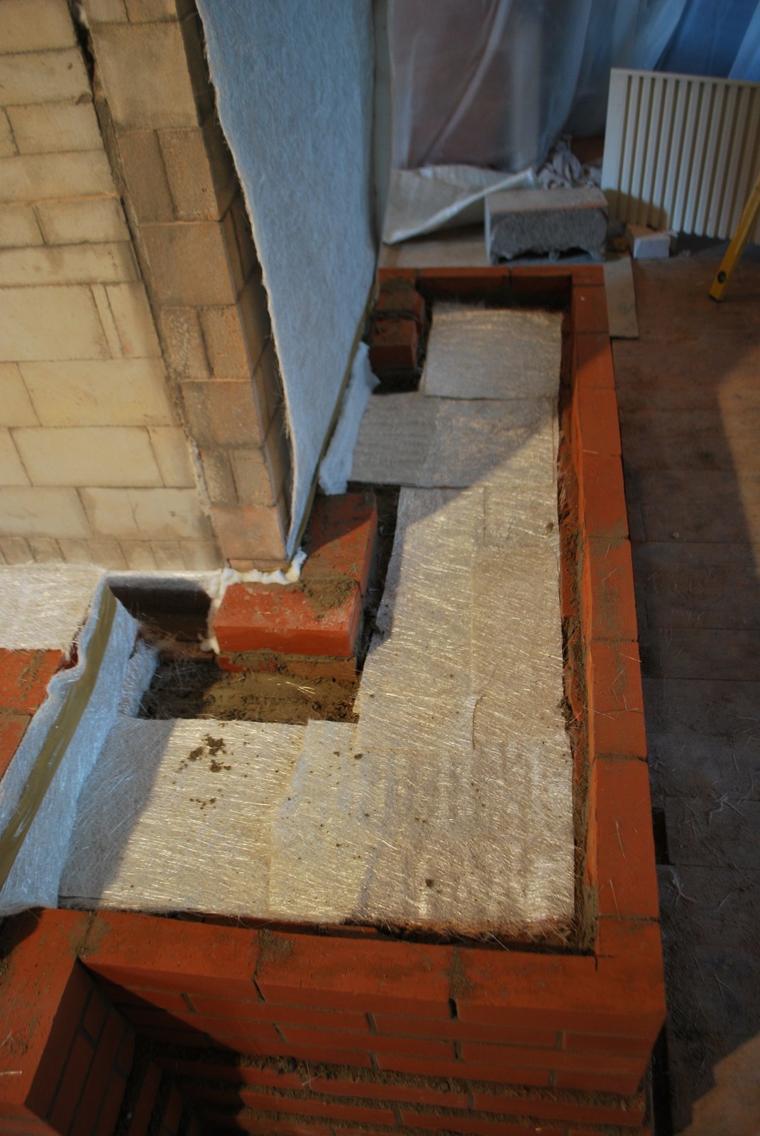
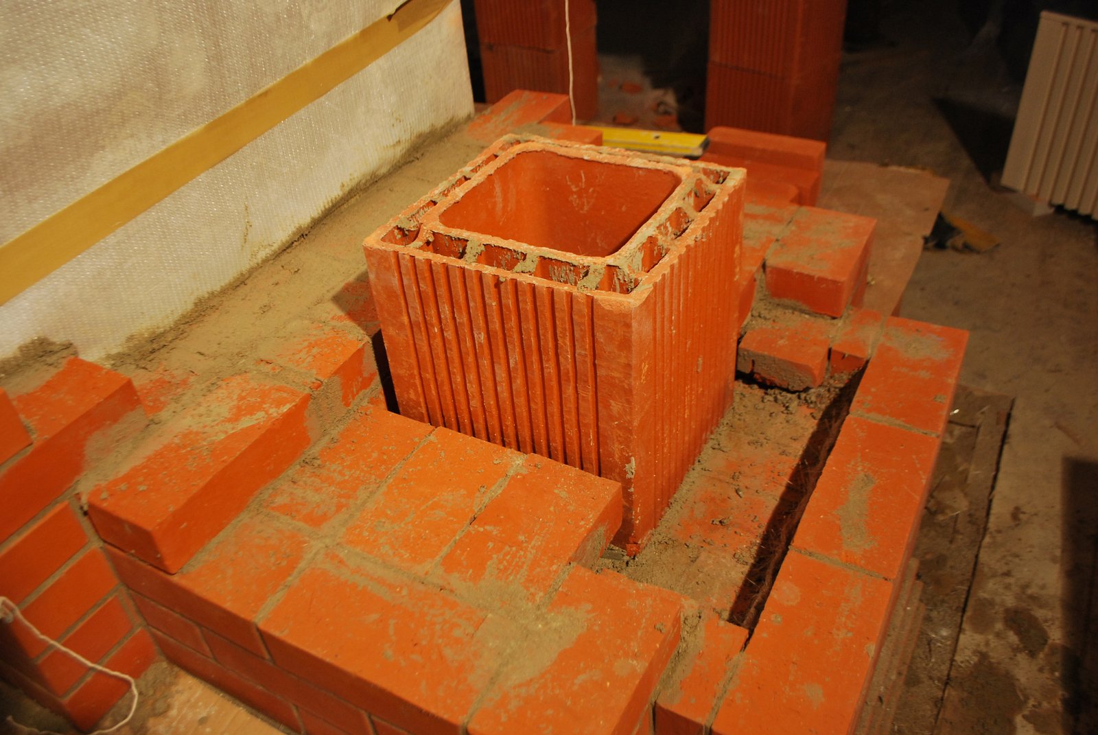
The tunnel on the opposite side of the chimney.
The tunnels are clad with 1 sheet of 450g fiber glass mat on the sides, and two at each end, before the facing is layed up. It is upon this last course of brick that the two slate slabs, that form the tunnel tops, will be layed.
The pencil line along this course of brick marks the point at which they will be cut back with the grinder. This course was inadvertently layed with full brick and so had to be cut back. They could have been cut with the saw and layed as half brick.
The pencil line along this course of brick marks the point at which they will be cut back with the grinder. This course was inadvertently layed with full brick and so had to be cut back. They could have been cut with the saw and layed as half brick.
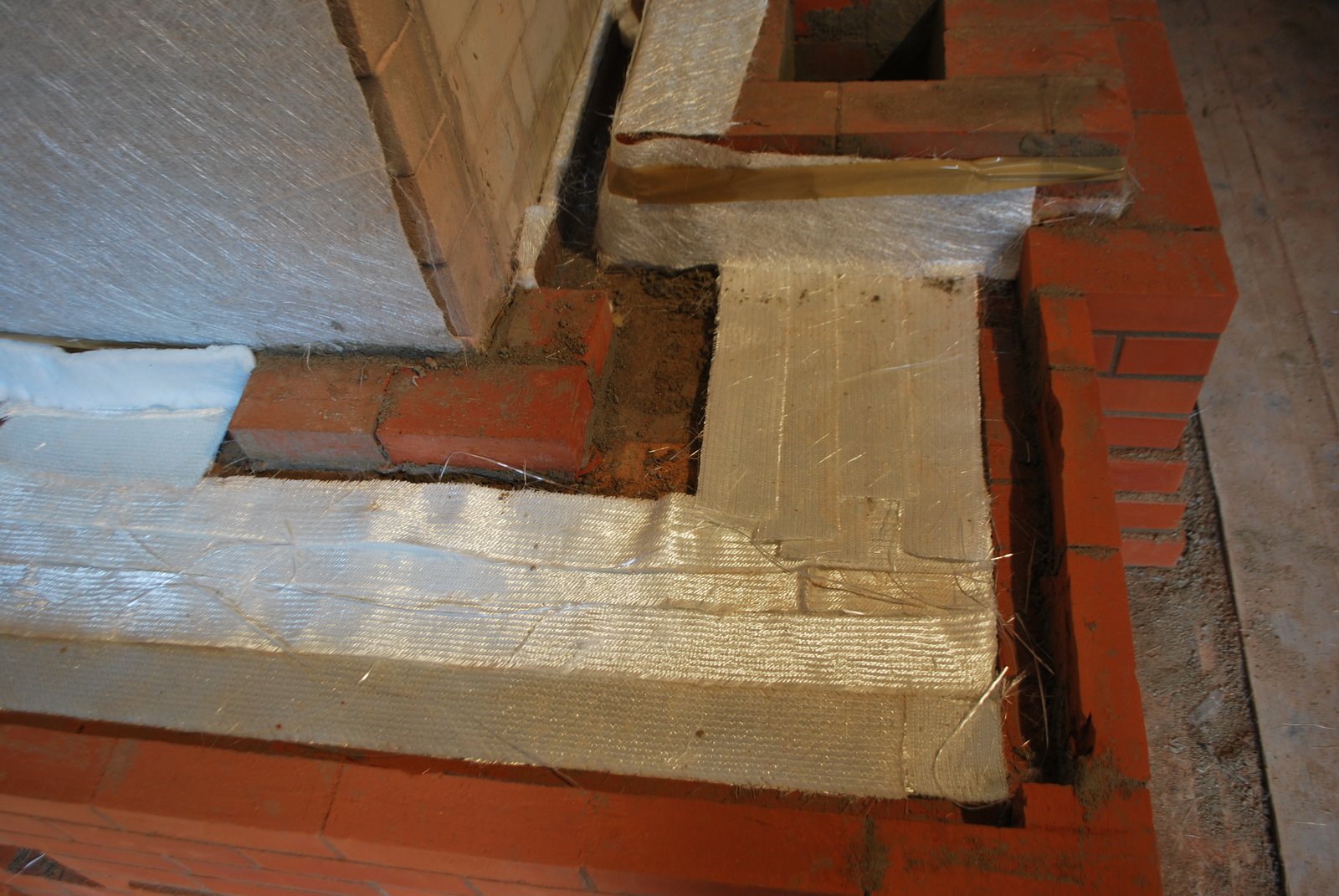
The last course has been cut back to allow the concrete, that will be poured onto the tunnel, to bridge on to the facing, at either side of the tunnel, and not on the tunnel its self. One sheet of relatively thick tightly woven mat has been used here. This kind of mat is not ideal but could be used in this situation as it was the best option available.
The tunnel leading from the right manifold.
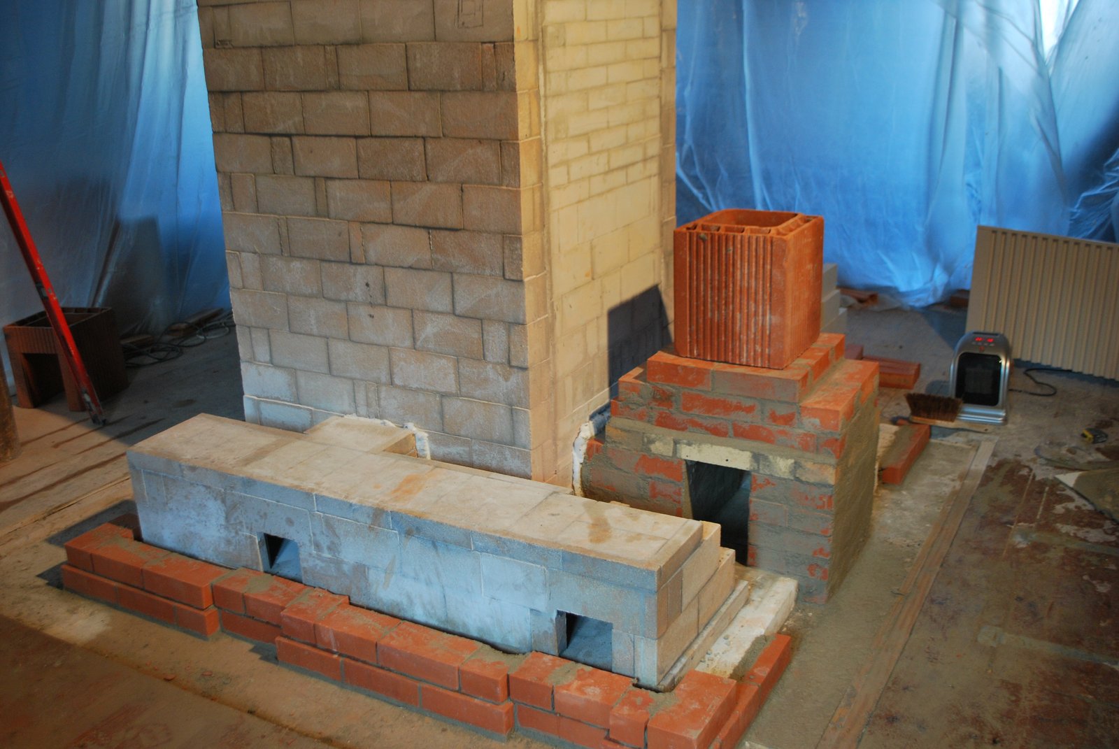
The chimney support pavilion buts up against the core and then is retracted to the actual position of the chimney, leaving space for the rear wall of the heater. The steel lintel seen here will carry the rear wall of the heater over the portion of the support pavilion that touches the core. In this way the rear wall of the heater has no mechanical contact with the chimney support pavilion.
Note that the angle iron bar is gasketed at the end.
Note that the angle iron bar is gasketed at the end.
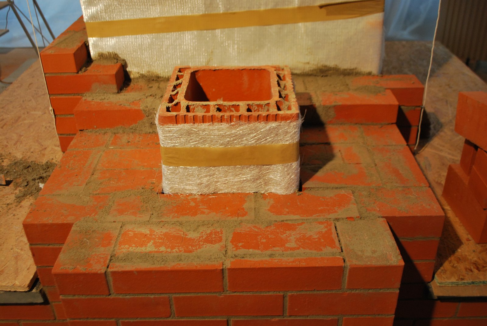
The support pavilion and the tunnels connections are surrounded by the facing, and the two slate finished surfaces of the tunnels layed. Note that the pavilion is gasketed from the facing with two sheets of glass mat. The general objective from this point is to maintain the pavilions independence from the facing as the facing is retracted from the dimensions around the pavilion to the much smaller 55x55cm dimension of the facing around the flue tile. Maybe respecting the pavilions independence is not necessary as temperatures will be low, and so expansion minimal, at this point, but the choice was made to follow the basic free floating principal of the trade.
Not respecting this and contacting the facing with the pavilion would have been considerably simpler though may have resulted in some hair-lining on the facing around the pavilion ?
Not respecting this and contacting the facing with the pavilion would have been considerably simpler though may have resulted in some hair-lining on the facing around the pavilion ?
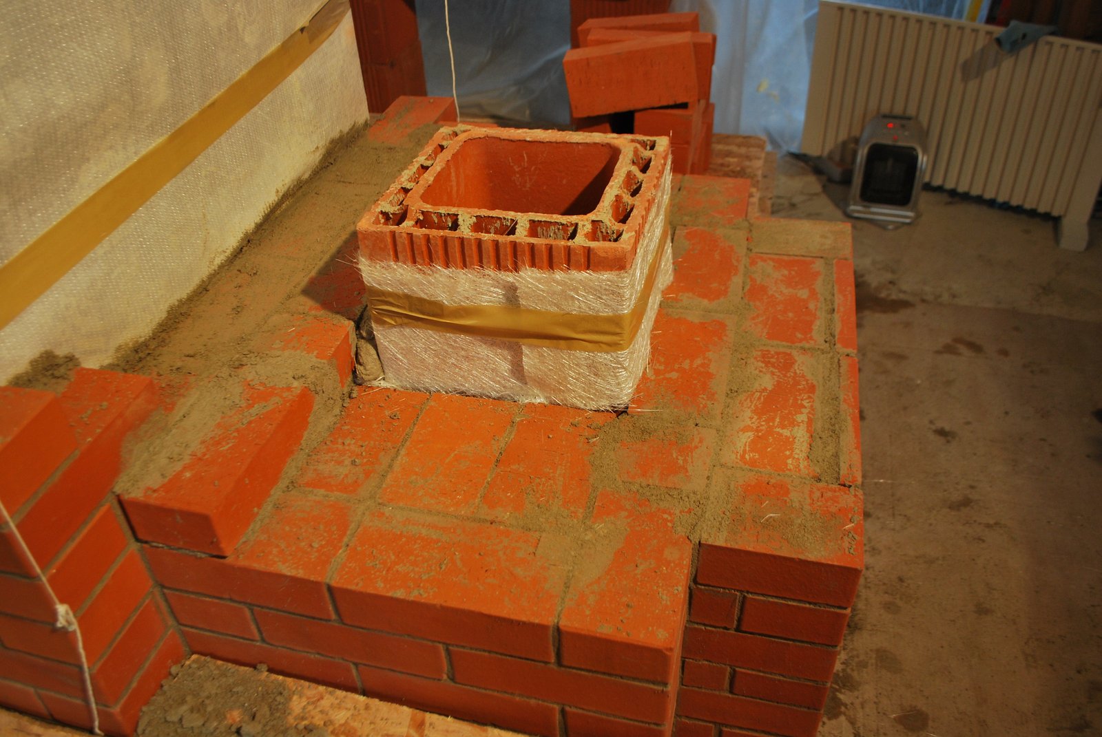
The rear facing of the chimney traverses the pavilion using a steel flat bar lintel.

The tree cantilevered brick each side of the facing will support the retracted portion of the facing around the flue tile.
The flue tile id mortared in position. Note: The tile is again inserted upside down and will be shown so in the remainder of these images. This is wrong though and before continuing the chimney the tile was broken, removed and replaced with another tile the right way up.
The front wall of the chimneys facing crosses the pavilion on a 6mm thick piece of flat bar.
Note: If the chimney were to be faced for its whole hight, using flat bar in this position would not be structurally sound. The flue tiles will only be faced in brick though for the 3 meters or so visible with the heater on the first floor. The balance of the flue tiles on the upper floor will be rendered.
Note: If the chimney were to be faced for its whole hight, using flat bar in this position would not be structurally sound. The flue tiles will only be faced in brick though for the 3 meters or so visible with the heater on the first floor. The balance of the flue tiles on the upper floor will be rendered.
The facing retracted over the pavilion, which, like the flue tile remains free floating.
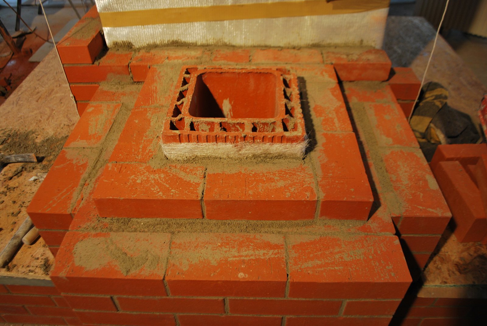
The first row of the actual retracted facing of the chimney at 55x55 cm.
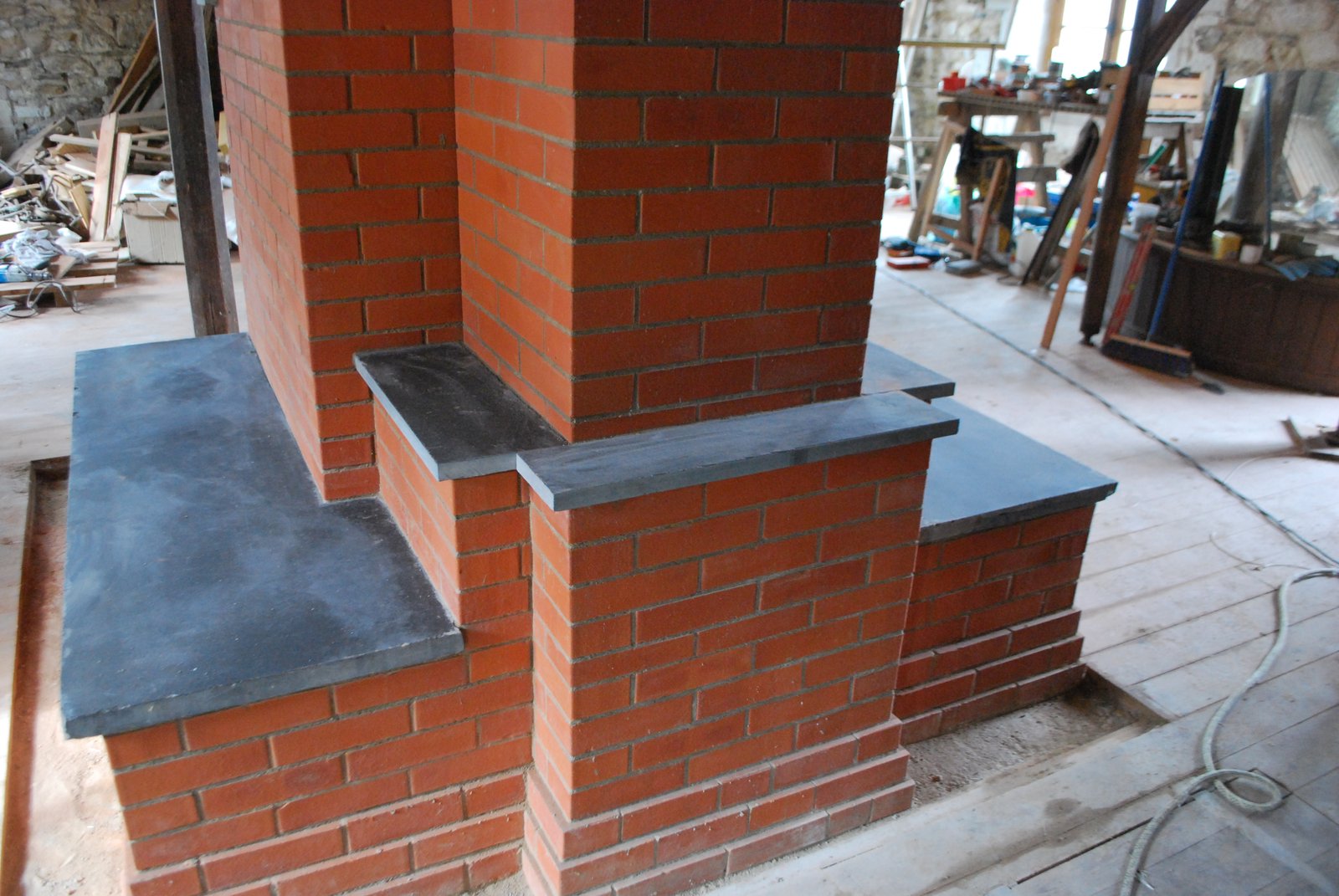
Three slate slabs cover the upper surfaces of the expanded facing around the support pavilion.
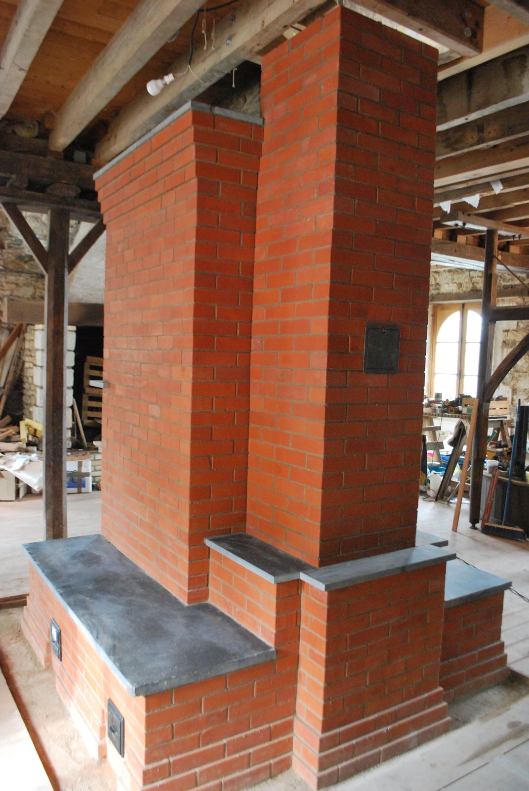
The locally fabricated clean out mid way up the rear wall of the chimney, will enable the chimney to be cleaned without the sweep having to climb the mill's roof.
Marcus Flynn
Montreal 2011
