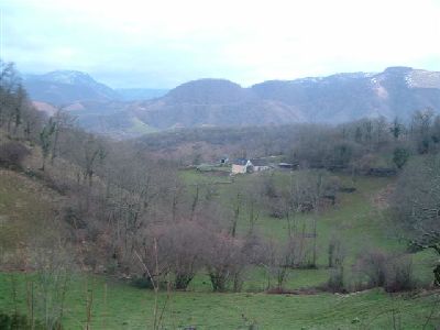
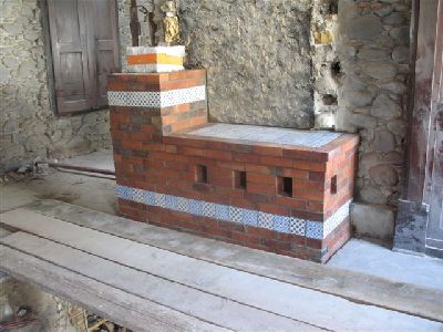
These notes illustrate certain stages in the construction of a Finnish contraflow Taaka in the Soule region of the Basque homeland.
The heater will be built into a load bearing wall that separates the building in to roughly equal halves.
There will be a fire box door on both rear and front faces of the heater. One half of the ground floor of the building will be a barbers shop, the other half, and the upper floor and attic, the dwelling of the shop owner.
The heater will be located of the site of the original stack of 4 fireplaces and their chimney, which have been entirely demolished.
The intention will be to incorporate into the heaters facing some original masonry elements of the building that have been removed by necessity during its renovation.
Materials:
Refractory Brick
Bonny B40N
Refractory Concrete
Refracol Refcast 1460 10
Ceramic Wool:
Thermal Ceramics Super wool.
Flue Tiles:
Burnt Clay 230mm diameter
Facing Brick:
DeWulf Artisanal
Mortar:
Bastard. 20% Portland 80% hydraulic Lime in a 1to3 mix
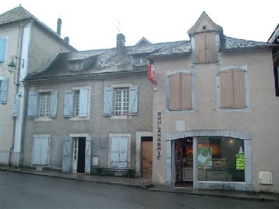
My place of abode during the project.
These two, now separate buildings were once the same infirmary. The heater will be built in the former bistro to the left of the bakery.
All constructions in the town are of rendered river rock taken from the Gave which flows 50 metres behind and parellel to the main street.
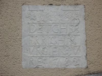
A date stone on the façade of the bakery bears a now unintelligible inscription in Basque and the date, of either construction or the separation of the the two portions of the original building.
Most of the foundations in the neighbourhood are from the 16th century.
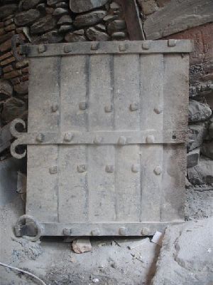
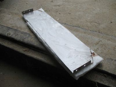
An iron fire back, used to protect the masonry wall behind the fire in the largest of the original fire places.
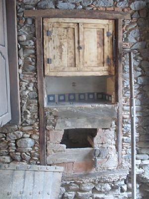
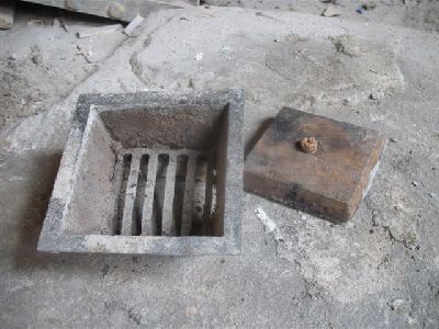
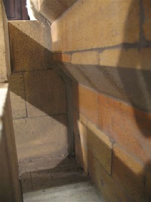
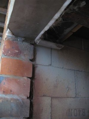
This dish warmer is built into the original passageway between the two sections of the building.
Embers would be put into a recessed grate to the left of the tiled platform, and plates of food placed on top of the grate to stay warm. The ash from the embers would fall through the grate into the void below. The opening to this void, according to a man born and raised in the house, was once fitted with a steel door.
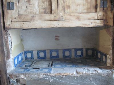
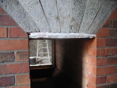
The masonry, below the platform and around the opening, was originally rendered.
Detail of the tiled platform. The recessed grate to the left is seen closed with a wooden cover. Some of the tiles removed from the plate warmer would be used in the façade of the heater.
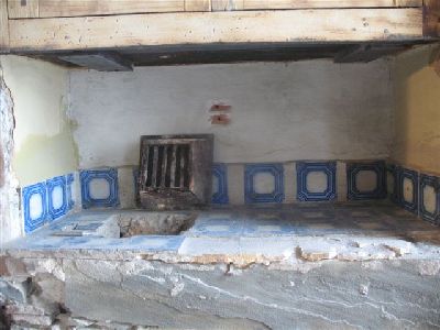
The cast iron grate can be lifted out of its housing.
This appliance had no avaloire, but in a house filled with fumes from 4 smoking fire places, the gasses from the embers in the grate would be unnoticeable.
Even today people in French villages can be found happily sitting in rooms full of smoke.
The grate and wooden couver plate.
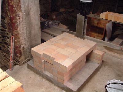
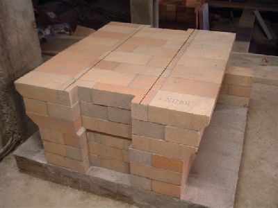
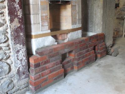
The first 5 courses of the core are layed onto a course of common brick, which is layed onto a course of Ytong cellular concrete, that acts as a thermal brake.
Cellular concrete is not layed beneath the chimney as its compressive resistance is less than the possible focused compressive force of the 11m. high masonry chimney.
The finished floor will be 8 cm higher than the concrete footing.
As there is no basement, and so no possibility of an ash drop, a grate would be superfluous Ashes will be removed directly from the fire box floor by shovel.
An additional 6th row of refractory brick have been added to the firebox floor to account for a miscalculation during mark out.
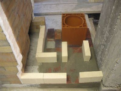
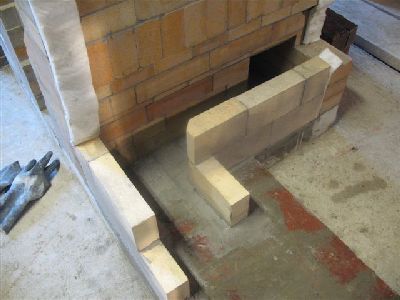
The final course forming the fire box floor is layed so that every brick will be physically held in place by the sloped first course of the fire box walls. The pencil lines indicate the interior line of this first course of the walls.
Note the cut outs for the two primary air channels.
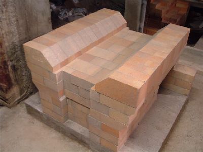
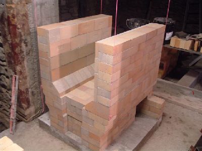
The first course of the fire box walls.
The fire box walls before being lined with splits.
View of the manifold showing the compensation made necessary by the original miscalculation. This will not effect the heaters performance, but takes more time and materials, and raises the overall hight of the heater by one course.
Splits or as in this case, brick sawn in two can be used to line the fire box.
Note: In a see through the fire box temperatures are way lower than with a conventional fire box, making the liner virtually superfluous. Temperatures in the upper areas of the core though are comparatively more intense than with the standard five box.
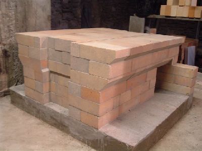
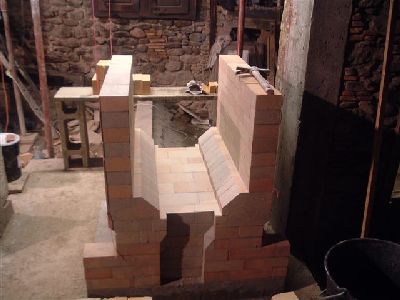
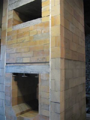
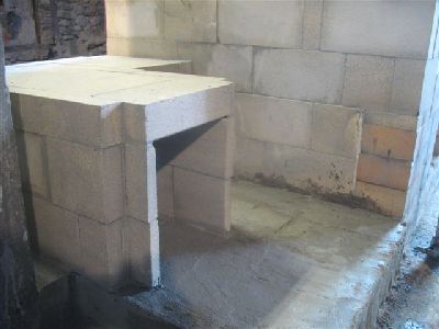
The core before installation of the side chanels and capping slabs.
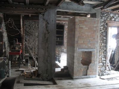
Seen from the shop.
The core before installation of the channels, seen from the kitchen.
Note the stone support arm for the avaloire of the original fire place, to the left of the core.
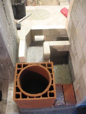
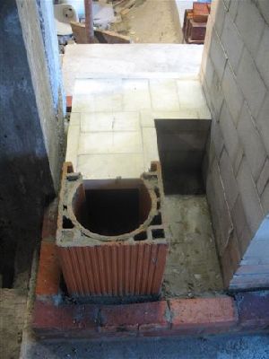
The dry lay out of the chimney conection from the manifold into a 320mm diameter clay flue tile.
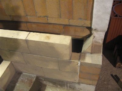
The first two courses of the side chanel and chimney conection.
TView in side the manifold showing the cerramic wool gasket parged with HTC.
The side channel as it meets the rear manifold wall.
The connection opening in the side channel is spanned by a single brick which bridges for only 1cm on each side wall.
The lower portions of the side channels were built with a slightly smaller locally acquired brick, as not enough B40N were ordered.
Even common clay brick if layed in HTC. are suitable for building the lower portions of the side channels. These local refractory brick have an aluminium content of 22 % as opposed to the B40N s 40%
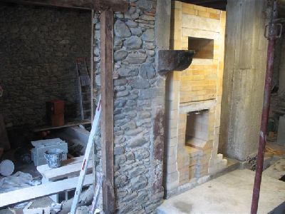
The finished core from the kitchen.
The flue tile is placed exactly in position, before being marked and cut.
The end of the transmission tunnel that is cut to feed into the flue tile.
The end faces of the tunnel walls are gasketed with ceramic wool.
The flue tile is layed in place with common mortar.
This tunnel provides an extension of the smoke path and slightly easier connection to the flue tile.
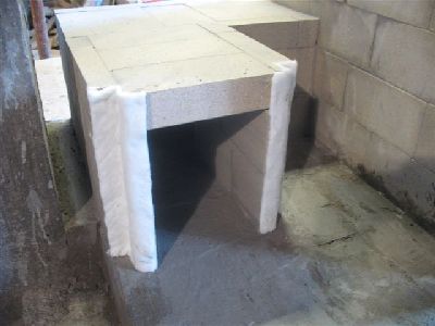
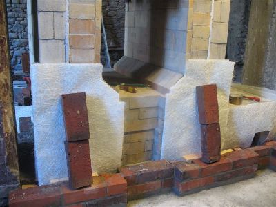
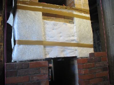
The first layers of fibreglass mat are held in place by brick before being taped to the core. There are 4 leaves of 450g glass mat, front and rear of the core. At this point there is no glass mat used on the side faces of the channels, though the mat used on the front and rear wraps around the corners of the channel walls.
The glass fibre mat sheets are held in place by tape and the backfill of the space behind the brick, between the rear face of the brick and the gasket.
Note the gasket covers the corners of the channel walls.
The top of the transmission tunnel is finished with an old paving stone.
The facing brick are artisanally made by Dewulf of Allonne. They are burnt in the last wood fired Hoffman brick oven in France.
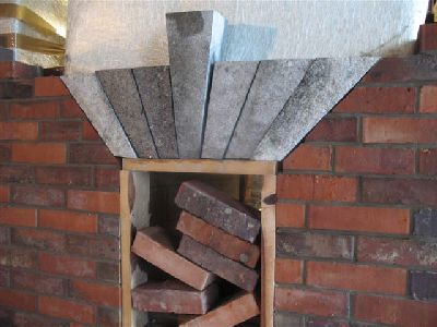
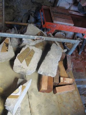
The three arches of the heater would be made from Arudy Marble, the source of which would be several old stone lintels. This marble takes its name from its point of extraction in the village of Arudy, about 25 km from the site.
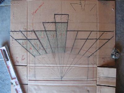
As long as accuracy is assured at this stage of the arches construction, all other problems arising during assembly can be corrected, or compensated for.
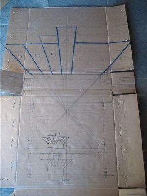
The same cardboard template would be used for both fire box arches.
Sometimes the boxes in which the doors come, can be the only source of cardboard for these templates.
The portion of the core behind the arch is insulated with a sheet of ceramic wool. This has been done only over the opening on the kitchen side, the shop side having only four leaves of glass mat behind the arch. The oven opening in the kitchen causes an added weakness to the facing on that side, and the wool is intended to even out transfer from the core into the arch and surrounding facing.
The arches key and voussoir ready for assembly.
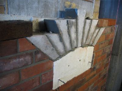
The arch is dry layed in position.
On the Shop side.
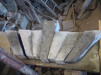
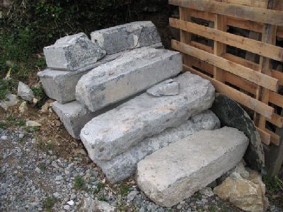
The ancient lintels and steps from which the arches were cut.
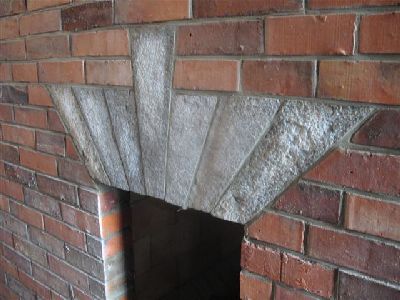
The vousoir for the arch were cut to preserve the original boucharded texture of the stone .
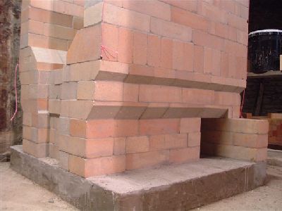
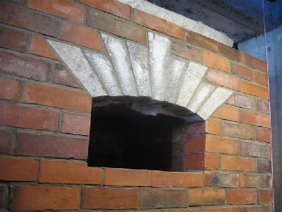
The completed arch on the shop side of the stove.
The assembled arch on the kitchen side of the stove
A heat shield to protect the vousoirs was adapted so that it could be screwed into the skew backs rather than directly into the vouisoir them selves. Arudy Marble is relatively fragile and so it was better to drill in to the brick than chance splitting the stone.
The corners of the stainless steel shield are cut back so that the small portion that contains the screw holes, bent perpendicular to the shield, does not restrict the expansion space on each side of the inner flange of the door frame.
Two pieces of wool are held in position and protected by the 22 gage stainless steel plate.
The cardboard template for the oven arch.
The stone stock is sawn and cracked to provide a format from which the voussoir can be cut.
The templates for the individual voussoir are layed out on to the available stone, before starting to cut.
The oven arch layed over a support cut from two sheets of expanded polystyrene.
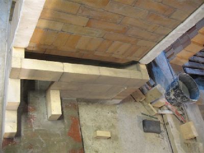
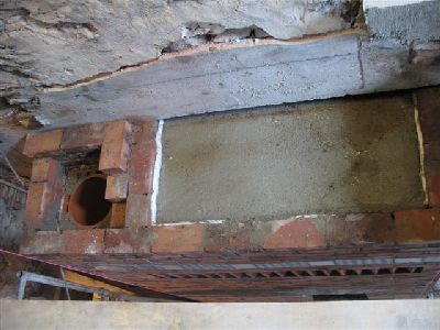
View of the common concrete capping slab from the shop side. The space of 3cm between the slab and the lintel over the original opening, allows heat from the portion of the slab that lies beneath and beyond the lintel to thermo-syphon out and up to the dwelling on the first floor. This space also allows ample room for vertical expansion of the core which will be approx 3-4 mm
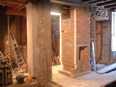
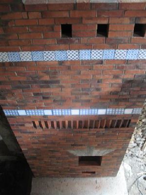
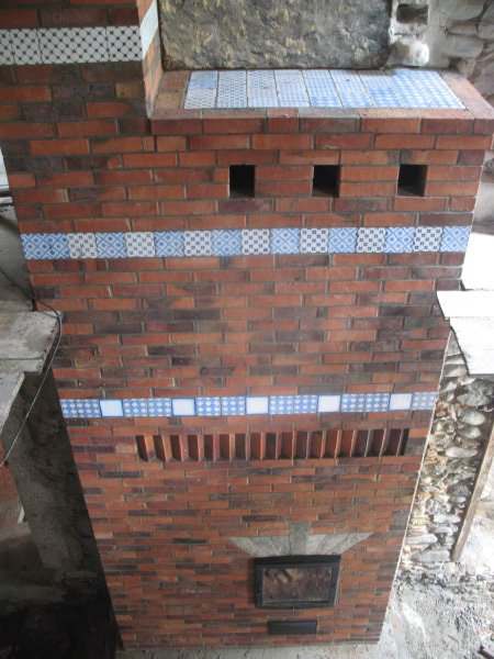
Seen here with the first floor removed: the facing of the stove in the shop has been continued up into what will be the living room on the first floor.
The portion of the facing that continues onto the first floor.
This will allow heat to thermo-syphon directly of the entire upper surface of the capping slab, in to the otherwise closed living room above the shop.
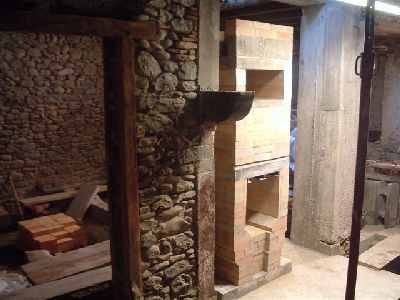
The chimney will be continued by a local mason.
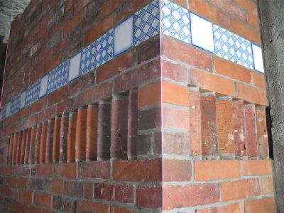
The tile were layed in common mortar with little or no head joints
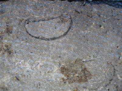
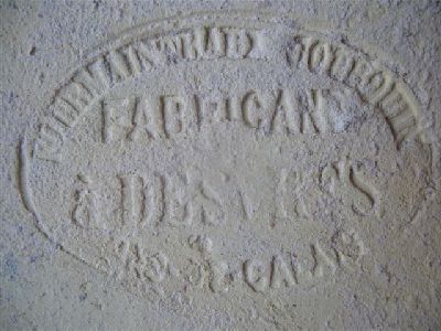
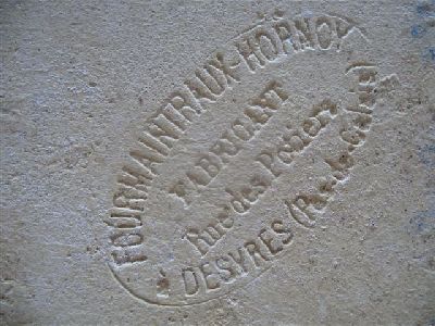
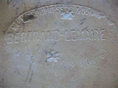
The following three images show the manufacturers stamp on the rear surface of the tiles used in the facing.
The tiles were made in the late19th and the early 20th century. Some were recuperated from the buildings original kitchen, though most were bought at auction.
See also Porfolio