
January 15/09
January 17/09
January 18/09
January 20/09
February 5/09
March 8/09
March 14/09
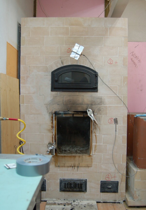
Temperature sensor locations
Sensor 1 is at position 1, insulated to the exterior, to avoid hot air effects from the doors.
Sensor 2 is at position 3, uninsulated
Spreadsheet data for graph, below:
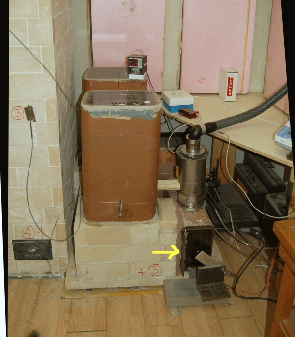
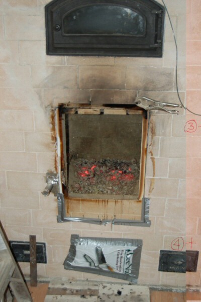
We decided to change the existing experimental bell setup. The yellow arrow points to the sliding
flue damper.
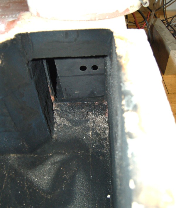
Oops. With the bells off, this is the sliding damper in the "closed" position for tests
HK-K01 to HK-K09. So the "closed" surface temperature curves (above), are not really
valid, and need to be redone. At least we caught the error.
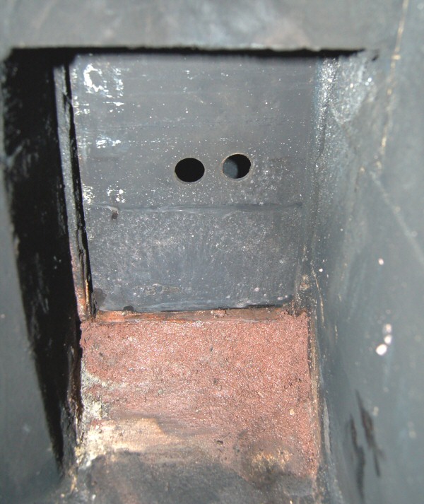
Damper plate was refitted, and now closes to within about 1/8". The two 1" leakage holes will
be taped up for the subsequent tests.
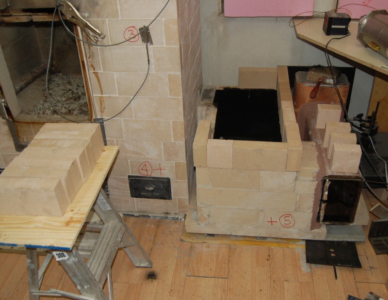
Setup for the new bell.
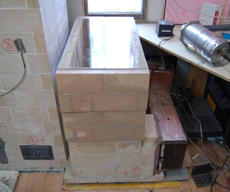
New bell, phase I. It is 5 courses high (22.5"). We'll get some data with this configuration, and then build it higher to see what further
effect there is on flue temperature, etc.
Surface temperatures.
Surprisingly, the leak in the damper did not have that great an effect.
Damper is left open on test HK-K11.
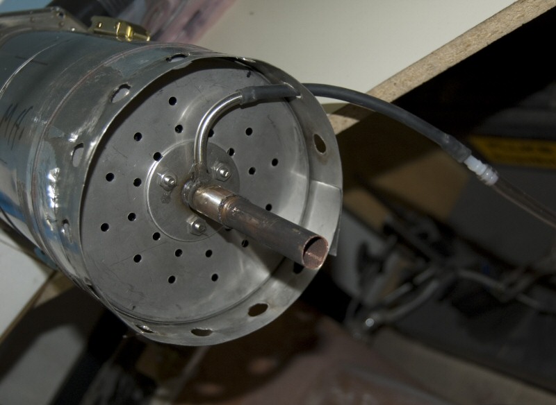
The Condar has a skirt added to provide some separation between the dilution holes and the flue liner. The 3/8" very short nozzle on
the Condar had been extended with 1/2" copper, in order to reach the center line of the flue.
Here it has been shortened by 2" to reduce possible friction effects.
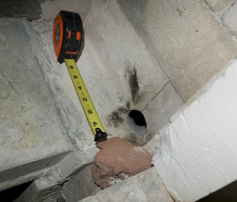
The test series was interupted for 12 days. While the heater was cold, the cold air bypass has been enlarged.
A pitot tube has been installed in the centreline of the flue, to allow a rough estimate of volume flow rates in the chimney under
various damper scenarios.
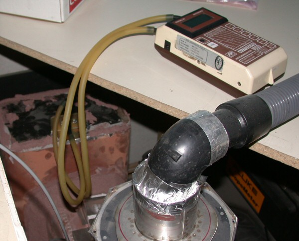
Pitot tube is connected to a digital micromanometer for pressure readings.
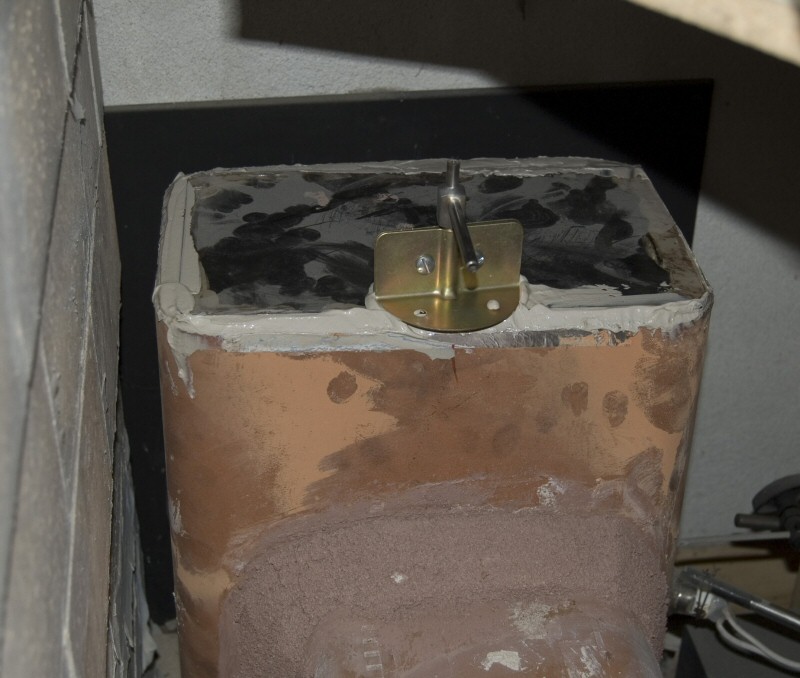
View of heater top, showing top of vermiculite concrete, no facing on rear of core, sheet metal
seal for core, 3" air space, sheet metal heat shield spaced 1" off stucco wall.
Temperature probe measures front surface of the heater shield.
4 channels of temperature, as described in the legend on the graph. Multiply temperature axis by 100 (see graph below)
Starting from a cold start on Feb 2/09 (HK-K13)
On the second run, the flue damper was left open, with the cold air bypass open
On the third run, the flue damper was left open with the cold air bypass closed
On the fourth run, the flue damper was left open, and the ashbox door was left open (reference for worst case scenario)
Close up. The pink curve tracks temperature on the top of the bare 8x12 clay liner leading to the metal chimney.
Note the quick drop when the chimney damper is closed. Compare with second run, when damper is left open.
Note on the heat shield curve that the air stream picks up fast temperature changes in the small, well insulated
test room when the door to the adjoining production shop is left open or closed, or partly open for an extended period.
With the door closed, the room gets above 100F. Note that some of the surface temperature readings track the
room temperature changes. The green line shows a new probe on the side channel. After this run, the probe
was insulated to the room. Note the higher peak on the second run, relative to the probe above the bake oven
(position #1).
This graph shows the exit flue liner temperature. The red line is with the air wide open.
Note that the flue liner is initially hotter, as the stored heat is bled from the heater. 24 hours later, it is colder,
as the stored heat has been used up to power the chimney. Damper was left open in both cases.
You can calculate the radiant heat output of a surface directly. In the graph above, the area under the curve is related
to the heat output. By counting the squares under the graph, you can compare the heat output of the surface over 24 hours
with the air supply open and closed. In both cases, the flue damper was left open.
A more accurate representation would be to graph the 4th power of the absolute temperature
(Fahrenheit + 459), which is directly proportional to the radiant heat output.
For the above statements to be valid, you would also need to account for the radiant heat INPUT to the heater.
The test heater is located in a small insulated room (a calorimeter room). Therefore, most of the cooling
results directly or indirectly from air flows through the lab. door, assuming it is left open. With the lab. door closed, the
heater will cool very slowly. This makes the above-proposed method unuseable as-is, for comparing heating outputs from two runs,
via surface temperature measurements alone.

The above graph shows a single burn in a cold heater, with the laboratory doors left closed. The heater takes about 5 days to come into equilibrium with the room.
The blue line at the bottom tracks the outside air temperature. Notice that it was cold, and warmed up considerably on March 5, in the morning.
An extra sensor has now been added to also track the shop air temperature, which contacts 3 of the 6 calorimeter room surfaces.
Note the little bumps in the temperature decay curves, that are tracking the outside temperature. The floor of the room is insulated to R-10, and the walls and ceilings to R-20.
The goal now is to generate further data, that will allow a calibration function to be established for the calorimeter room, based on outside temperatures.
Then, the room should be useable directly to measure heat output, by running a stream of air throug the room, whose in/out flow rates and temperatures are known.
Same scale as above, burning a smaller load of wood, 34.4 lbs from a cold start. Note outside temperatures are warmer.
Heater takes about 4 days to cool down.
This page was updated on
March 14, 2009
This page was created on January 15, 2009