In Russia, most residential buildings are heated by hot water supplied centrally by municipal boiler stations. The country currently experiences crisis of such municipal systems and networks. Existing municipal boilers are inefficient, burn expensive fossil fuels and very often are in use much longer than their normal life expectancy. Due to chronic deficit of municipal budgets, no repairs or upgrades were done to the equipment for many years. In a situation where every saved penny counts, it would be highly beneficial to switch into a cheaper fuel available locally, and to create new high efficiency boilers.
At the same time, there is a trend to replace central heating networks with autonomous individual heating systems that burn local fuel from renewable sources. Many countries have programs aimed to increase use of renewable fuels. A need for new heating systems arises. Such systems should burn fuel from renewable energy sources. They also should be flexible enough to be easily modified to suit different requirements. Such systems should be able to supply heat for individual or multiple buildings, and to serve other purposes.
Our system for design of masonry stoves and boilers corresponds to these requirements at full extent and offers unlimited opportunities.
In this article, we discuss design of wood-burning masonry boilers (further: "boilers") that burn wood. What characteristics should such boiler posses? What it should do?
Boilers for individual residential buildings should be able to supply required amount of heat and retain required temperature for 24 hours with two one- or two-hour firings a day (periodic action boilers). They should also have a back-up energy source to maintain temperature in the system and in the house above freezing when the owner is away. There is also demand for constant action boilers (constantly fired) that are suitable for use in central municipal systems or for central heating of large residential/industrial buildings.
If one would pour hot water into a glass and put a spoon in it, water will start to give its heat to walls of the glass and to the spoon till their temperatures equalize. If one would turn the glass upside down and fill it with a hot gas, heat exchange here would follow the same pattern. In both cases, heat loss is minimal. Efficiency of such system is 93.7%. Such bell can have any shape and volume. If one would do a horizontal cross section of the bell, any point of the cross section will have the same temperature. Temperature will be higher in each ascendant cross section. With continuos supply of heat energy into the bell, movement of the hot gases inside the bell happens due to the force of gravity (hot gases rise up, cool gases come down) without aid of any external force. In traditional boilers, such external force is draft created either by a chimney or by a fan. Convective system of all our boilers is designed by this principle. Our boiler consists of a firebox (A) and a convective system (B). Convective system can be in form of one bell or two bells one upon another. The lower bell is designed by the formula: "the stove's lower level and the firebox are combined to form a single space creating a lower bell" (dry joint is a necessary condition). Only such design of the lower bell give us an opportunity to meet all requirements that are listed at the beginning of the article. Boilers built according to our system possess several unique features not inherent to boilers of other systems.
Let’s regard the difference between combustion of fuel in traditional boilers (with forced gas movement) and in boilers built according to our system. We can imagine the process of fuel combustion. The air flows over the red –hot surface of the piece, wherein the oxygen atoms combine with carbon atoms on this surface turning partially into carbon dioxide (carbonic gas) and partially into carbon oxide. During combustion process a piece of fuel is getting smaller in size and after combustion there remains incombustible ash. Inflammable gases consisting of carbon and hydrogen (hydrocarbons) burn over a piece of fuel. Hydrogen being lighter, burns a little bit quicker than carbon, it combines with oxygen quicker and during combustion turns into steam. Carbon until complete combustion is in the flame in the form of soot dust. These specks of dust get heated from the neighboring already burned ones to become fluorescent, and when they react with air they burn. So one can say that the flame in itself is the burning hydrocarbons. The burned carbon-soot turns into carbon dioxide (or into carbon oxide in case of incomplete combustion). So over the flame we see there is something which is left after combustion, i.e. carbon dioxide (and carbon oxide, in case of incomplete combustion), steam and nitrogen. Besides, there may be a certain amount of oxygen, not having been burned during combustion, and steam which appears during evaporation of water present in fuel. All these gases do not take part in the combustion process, they only get heated due to the heat accumulated during combustion of carbon and hydrogen. Let’s call them ballast gases as they do not take part in combustion and require energy to be heated. The molecules of all the gases named are totally independent, they are not interconnected. Hence the hot gases, or the so-called products of combustion, coming from the firebox represent a simple mixture of several gases. In systems with forced gas movement the complete flow including ballast gases goes through the firebox and convective system decreasing the temperature in them.

In the systems built according to the formula "the stove's lower level and the firebox are combined to form a single space creating a lower bell" the combustion takes place in a different way. The particles of inflammable gases (hydrocarbons) combine with oxygen of the air and produce heat to turn into carbon dioxide (in case of incomplete combustion – into carbon oxide) and steam from the burning of hydrogen. They have a higher temperature than the temperature of the steam of fuel, nitrogen as well as oxygen that has not reacted (excess air) and therefore come to the upper part of the bell thus creating an increased temperature zone. The fuel steam, nitrogen and excess oxygen (air) and gases, which gave off heat, come down to the lower part of the bell. In this case we may speak not only about separation of hot and cold gas flows but also about separation of the gas flow (a mixture of several gases) into components. In other words ballast gases having a lower temperature pass through the dry joint in the lower part of the bell without cooling either the bell or the boiler. In such case the whole process is natural, self-regulating and optimal.
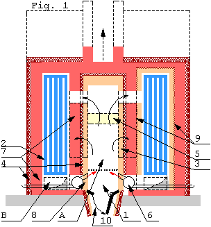
Goal of convective system of the boiler of periodic action Fig.1 to accumulate and transfer heat energy released during combustion of fuel with maximum efficiency. The heat is transferred to walls of the boiler 7, coils of the system of regeneration 6, and to the heat exchanger (water) 2.
Heat energy of the hot gases is distributed between walls of the boiler and the heat exchanger. The bigger is the difference in temperatures between gas flow and an object in the flow the more heat energy will be consumed by the object. Therefore, walls of the boiler should be thick to accumulate heat slowly, and heavily insulated form the outside. The construction can be a single brick wall (left side of Fig.1) or a double wall (with firebrick core) (right side of Fig.1). In the double wall design, an expansion joint 9 is necessary. Such joint is created by laying a thin liner made of ceramic wool blanket or cardboard between the core and the facing.
Goal of the firebox is to release maximum energy from fuel and to transfer it to the convective system with maximum efficiency. It can be done by increasing temperature of combustion at all stages. Increase in temperatures can be achieved by following measures:
1. Design of the firebox that has a zone with naturally increased temperature to achieve a complete burn (like a secondary combustion channel). Our boilers are designed based on "principle of free gas movement" that creates such zone.
2. Placement of the heat exchanger outside of the firebox. This increases temperature of combustion and contributes to a cleaner burn.
3. Optimization of the air supply at all stages.
4. Using of material with high heat conductivity in walls of the firebox 3. This measure allows fast equalization of temperatures of the gas flow and the walls, and more heat transferred into the convective system. For the same purpose, we lay mineral wool 4 in between firebrick walls of the firebox and the brick walls behind.
5. Using of a combustion catalyst 5 made form materials with high heat conductivity. Radiant heat released by the catalyst affects all elements of the firebox and the gas flow.Usually, it is a grate built form thin firebrick.
6. Regenerative technology (pre-heat of the combustion air before entering the firebox). Air is supplied through the regenerator 1 instead of supplying it directly. Gases in the lower part of the bell heat air in the regenerator. Ashes can be removed through an ash-damp into the ash pit 10 or through a hermetic clean-out door. Coil of the regeneration system 6 can supply warmed air naturally (by a natural draft) or by a forced air system (fan). In the last case, there is an opportunity to optimize supply of air at different stages of combustion, and automate the whole combustion process.Walls of the bell 7 are heavily insulated by mineral wool from outside and serve role of a heat accumulator. Such design allows automating the whole heating process by using automatic regulators and circulation pumps.

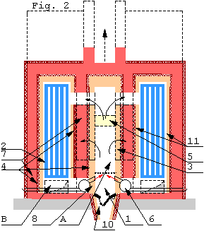
Boilers of a constant action Fig. 2 are designed the same way. Difference is a smaller firebox, and less thermo-mass. Also, there is a need to change the pattern of the heat exchange in the bell. It is necessary for the heat exchanger to absorb more heat and for the walls of the bell to absorb less. This is done by installation of a double wall with mineral insulation 4 between them. Inside wall (core) 11 is built from a material with high heat conductivity (firebrick). It is easier to span core and facing independently. Moreover, firebrick walls in the firebox and in the bell will have different temperature and different expansion. Therefore, it is better to keep them separate. An expansion join filled with mineral wool has to be established between firebrick and regular brick walls. 1" mineral wool blanket will serve the purpose. Such boiler can be heavily insulated from outside if there is no need to heat the room where it is located.
Heat output of the most of the existing traditional boilers working on solid fuel is regulated by control of the air supply, i.e. by changing intensity of combustion. It is well known that highest efficiency of a boiler working on any type of fuel can be achieved only at maximum output. Efficiency of such heating systems heavily depends on percentage of capacity of the system at the current moment. The lower is use of the system, the more fuel is used and the lower is efficiency. This problem is solved in gas and oil boilers by automated control of fuel supply. In solid fuel boilers, this problem can be solved the following way:
Heat energy supplied into the bell is distributed between its walls and the water heat exchanger. Under a prolonged or constant burn, temperature of the walls and the gas flow equalize, and heat exchange happens only in the water heat exchanger. Regulation of the hot water supply into a hydronic heating system can be done be changing:
In the first case, while lowering the heat output we lower efficiency and increase pollution that is not desirable. Here we don't create excess of heat in the boiler. The process of regulation by changing the speed of water circulation looks differently. While decreasing the speed of circulation, we lower heat output into the heating system. At this time, there is no drop in efficiency, but excess of heat is created and it has to be used somehow.
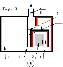
Heat excess can be accumulated by the scheme shown in Fig. 3. Boiler of the constant action C is shown to the left of the axis E. System "single- or double-bell" D, which accumulates the excess heat is shown to the right of the axis. Legend: 1 – exhaust; 2 –object receiving excess heat; 3 – by-pass channel; 4 - by-pass damper; 5 – thermometer, 6 – exhaust gases analyzer.

The scheme works the following way: Depending on combination of exhaust gases, analyzer 6 (Fig.3), operates the system of regeneration 6 (Fig.1), and optimizes combustion air supply. T depending on temperature of the exhaust gases thermometer 5 operates damper 4 opening or closing it. If there is no heat excess, hot gases from the boiler flow through exit 1, channel and open damper 4 into the chimney. If there is heat excess, damper 4 is closed, and hot gases go into heat accumulator D.
Usage of the accumulated heat is not described in this article. I just have to notice that goal of the convective system D is analogical to scheme shown in Fig. 1 and Fig. 2. By such scheme, we can use excess heat from various technological processes in industry.
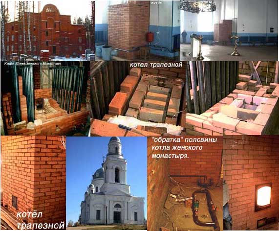
Our boilers built by the scheme shown in Fig. 2 show impressive results even without the system of regeneration. In December 2003 we have finished a boiler for a 3-story brick building in a monastery where two lower stories are designed to have residential units for monks, and the upper story will serve as a large temple. The boiler was designed to heat lower two stories. Although the building was under construction and the temple at the third floor didn’t have a roof yet, wall units were installed on the first and the second story and the system was already working. Some windows were already installed; others were just covered with plastic film. Slab between the second and the third floor is made from separate cored concrete units and was not insulated yet. The third floor didn’t have a roof. Even with all this conditions and outside temperature of minus 16 degrees Celsius, temperature inside was +12 at the first story and +15 at the second story! Walls and ceiling slabs had +10 degrees! Temperature of the uninsulated facing of the boiler reached up to 130 degrees Celsius. People serving this boiler were amazed by its characteristics. They burned freshly cut pine because they didn’t have dry firewood around, and nevertheless, they got only one bucket of soot left after 15 days of constant burn! They experimented by throwing a piece of rubber into the firebox, but they didn’t get any dark smoke. All they got were white vapors! When during maintenance boiler wasn’t fired for 12 hours, temperature of the water dropped only 20 degrees Celsius. It has to be noted that boiler wasn’t insulated, and the building wasn’t finished yet.
At the current time, Russian government building authority recommends several designs of wood-burning boilers for heating and domestic hot water production in which heat exchanger is located inside the firebox. Most of the boilers at large central municipal heating stations have the same location of the heat exchanger. Such boilers have several drawbacks that are hard to fix due to imperfection of their convective system. Such system consists of parallel or consecutive channels. It creates great resistance to the gas flow, has limits for the shape and volume, has uneven and inefficient heat distribution. It is impossible to insert heat exchanger (water coil) into the channels, as it would create even greater resistance. The only place for the coil is in the firebox. But as has been said above such location dramatically lowers efficiency and increases pollution.
Our system of design offers unbelievable flexibility and allows to design and
build multifunctional boilers and stoves of any size and shape; stoves with
unique features and functions. Electric heating elements, hot water coil, a
cooktop, a bakeoven, steam generator, heat exchanger, etc. can be easily installed
in our stoves. Steam generating boiler can be designed by our system as well.
Our theory can be applied to systems working on all types of fuel. Our system
gives an opportunity to use high technology in masonry heaters/stoves. It is
possible to automate fuel loading, combustion and heat output control. I consider
this direction in development of system of heat energy source perspective. It
corresponds to energy savings and use of  renewable
energy sources requirements.
Our work allows using of locally available fuel from renewable sources, and results in real energy savings. Converting to our system doesn’t require great spending because it can be done by "self-built" principle.
For further development of our system, it is necessary to continue work on automation of fuel loading and optimization of combustion process. Testing has to be done to define temperature of gas flow and details of boilers at different stages of combustion. This data is necessary for the calculation of the projected heat output for the future boilers and stoves. The testing will help to achieve maximum efficiency of the boilers by defining the best combination of materials to be used and the best constructive solutions. This work has to be described in understandable graphs and formulas, which would serve as the base for design of new boilers and stoves. I have prepared a proposal for research that is available here:
http://www.stove.ru/index.php?lng=0&rs=104 .
I would be very thankful to anyone who would become my proponent for the ideas described in the article. I would also appreciate help with getting the article evaluated by an interested organization in the energy savings field, or published by a magazine interested in such topic.
I.Kuznetsov
620042 Ekaterinburg, Russia
Pobedy str., 51-87
voice: (3432) 32-94-90, 37-24-96
e-mail: igor@stove.ru
http://stove.ru
Translated, Alex Chernov, Canada, chernovalex@yahoo.ca, voice 8.10.1. 416 708 8139