Les Vosges Project notes
These notes detail the installation of a thermal break between the core and footing. The thermal brake is optional and reduces transfer from the base of the heater to the footing, and on into the ground. Many heaters are built upon grade with no thermal break at all and no noticeable detrimental effect. Obviously though cutting transfer into the ground results in net gain.
Materials:
Refractory Brick
Bonny B40SR 220 x110 x 60mm
Refractory Mortar
Refracol 8a
Castable Refractory Concrete:
Refracol Cast 550-10
Ceramic Wool:
Superwool 607 HT
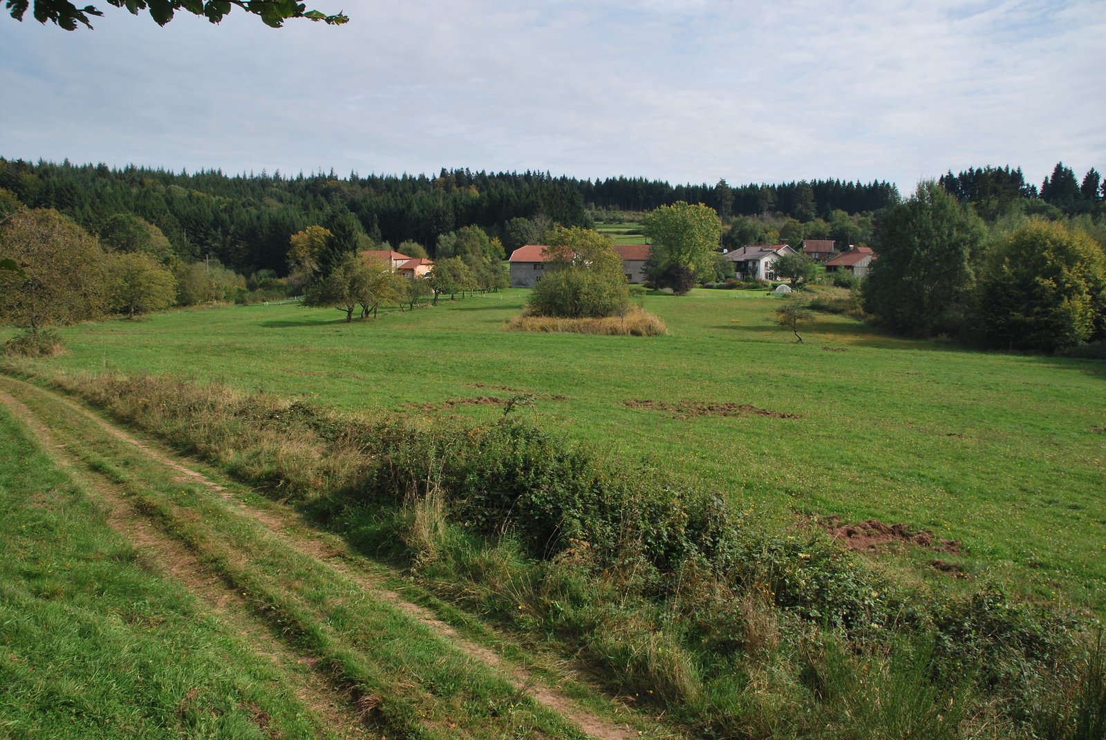
The lay of the land.
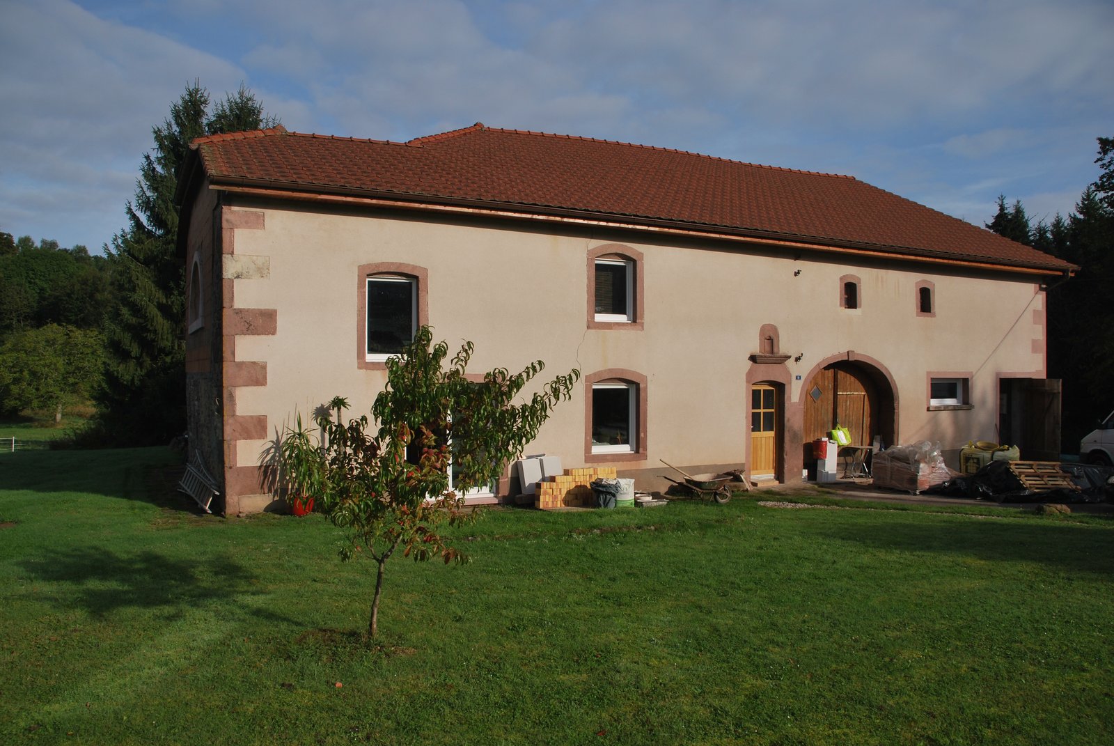
The site. Typical of the farm houses built in the region during the 19th century. The pink stone trim and tone of the rendering are from a detrital rock, known locally as Le Gres des Vosges.
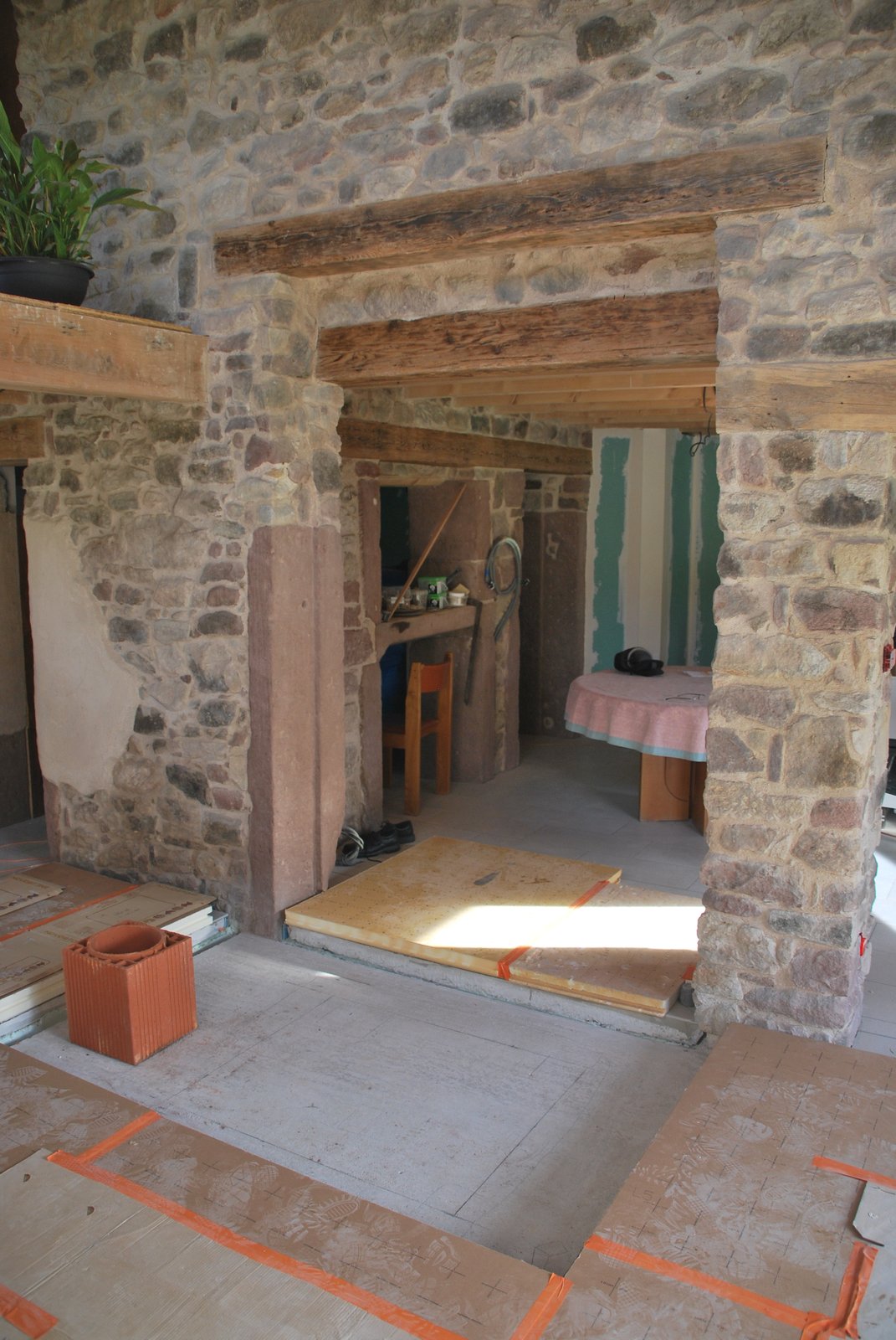
Located between the kitchen and main living area, the heater will be free standing just in front of the opening in the wall: i.e. the wall will not be closed around the heater. The fire box loading opening will face the living area and the oven loading opening the kitchen.
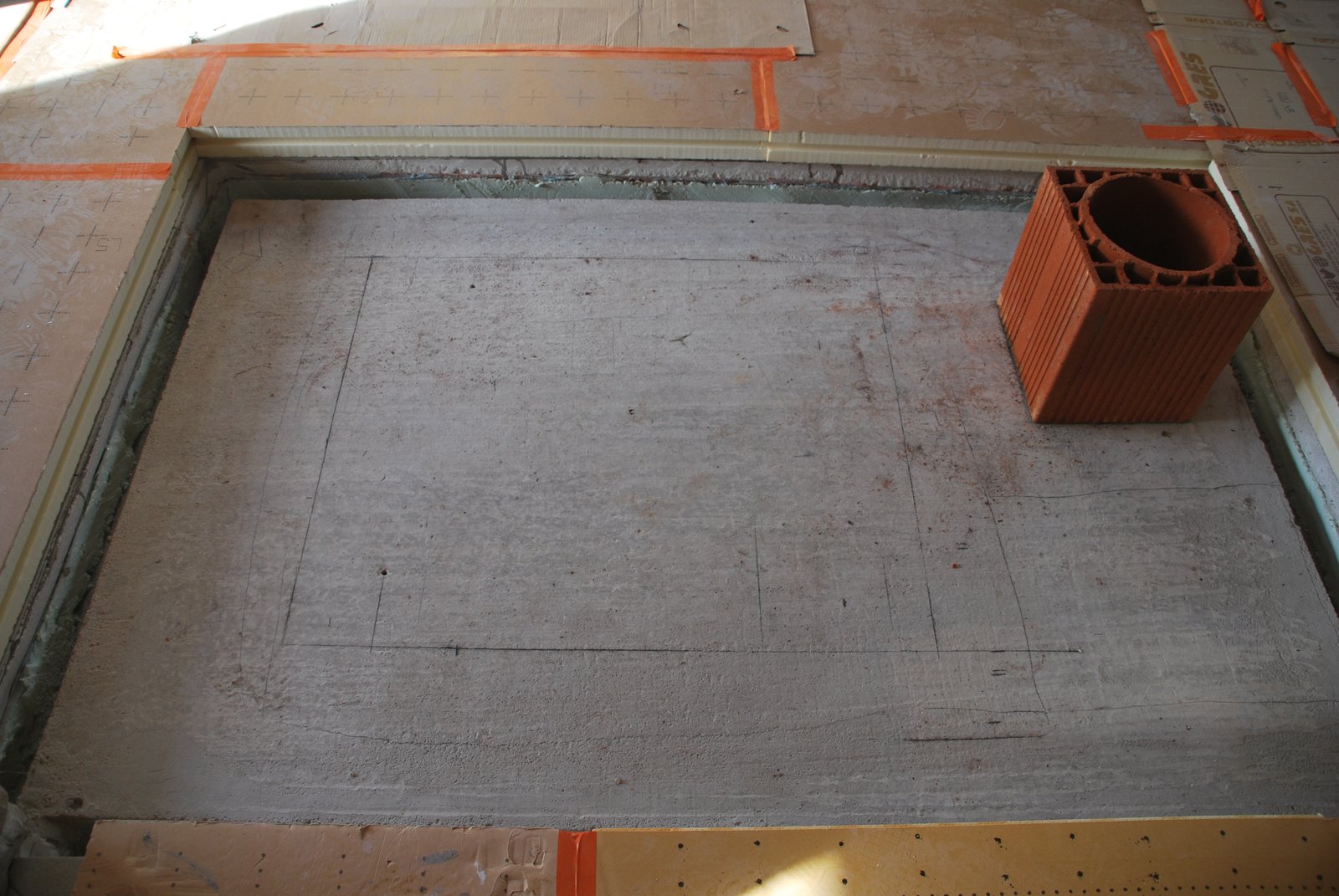
The flue tile is positioned in relation to the necessary clearances from the wooden superstructure of the roof. The footprint of the core is marked out in relation to the flue tile.
The flue tile is positioned in relation to the necessary clearances from the wooden superstructure of the roof. The footprint of the core is marked out in relation to the flue tile.
The 30cm thick reinforced concrete footing. The footing is completely independent of the slab forming the rooms floor. Sufficient clearance is left from the footing to the (blue) expanded polystyrene used to insulate the floor.
In this case the floor of the room has already been finished in ceramic tiles. Visible elements of the floor are: from top to bottom, Sheets of expanded polystyrene (beige) layed to protect the finished ceramic floor during the project, ceramic tiles, a layer of cellular concrete, and beneath that a layer of expanded polystyrene (blue) insulation.
The footing is poured approximately 7cm below the finished floor to accommodate the thickness of the thermal break. If the footing is not recessed, the thickness of an added thermal break between core and footing will make the whole core approximately one course of brick higher. This would be a problem only if there were an overall hight limitation due to an abnormally low ceiling.
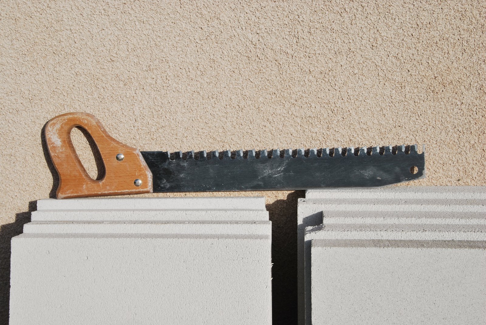
Sheets of 5cm thick cellular concrete, and the carbide toothed saw used to cut them.
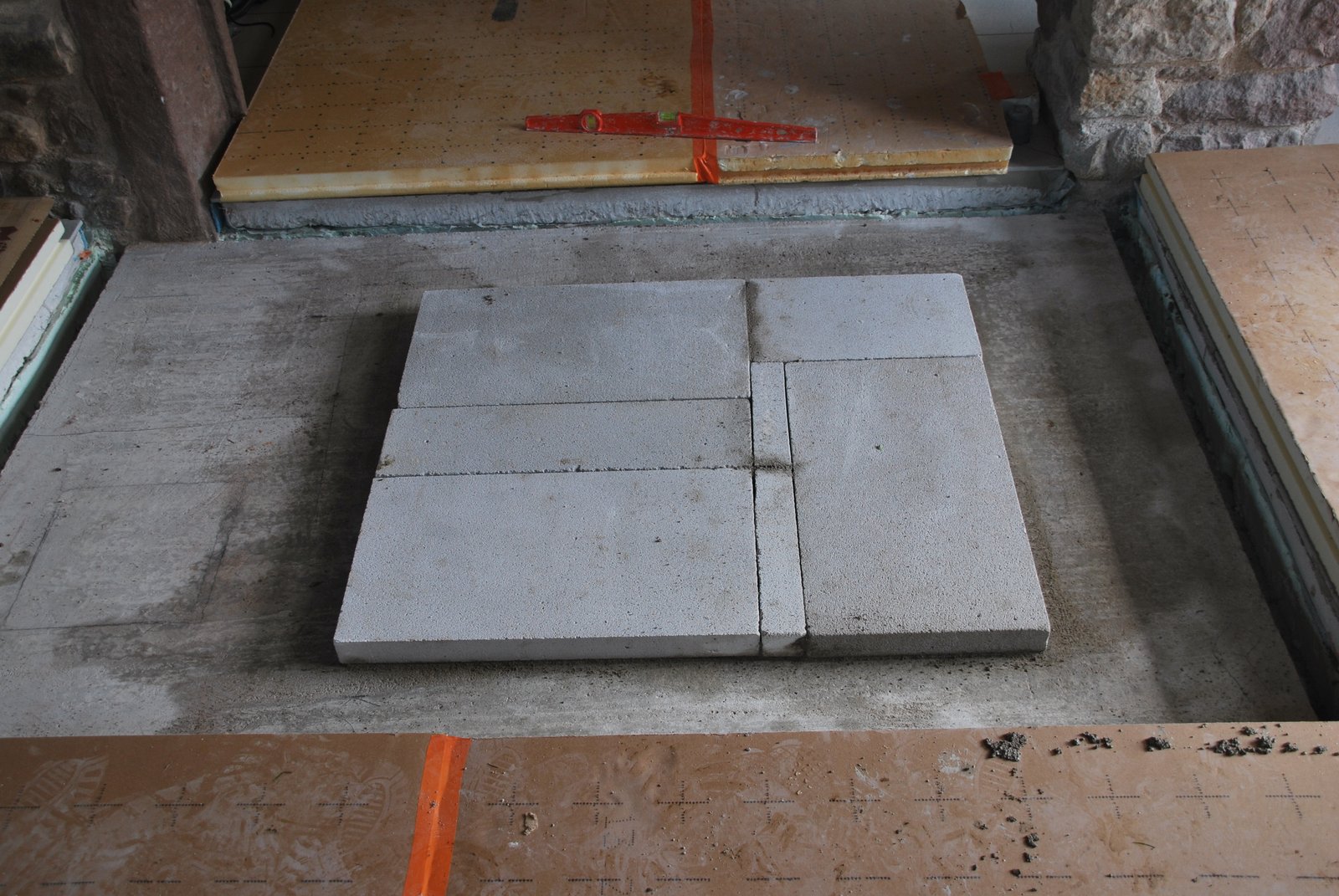
The thermal break of cellular concrete layed in Type N mortar. With dry head joints.
Note that the thermal break has been layed only below the footprint of the core. The facing will also be layed upon cellular concrete, though this will be layed separately just before starting the facing. If layed at this stage, due to its fragility, any cellular concrete not directly beneath the core, would be destroyed by foot passage around the core during its construction.
This particular cellular concrete panel has a minimum compressive resistance of 3.2 Mpa Its dry thermal conductivity is 1.3
Note that the thermal break does not extend beneath the chimney. There is little heat loss from the base of the chimney, but there is relatively high compressive force concentrated on the footprint of the first row of brick of the chimney. This will depend upon the hight of the chimney, though as heat loss would be minimal, it is preferable to start the chimney directly upon the footing. The stove having a large footprint can be built upon a thermal break of cellular concrete panels, without compressive resistance being an issue.
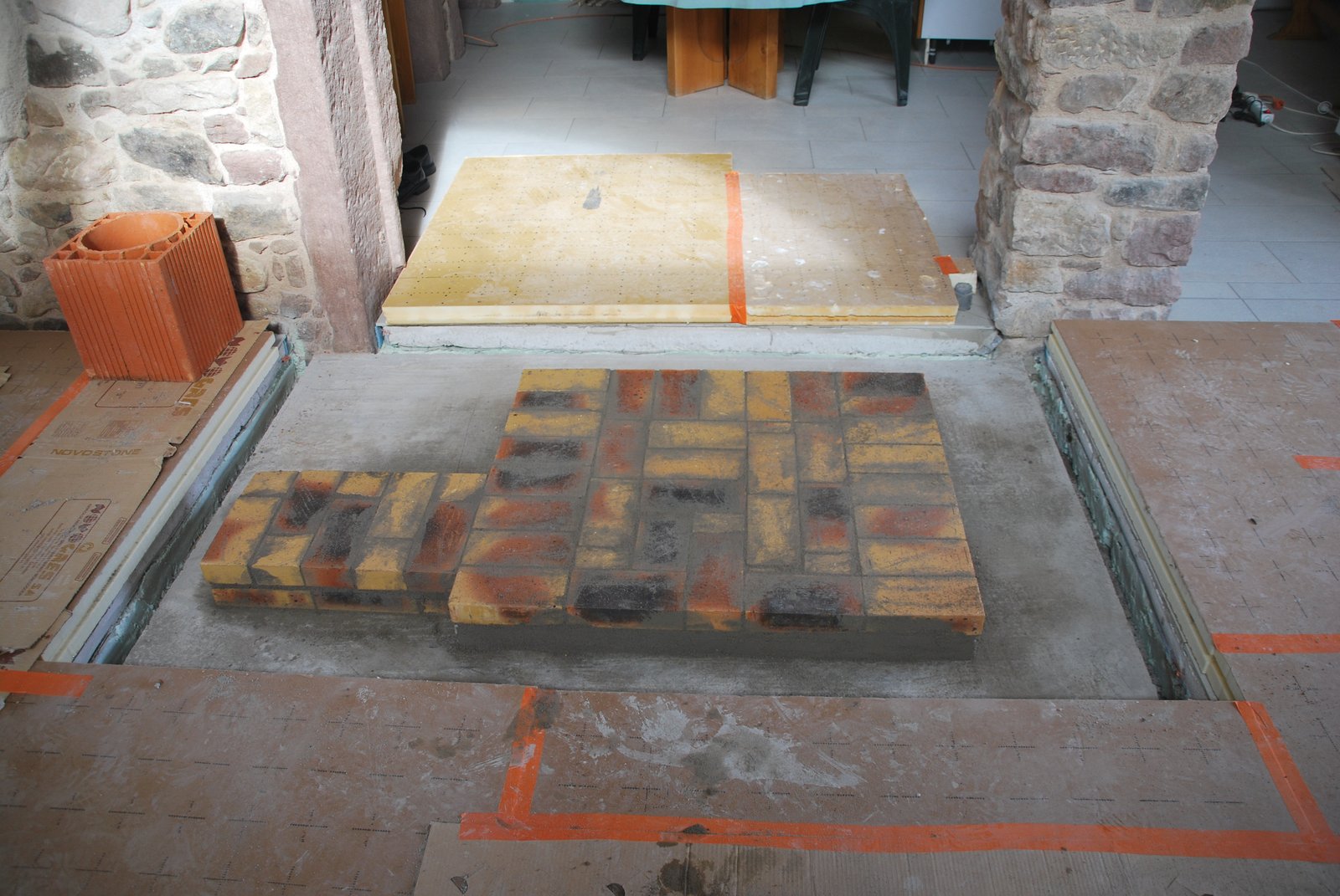
A course of common brick (Leopard) is layed in Type N mortar upon the thermal break. The exposed edges of the cellular concrete are parged with mortar to protect them during the cores construction.
Two courses of common brick are layed directly beneath the footprint of the chimneys flue tile.
This course of common brick provides a clay base to the smoke path in the manifolds and base of the chimney. It also lifts the core up, and away from, the expanded Styrofoam insulation in the surrounding floor.
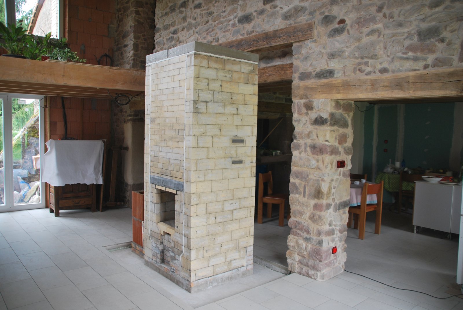
The finished core.
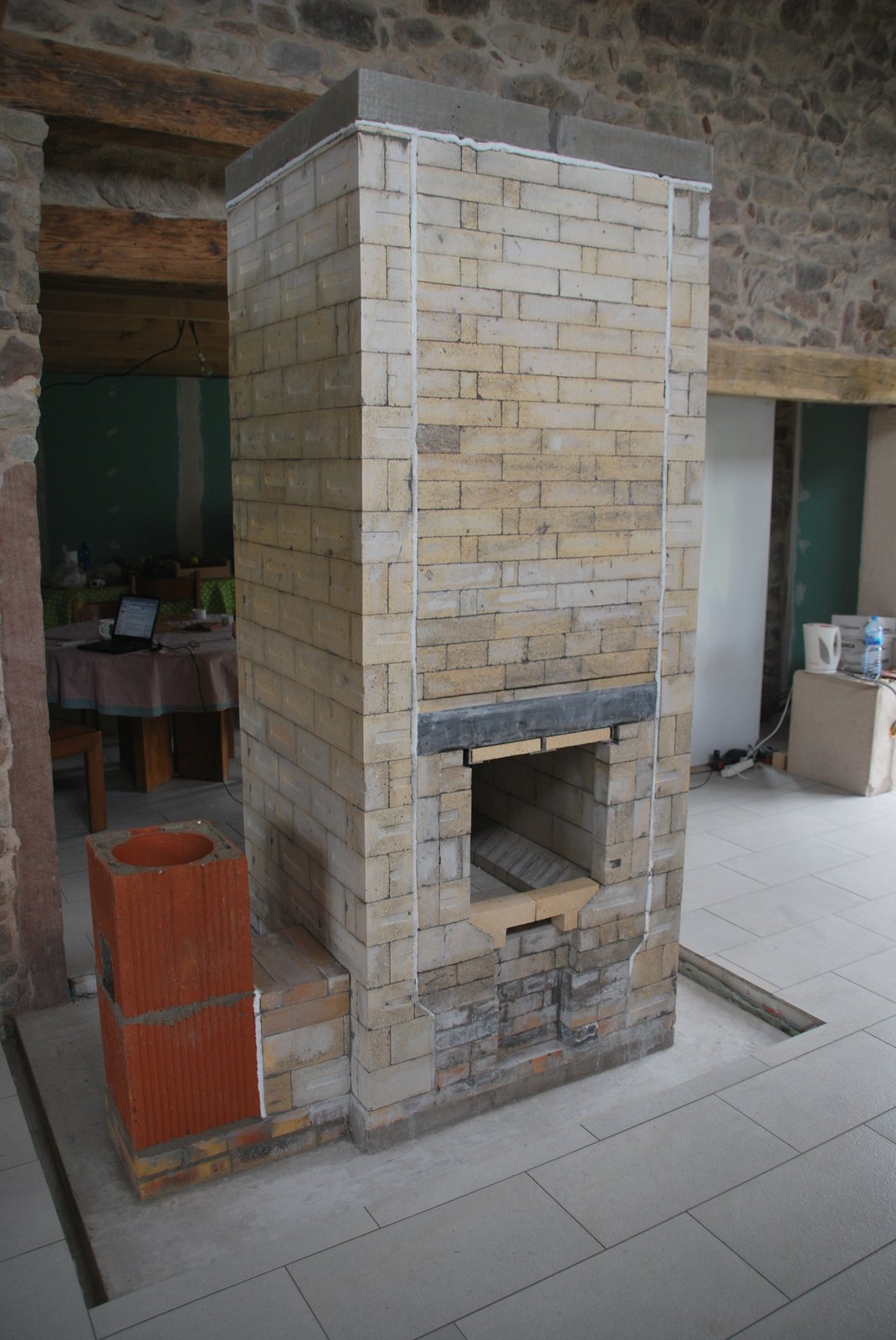
The core showing the chimney connection and first two flue tiles.
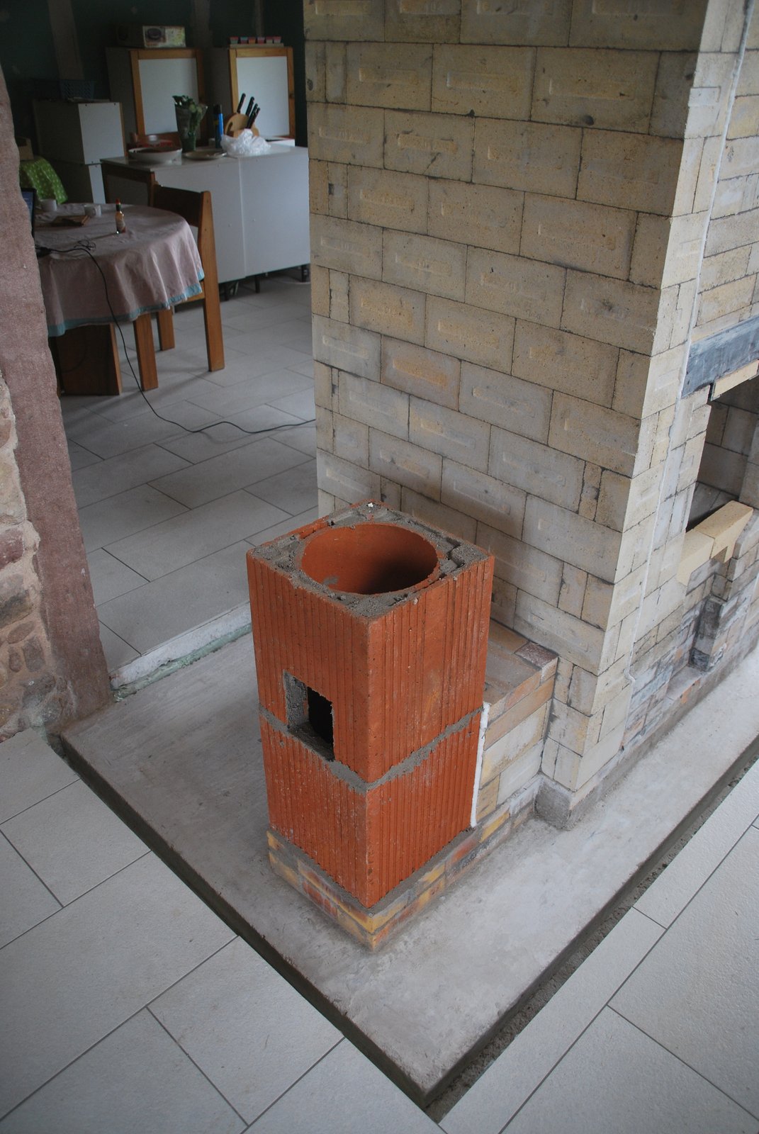
Detail of the chimney connection. The access hole is cut into the second tile to avoid having two openings cut in the first tile.
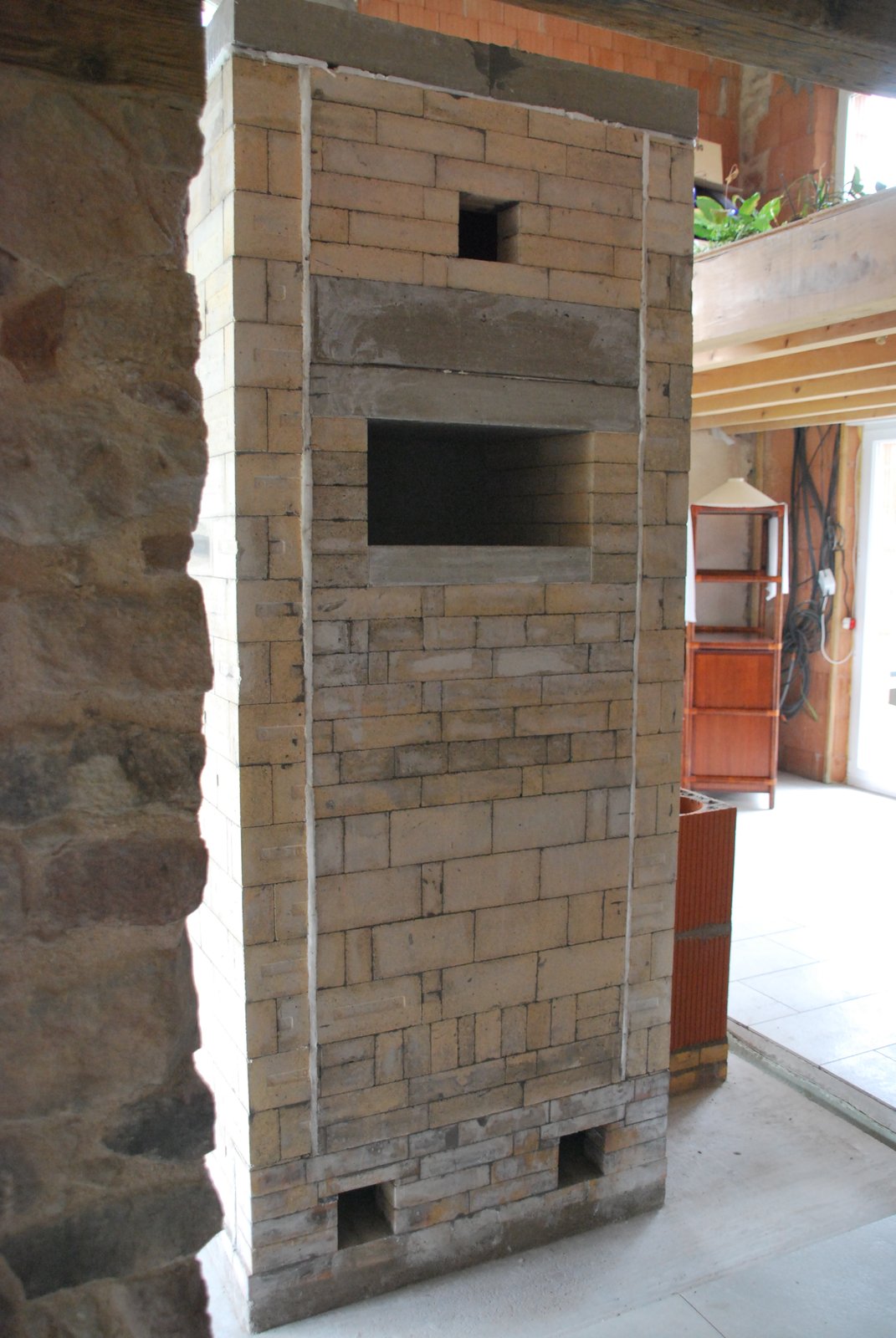
The core seen from behind. The access opening above the oven is to allow cleaning of the side channels should they become blocked with fly ash. This is never the case when a stove is only fired with hard wood, but can occur if soft wood is burnt, particularly pine.
Small particles of ash are carried through the smoke path with the draw and cling to the surfaces. These particles can, when coming from pine, gradually accumulate, causing the draw through the stove to become gradually weaker.
The channels can be accessed through the traditional access openings in the manifolds, and the oven top via the fire tube. The additional opening above the oven only makes cleaning easier should it become necessary. If not necessary it should be avoided as it has, unlike the openings at the base of the stove, a tendency to spill. The cast iron door of the access opening will need to be well gasketed.
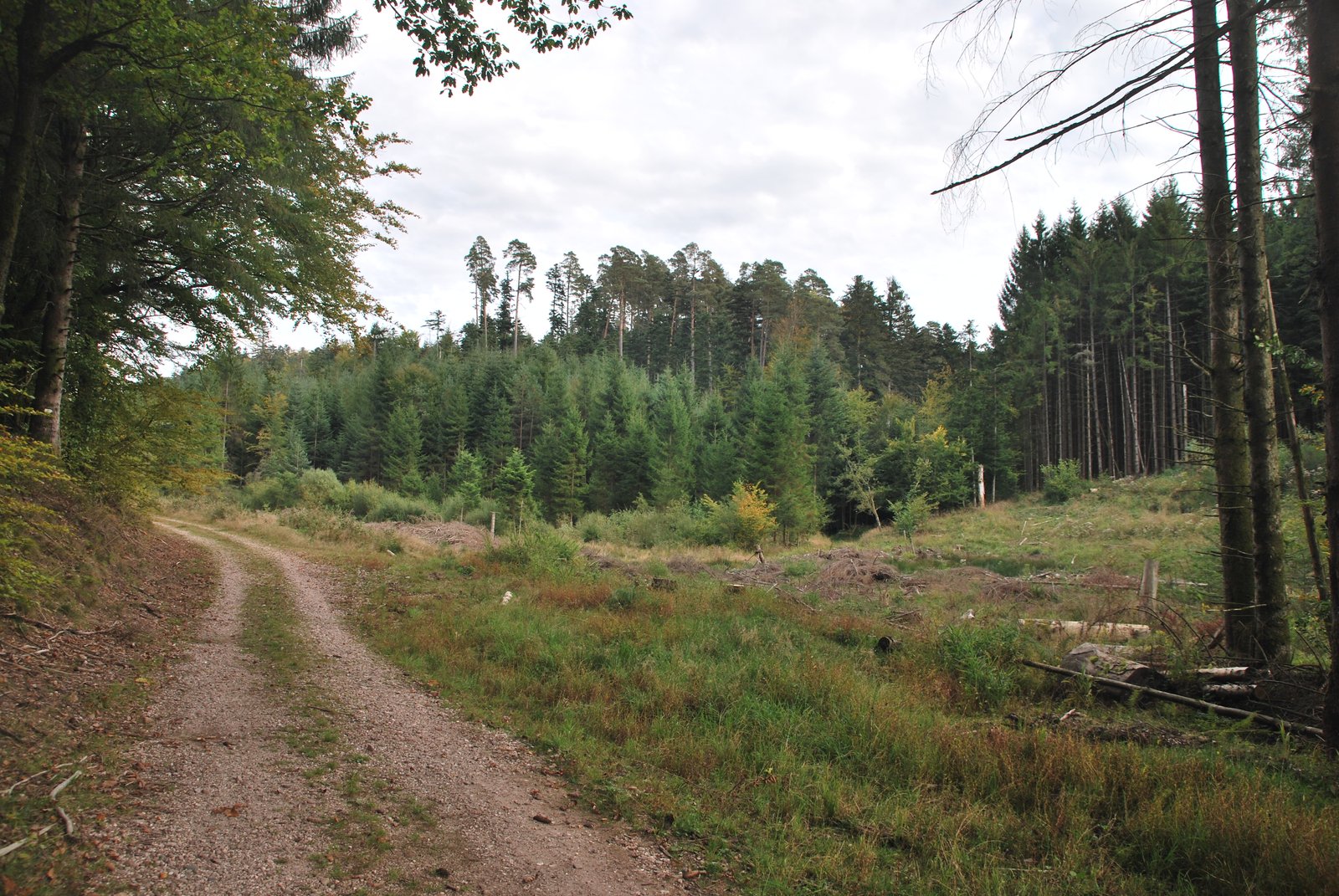
A stand of Pinus Sylvestris (centre). A species that is extremely common in this region and produces large amounts of fly ash.
Marcus Flynn
2014
