Grind Slowly Moudre Fin in Stanbridge East
Detailed below is the combination of a contraflow takka with bell captivation chamber in the Empire Loyalist settlement of Stanbridge East

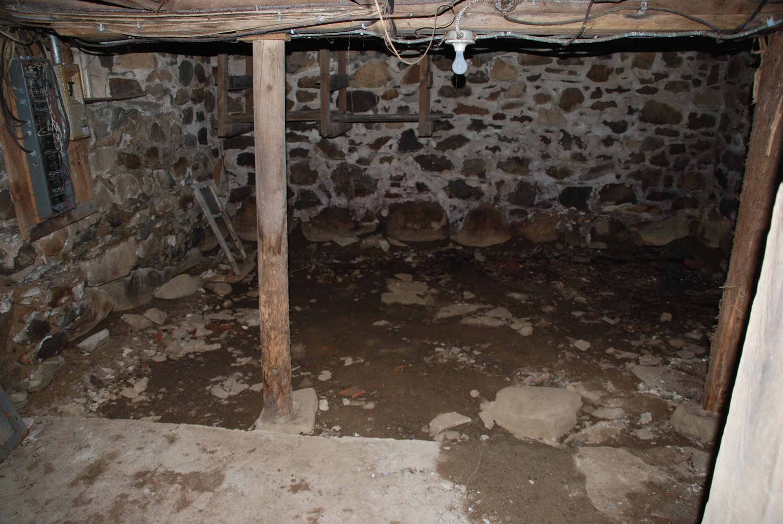
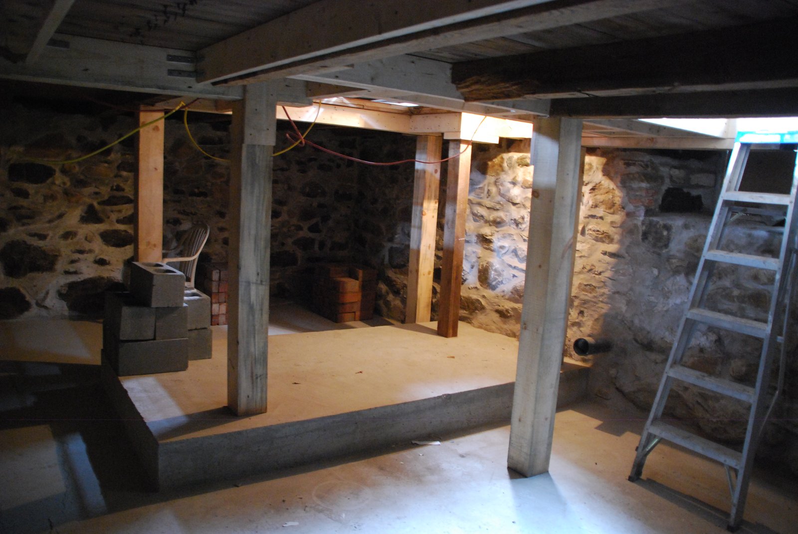
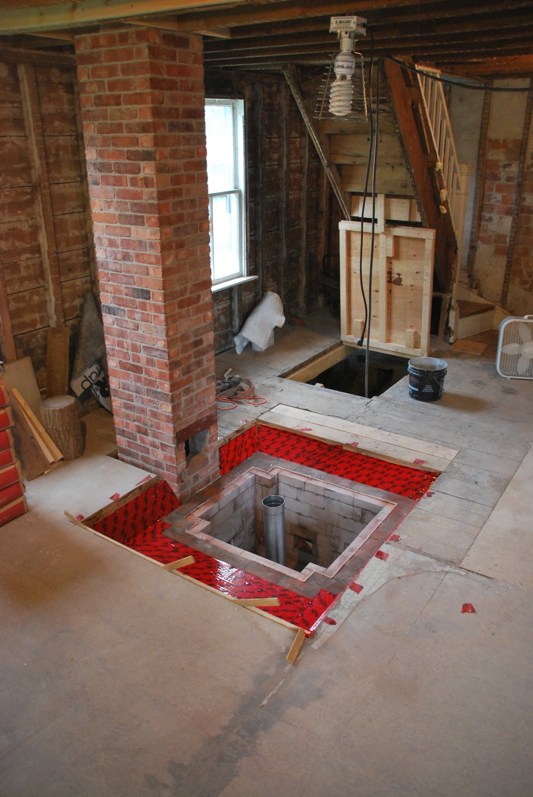
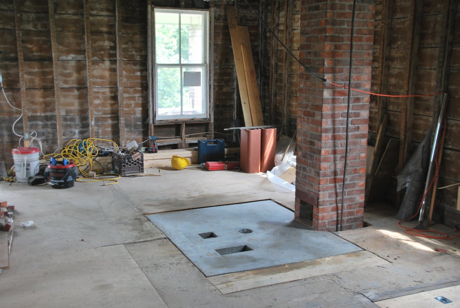
The one and a half story house which was built in 1897 from brick made in the village, rests upon a 6 foot deep basement formed by 2 foot thick stone walls. It has been known, until now, as notoriously cold.
It should be noted that the builder of the house was of Huguenot decent, his ancestors leaving France for America during the Wars of Religion, and then fleeing the newly formed United States for Quebec after the American Revolution.
His name was Charles Manly Blinn. His great grandson and local legend, Pumpkin Blinn, still lives across the road.
The objective would be to build a stove on the first floor that would also keep the basement above freezing point without using electricity, or an auxiliary RWA.
Building a contraflow with side channels that extended into the basement was an option, but this would have necessitated two sets of manifolds, one in the basement and a second in the usual position at the bottom of the stove in order to allow the employment of a bypass directly into the chimney. Also there would be a lot of mass, in an area where it was of little benefit, considerable friction from the channel walls, and way less available surface.
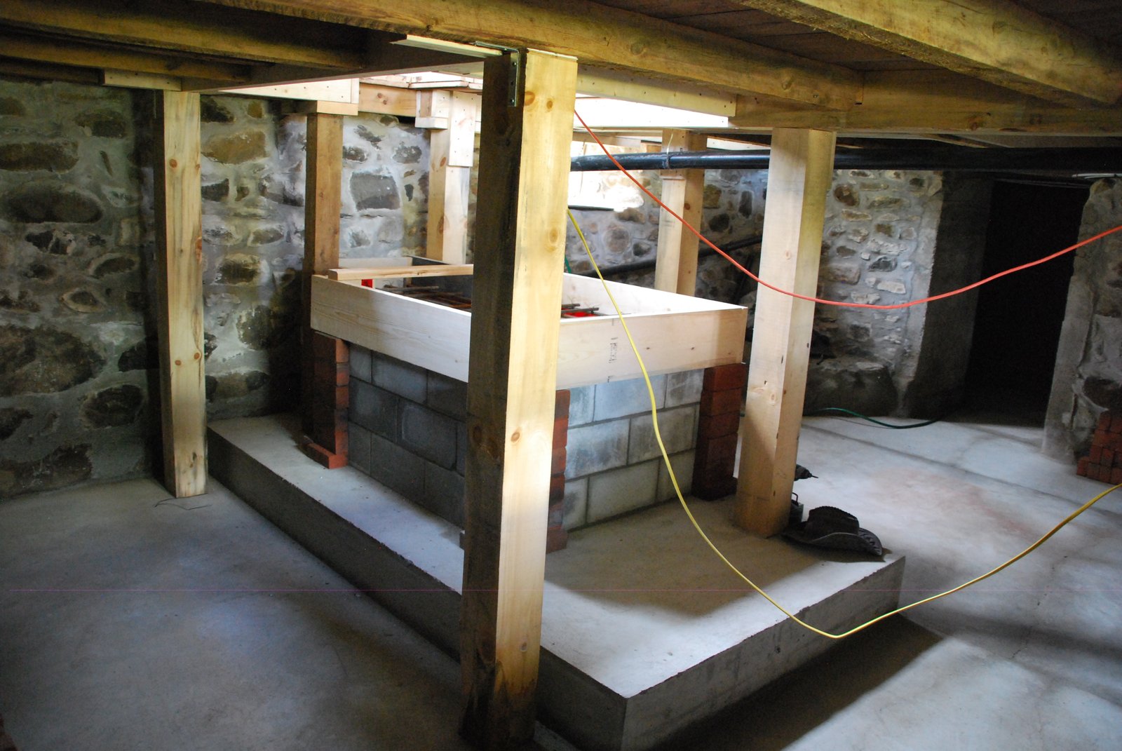
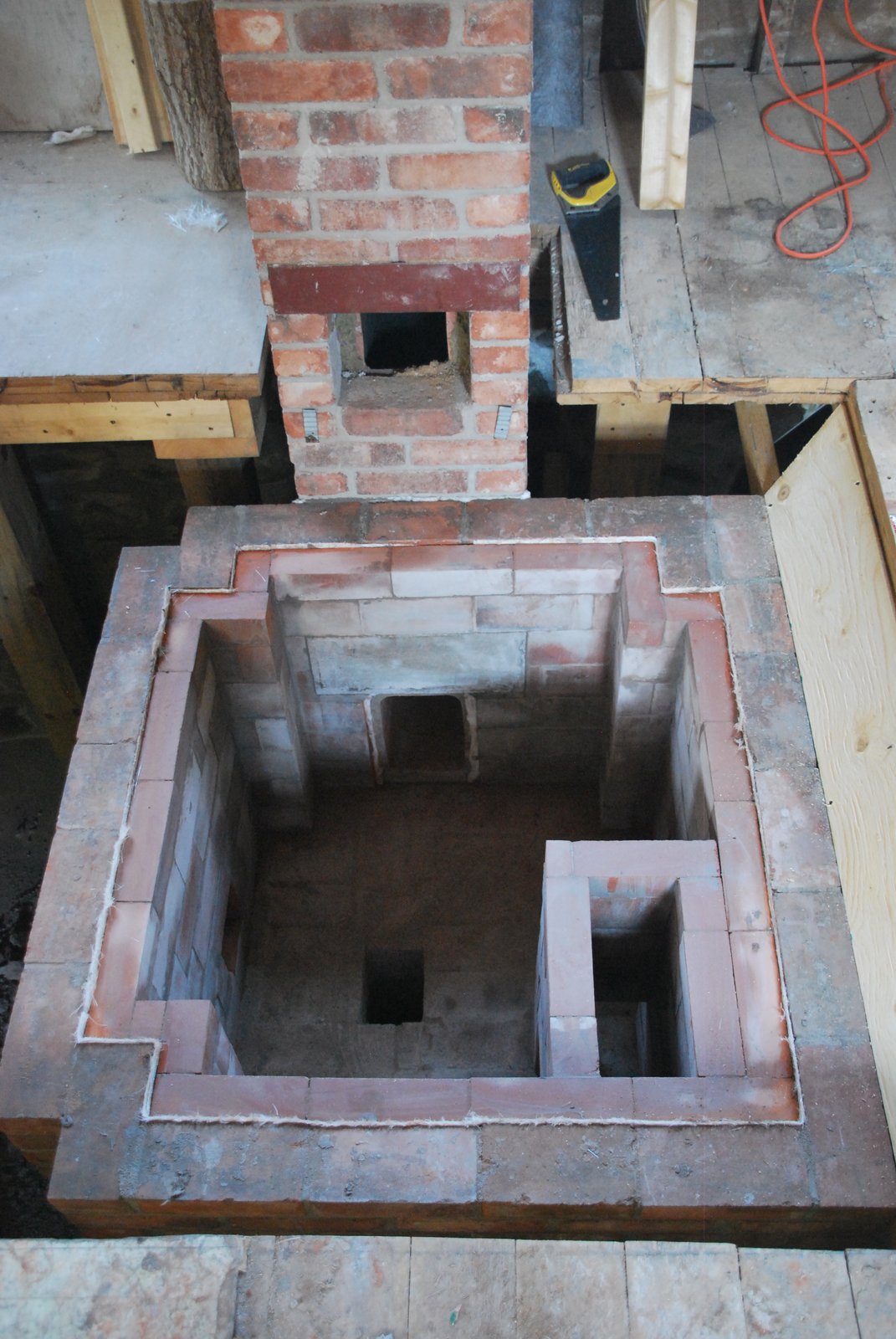
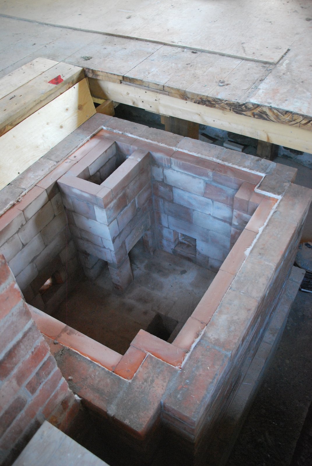
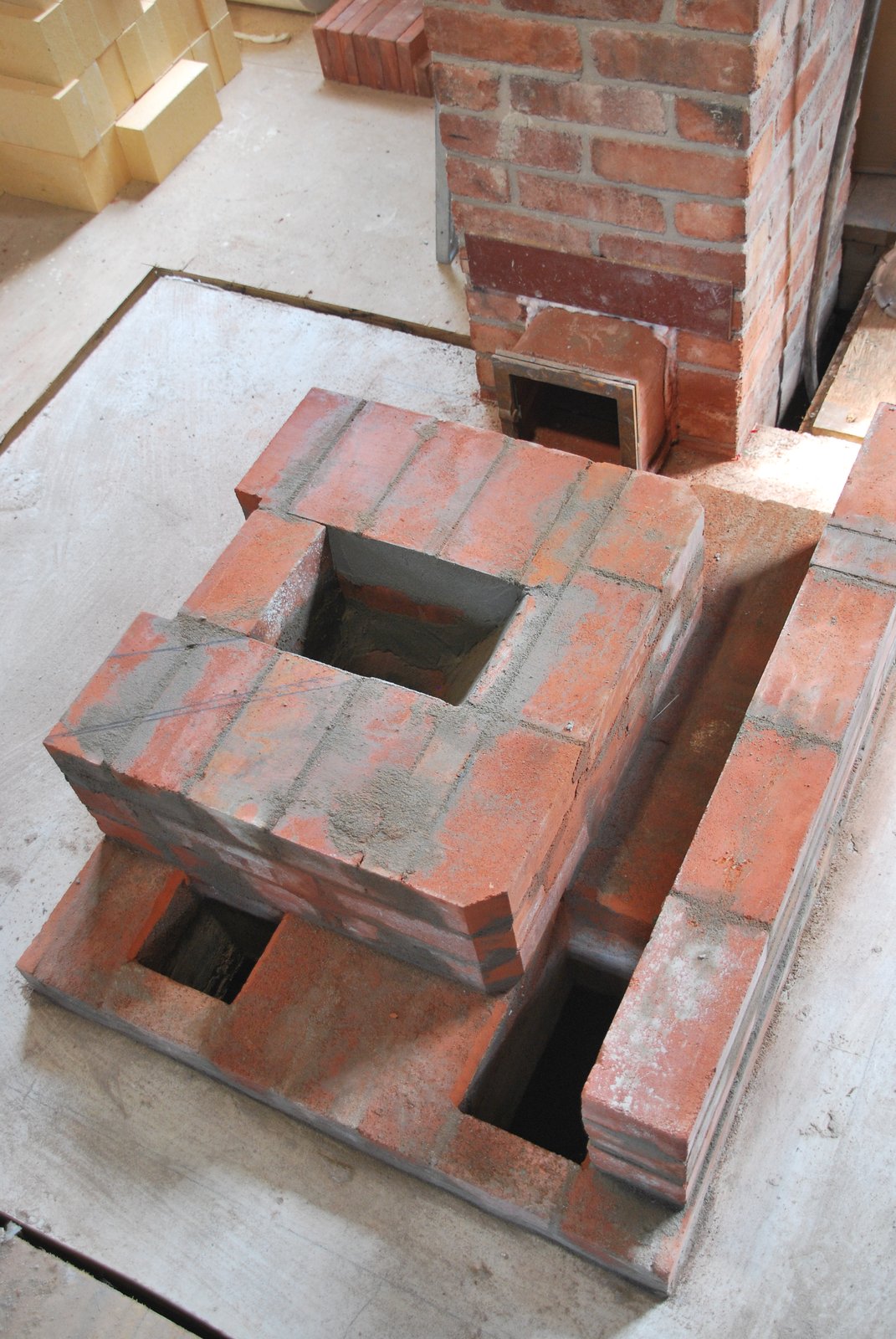
The final plan was to build a standard contraflow stove that would, as an alternative to flowing directly into the chimney, be drawn into a captivation chamber below the stove, in the basement, and then into the chimney. The captivation chamber would have the same footprint as the stove and its foundation, and occupy the top 3 feet of the 6 foot high foundation. The bottom three feet of the foundation would be an ash dump.
Throughout the text the captivation chamber will be referred to as bell.
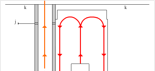
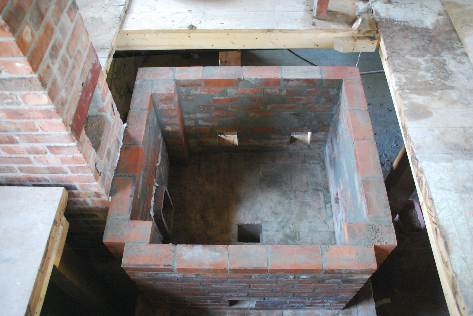
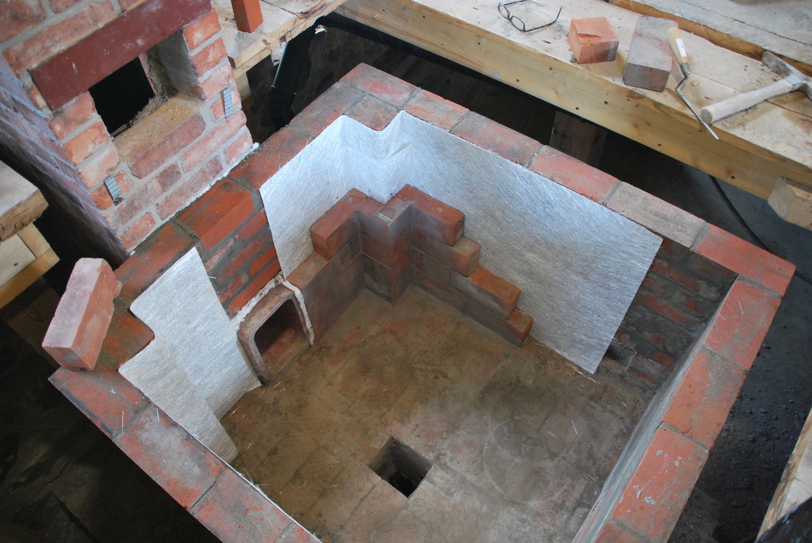
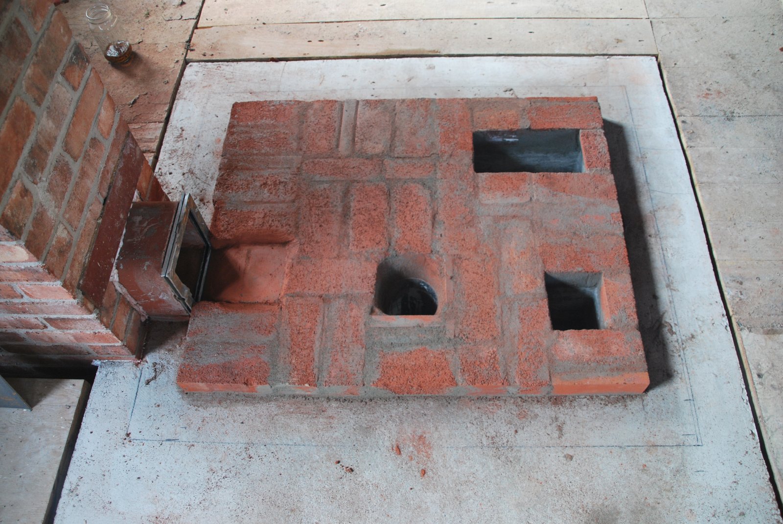
It was decided to abandon this down-channel in favour of two openings at the top of the bell. The channel would have conveyed the gasses to the bottom of the bell, but its walls and added corner may have slowed down the stream to the point where combustion efficiency would begin to drop.
By removing the down-channel the risk of drag from it would also be removed. With out-channel hot gasses would be drawn in to the upper portion of the bell and cooler gasses drawn out from the bottom. Concerns were that the inflow may disrupt the free gas movement within the bell, and that the bottom of the bell would be abnormally cold.
N. Senf and A. Chernov were consulted upon this.
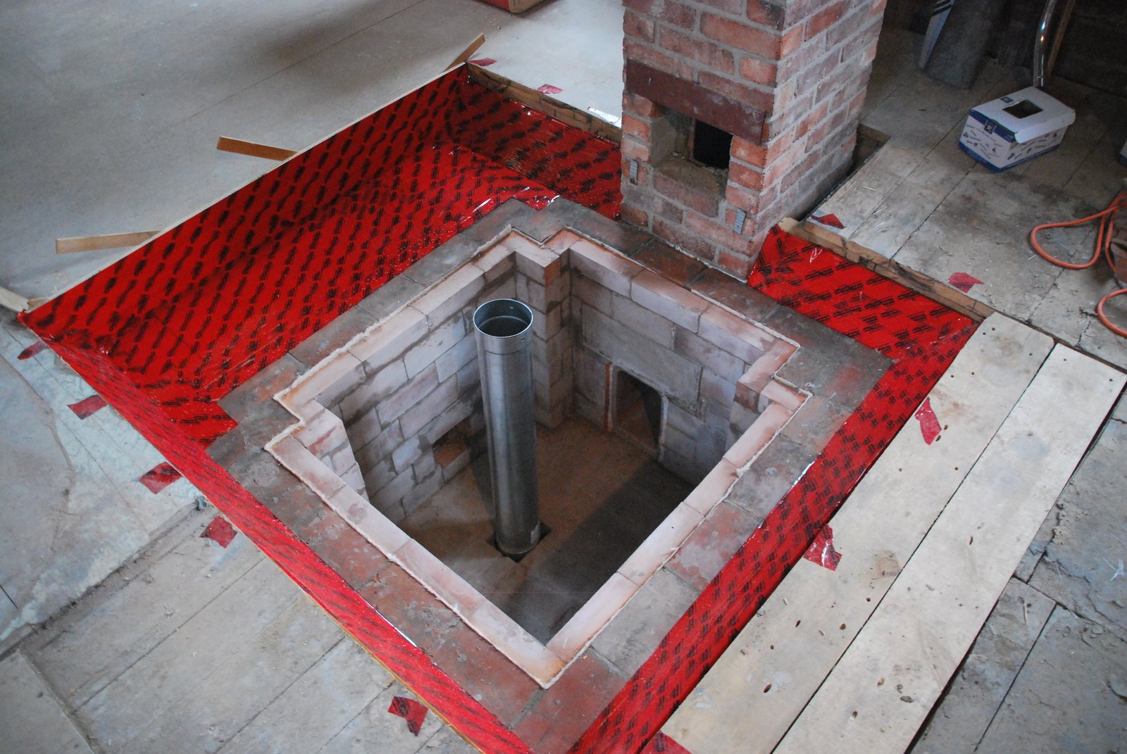
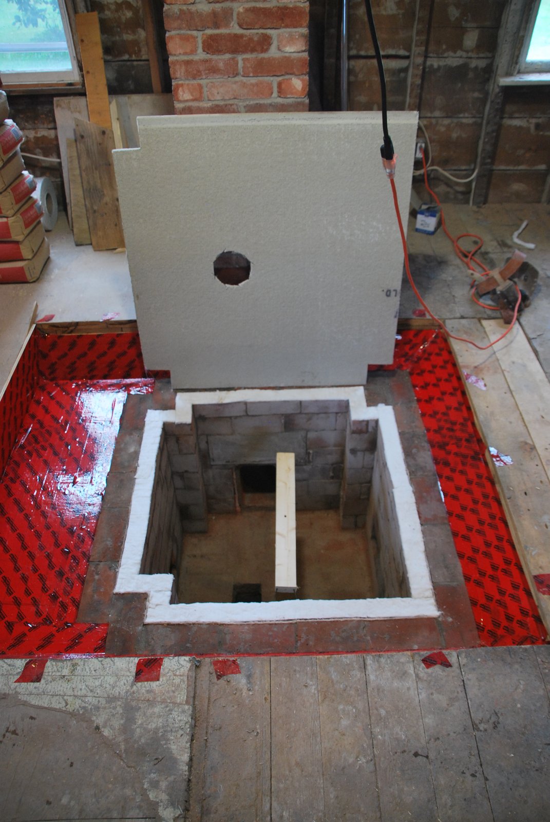
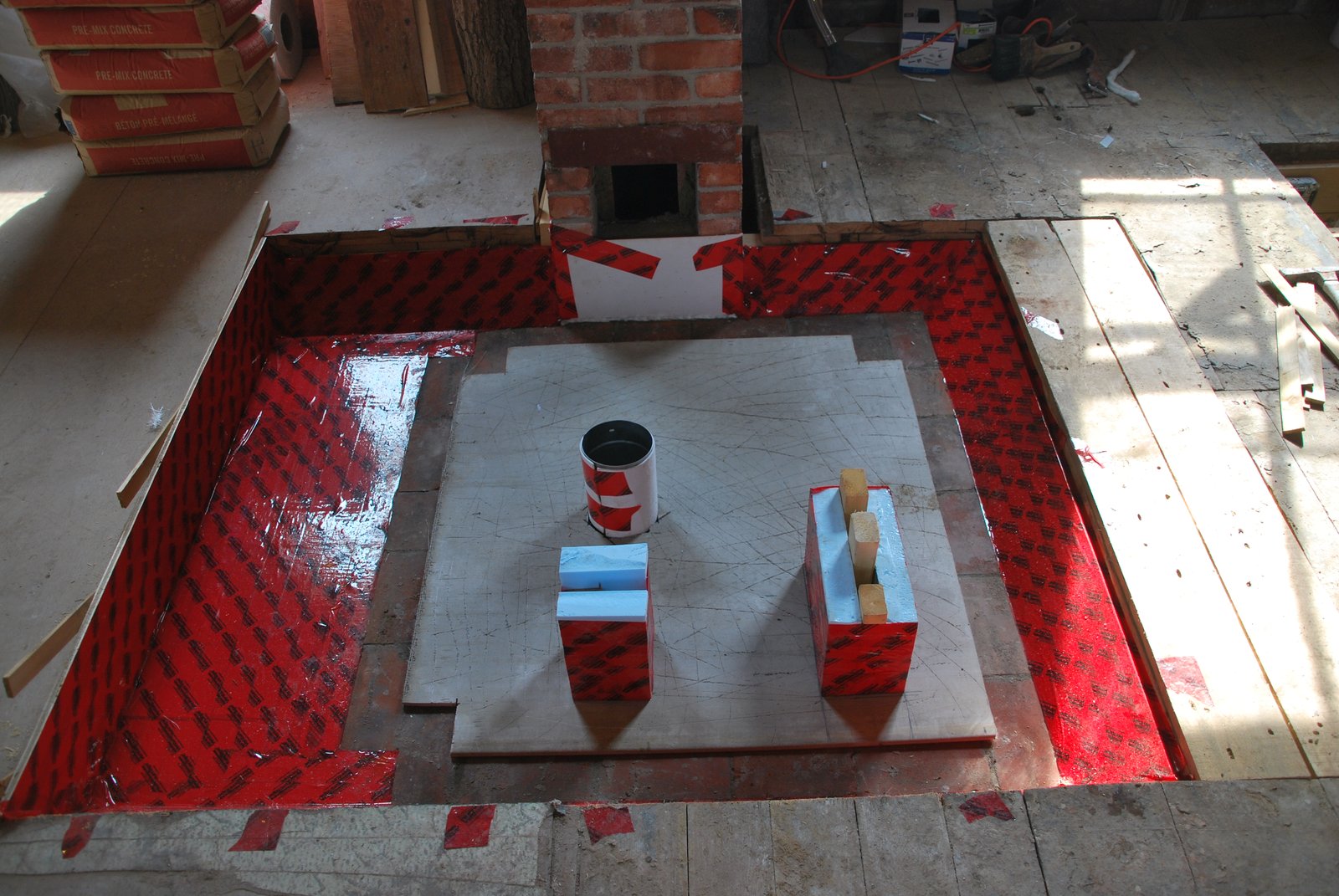
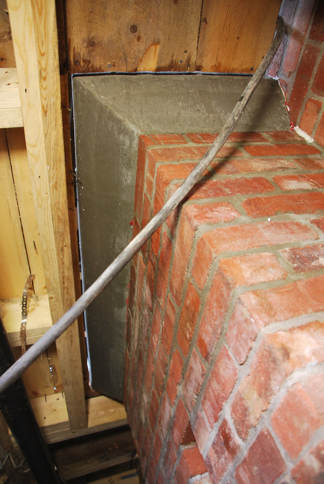
Note: The slab was armed with 5/8 ths re-bar before pouring.
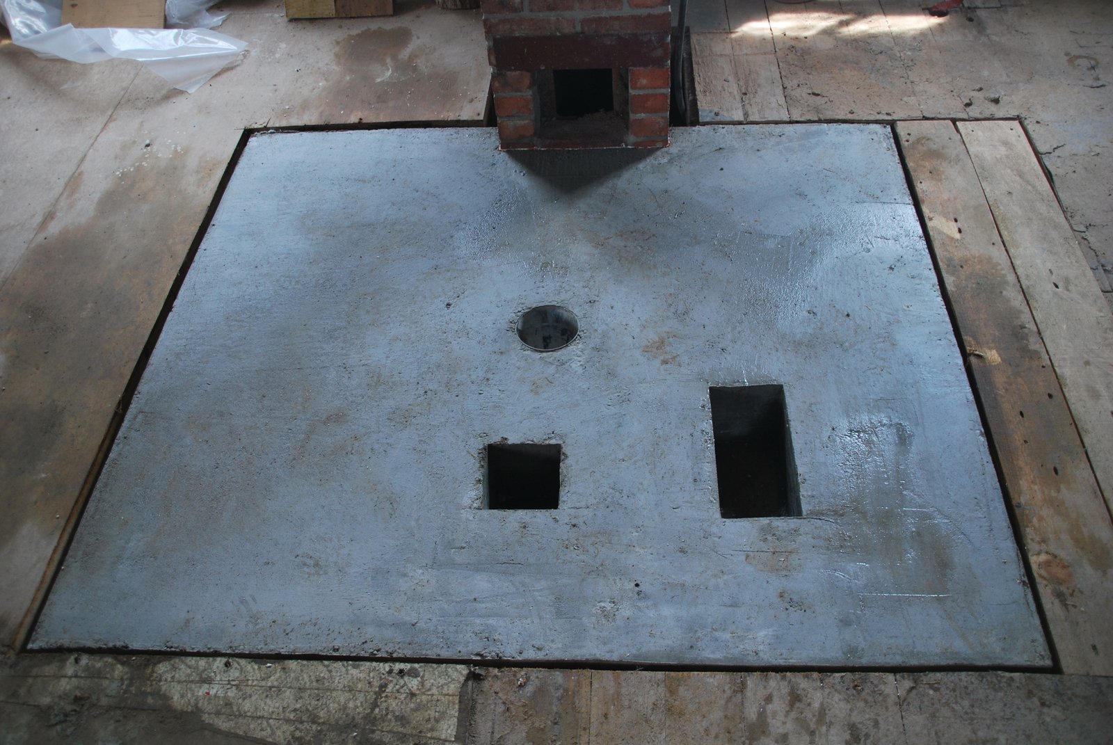
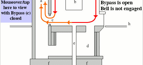
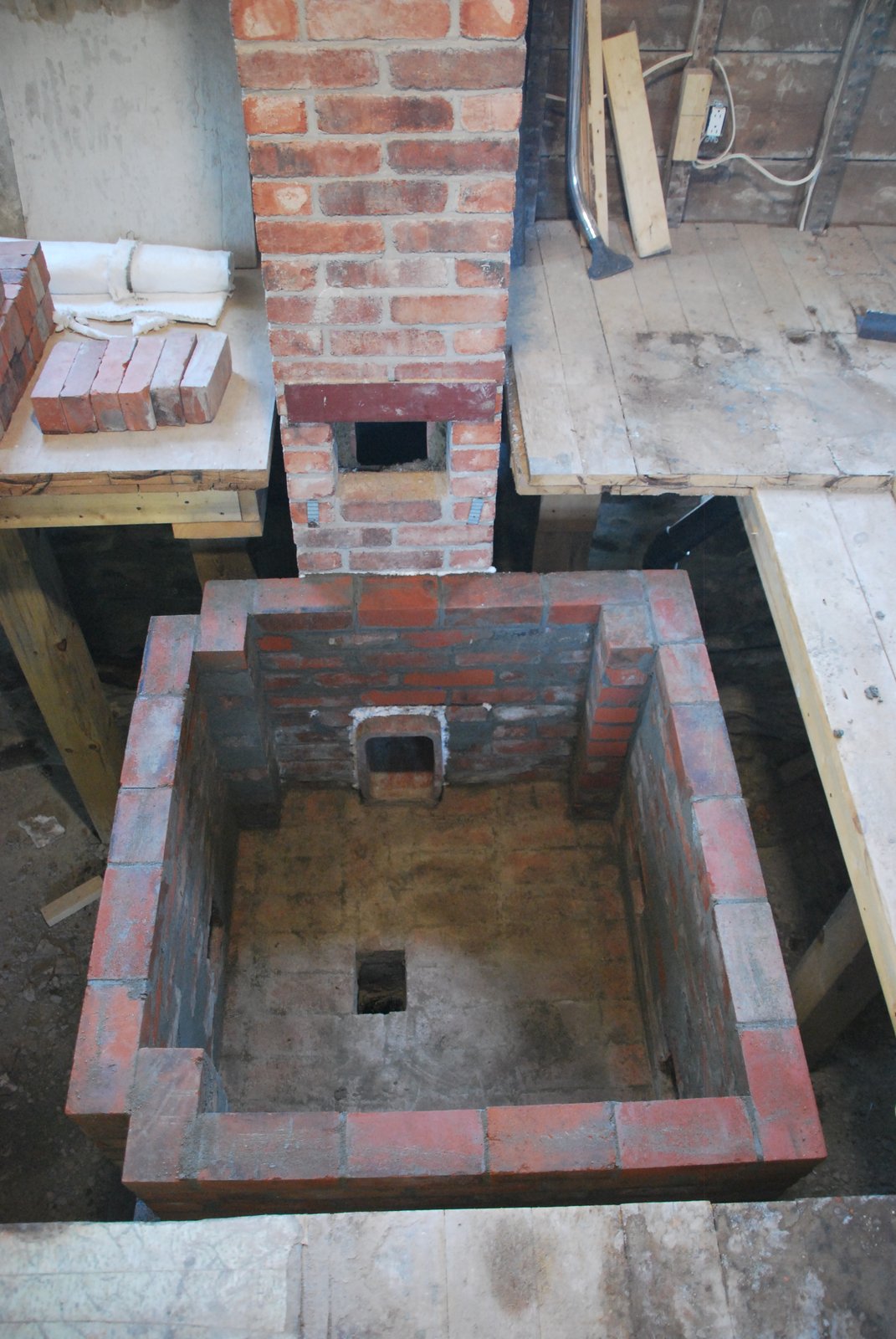
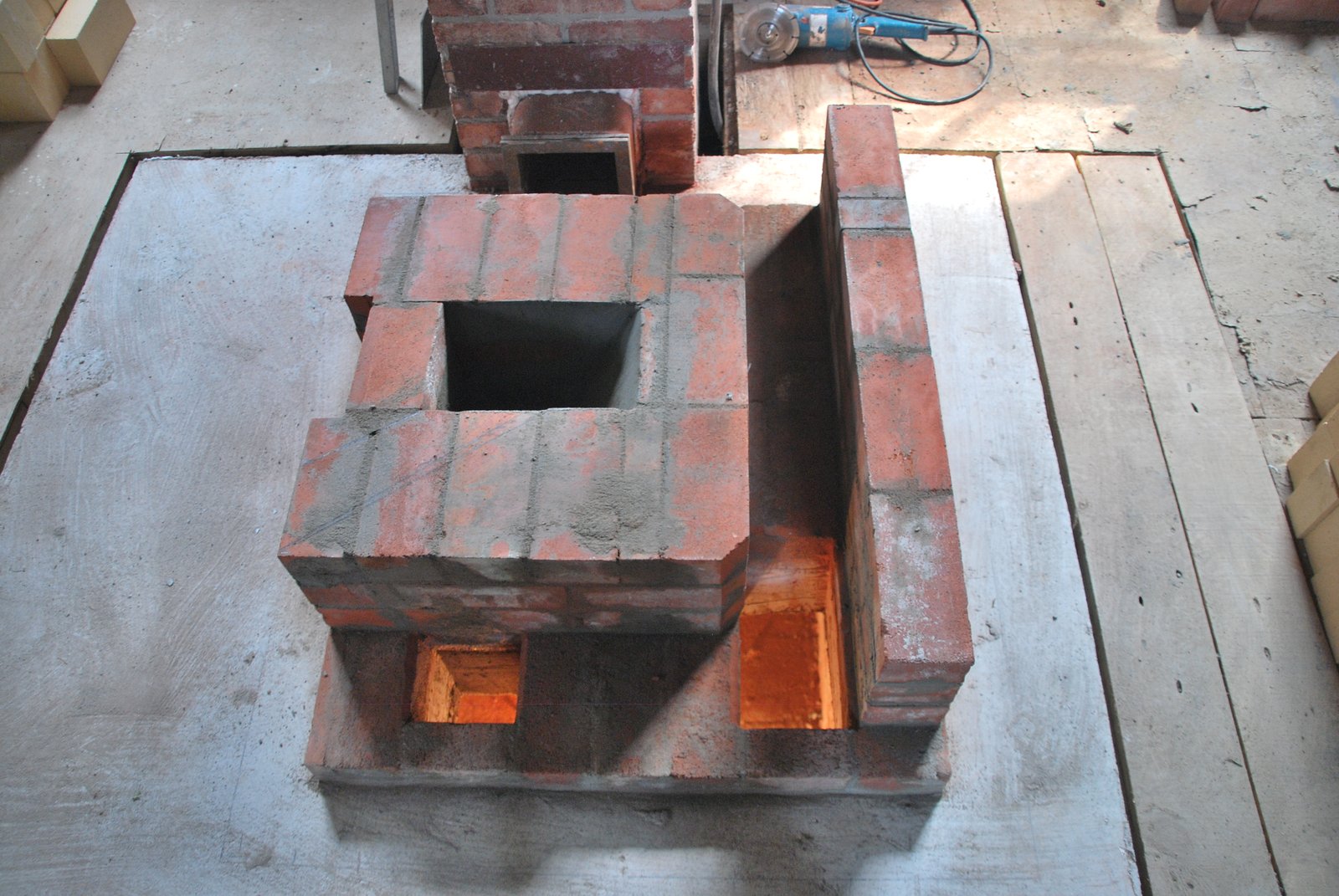
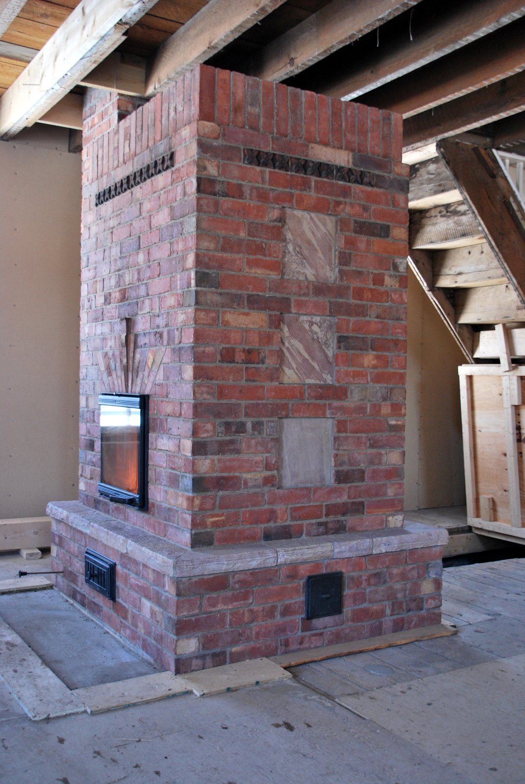
With the bypass open the stove will draw directly into the chimney. With the bypass closed the stove will draw down and through the bell before entering the chimney via the connection from the bell to the chimney.
The bypass was installed to avoid the risk of the bell not drawing, or drawing slowly, and to use during start up if necessary.
These variables are not always easy to predict so installing the bypass can potentially save a lot of trouble.
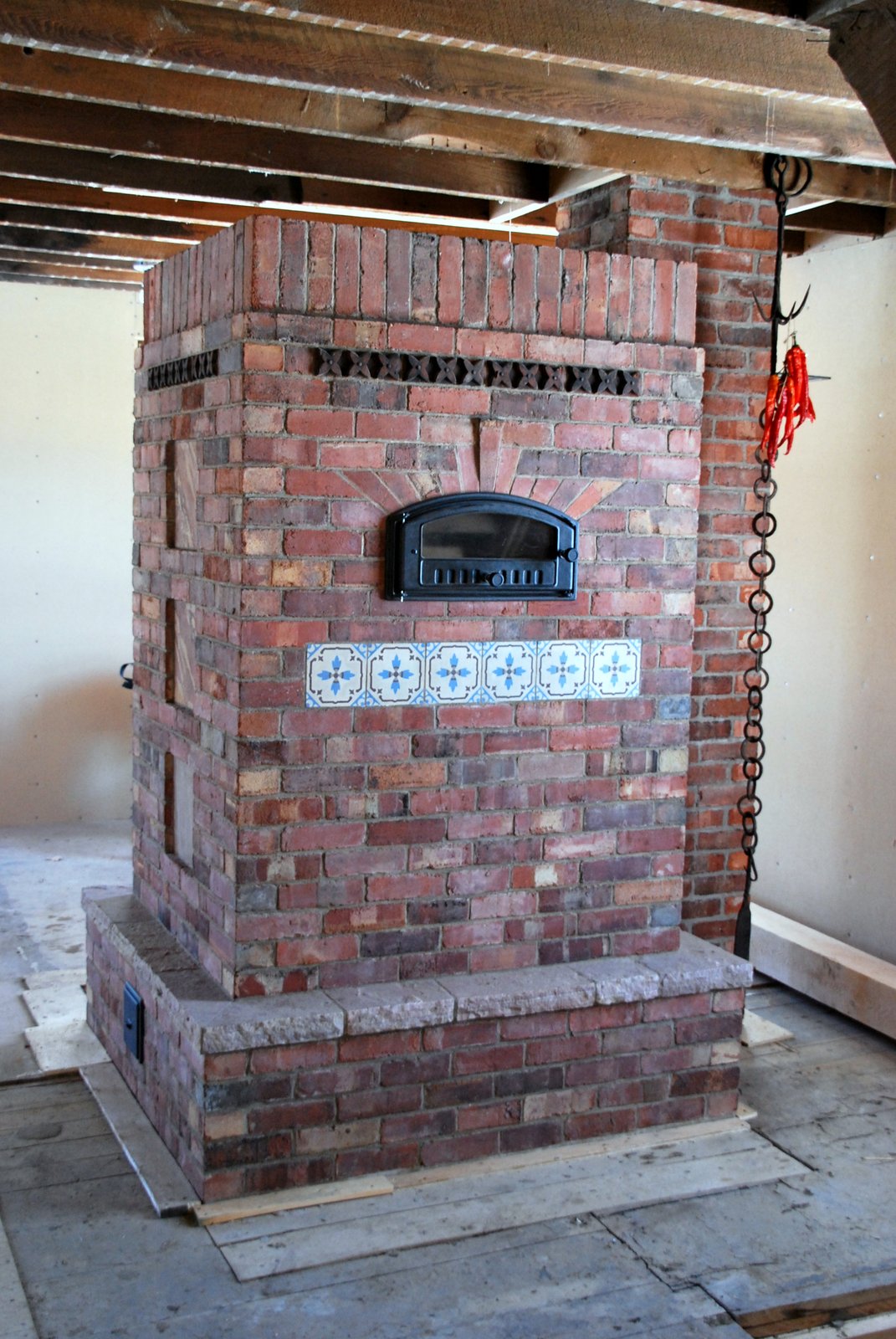
The stone Ducharmes Rose Arcenciel, Tiles c. 1910 are of Belgian origin.
Hardware by Upo.
Note the pull rod of the bypass is in the open position.
The fire can be started, with the bypass closed, i.e. bell engaged, if lit from the bottom. If the fire is lit from the top it burns better with the bypass open until it becomes well established. Once established the smoke will draw through the bell without problem and the bypass can be closed.
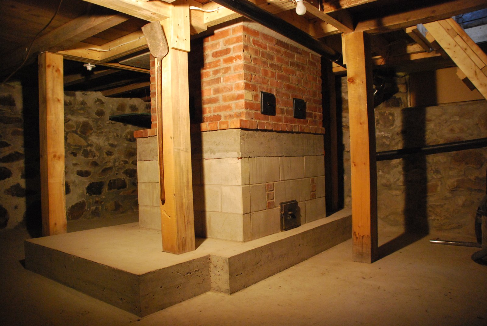
The walls of the bell and the slab on which the stove rests are relatively warm. The lower portions of the bells walls are cool.
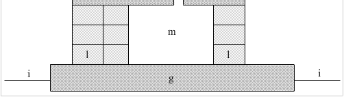
This is a simple extended smokepath, that has the same footprint as the heater and chimney, and can be incorporated into the upper portions of an otherwise void foundation.
The bell captures heat not absorbed by the stove, and so will never heat the basement as would a stove. It is though, a heat source in the basement , which combined with the ambient heat of the floors above, has so far kept the basement relatively warm and dry.
Marcus Flynn
2012
