Following is a description of the construction of a contraflow refractory core in the Massif des Bauges, Savoie France.
The challenge of this project would be the height limitation placed upon the heater by a particularly low ceiling.
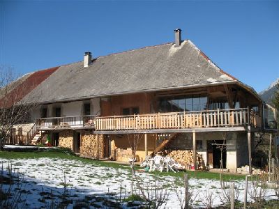
The heater would be located on the ground floor of a mid 16th century farm house typical of the region.
The core would be faced by the home owner.
Detailed are:
- Fire box floor without grate.
- The construction of a direct 'black' upper chamber oven.
- The construction of a transmission tunnel between core and chimney in the form of
a section of two tier extended smoke path.
- The construction of a bypass channel, connecting the core directly to chimney.
Materials
Refractory Brick
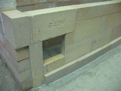
Bony B40N (French Format)
Refractory Mortar
Refracol 1
Castable Refractory Concrete
Refcast 1380 10
Ceramic Wool
Thermal Ceramics Super Wool.HT
The heater would be built in the area of the ground floor accessed by the open door at bottom right.
Though originally one farm, the building is now divided into two dwellings occupying equal halves of the rectangular structure.
The dwelling to be heated has ground floor walls of stone and upper floor walls of wood.
The view from the work station.
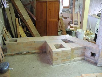
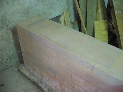
The base course of the core and bench are layed in common brick, in this case 'Leopard ' and type N mortar.
Leopard brick are made from a clay naturally rich in Kaolin and so have slightly superior refractory properties to many other clay brick.
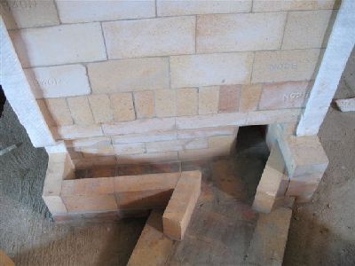
The fire box floor before the skew cut brick of the first course of the fire box walls are layed.
The pencil line shows the inner limit of the first course of the fire box walls.
Note the bond of the course seen here in relation to the pencil line. Each brick in this course will be held in place by the first course of the fire box walls, and therefore the full weight of the core.
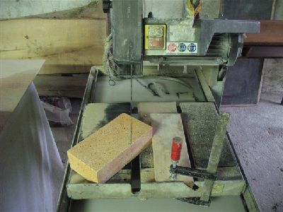
The cutting of the angled brick of the first course of the fire box walls.
A clamp and section of wooden plank are used as a guide as the original guide of this hired saw has been lost.
The marked brick is aligned with the blade, its bottom corner touching the fence.
Then the improvised guide is positioned against the top corner and tightened.
A pencil line (arrow) marks the position of the bottom corner where it touches the fence.
If sharp cornered brick are used , a series of perfectly identically cut brick can be
cut fast by aligning the bottom corner of each brick with the pencil mark, and
making sure the top corner touches the guide. Placing of each brick on the table
should be done gently as if the guide is knocked slightly out of position each
time a brick is placed, the angle of the cut will wander slightly through the series of brick cut.
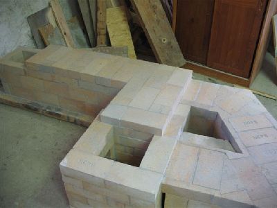
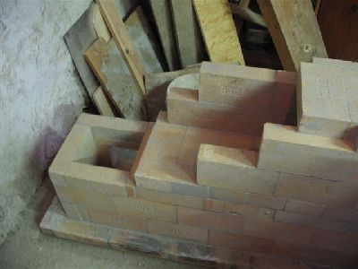
The fire box floor and first course of the fire box walls.
As there is no grate, ashes will be shovelled directly out of the fire box floor.
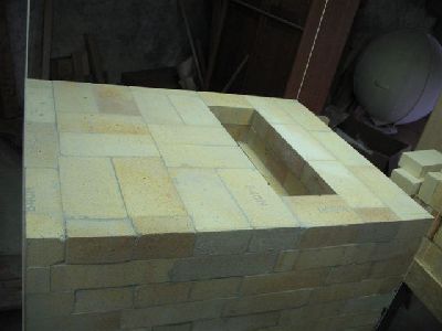
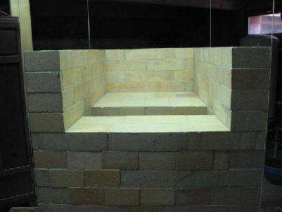
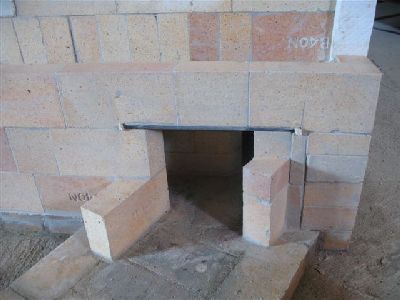
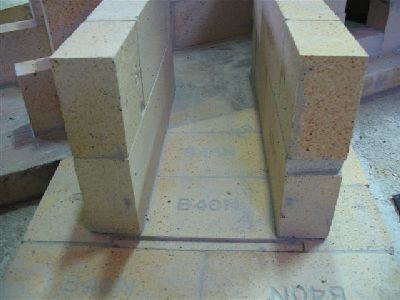
The oven hearth and in-flow throat at 15 cm. wide.
The core is 92 cm deep. The throat being 34 cm away from the oven door i.e. 23 cm of refractory brick and 11 cm of facing brick and backfill.
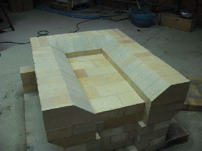
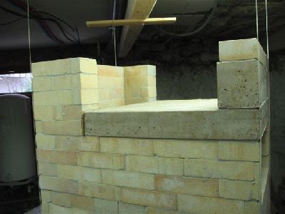
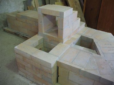
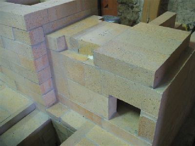
The side and rear walls of the oven.
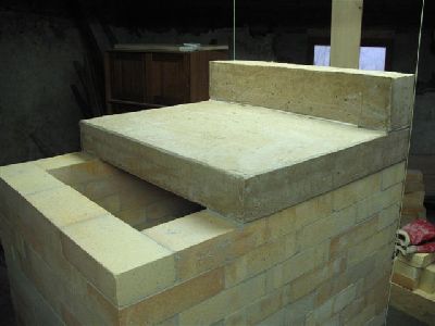
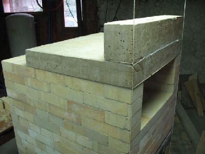
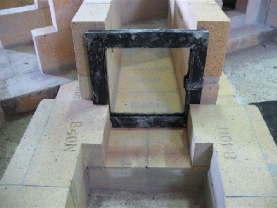
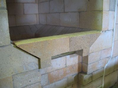
The oven slab and load relieving lintel seen from the rear. At 15 cm the out-flow opening is the same with as the in-flow.
The slab and lintel from the front.
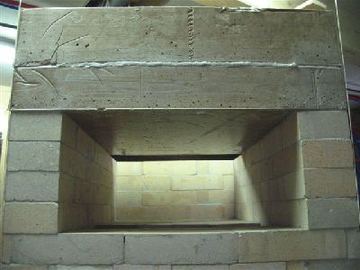
The direct oven was built due to the severe limitation on height.
An indirect, or white oven, would have taken up two more courses with its hearth slab and under hearth channel.
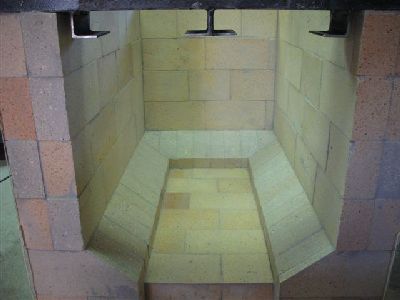
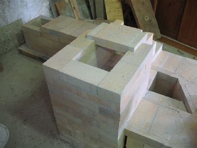
The rear wall of the core at maximum height 21.5 cm higher than the top of the oven slab.
The rear wall is separated from the oven slab by a cardboard gasket which is removed after the wall has been layed.
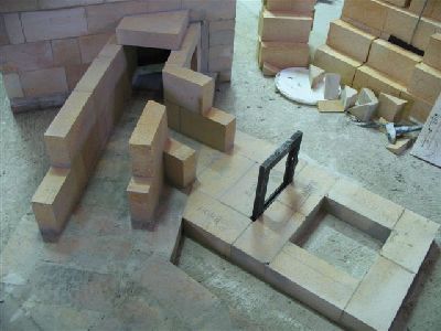
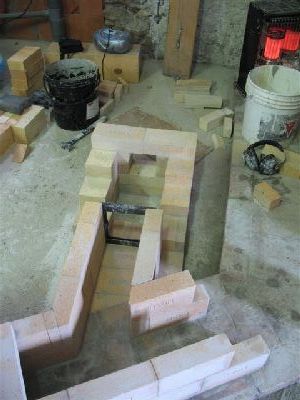
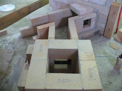
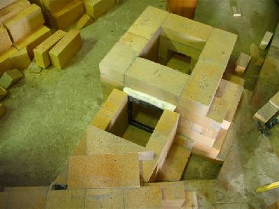
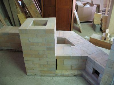
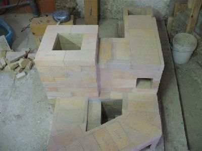
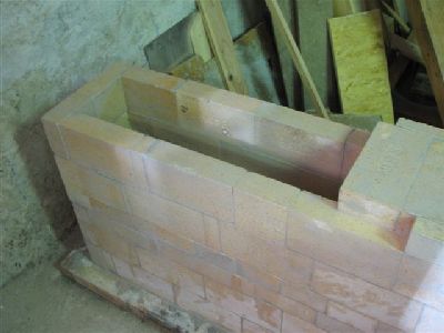
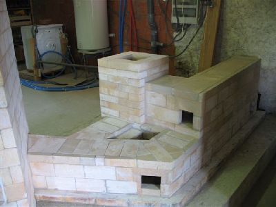
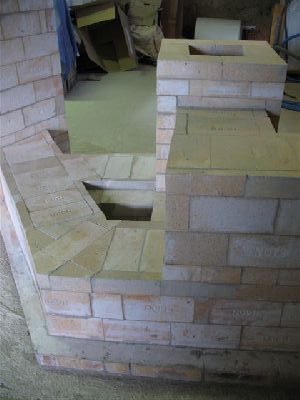
The finished core before construction of the side channels.
The left side channel as it bridges on though the rear manifold wall.
Due to a miscalculation the channel was slightly wider than the room available
on the base course of common brick. Pieces of scrap refractory brick were used to support the overhanging channel.
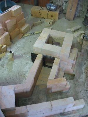
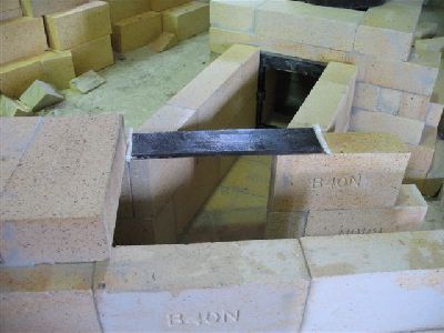
The right side channel and its exit opening into the tunnel.
The opening in the right side channel is bridged with a piece of 6 mm thick flat bar.
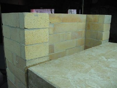
Though the inside dimension of the bench is only 19 cm and the brick 22 cm long,
the angle at which the tunnel joins the side channel makes bridging the opening with a full brick a weaker option than with flat bar.
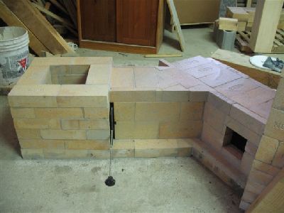
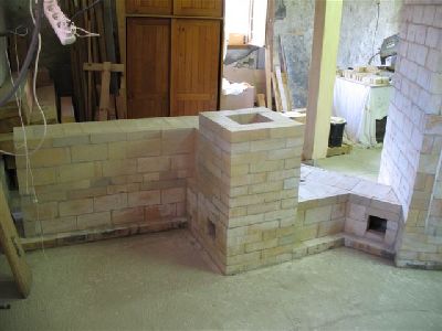
Lay out of the bypass channel from the tunnel to the chimney. A Pisla Oy 15 cm square shut off damper is used as a bypass control.
The interior dimension of the chimney is 22 cm square.
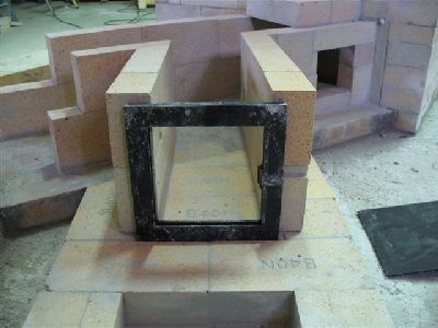
The bypass damper frame in position.
The recess in the base course accommodates the bypass dampers frame, and helps hold it in position.
The cut out in the top of the first course of brick on the right is to accommodate the bulge in the frame around the control rod.
The second course of the chimney is layed against the bypass dampers frame.
The manner in which the brick to the left is cut helps stop the frame being pushed out of place when the damper is closed.
The bypass damper frame is firmly held in place between the channel and the chimney walls.
The bridging of the bypass channel opening into the chimney.
The damper plate is inserted to assure a free action, before proceeding.
The bypass opening into the chimney.
The junction between the bypass channel and the tunnel is spanned by apiece of 6 mm flat bar.
Each end of the flat bar lintel is gasketed to accommodate expansion along its length.
The capping brick resting on the bar are cut out at the point at which they
contact the bar, to maintain a level surface along the top of the tunnel.
The lintel is half covered by the tunnels' capping bricks.
The first capping brick of the bypass channel is also cut out on its underside to accommodate the thickness of the flat bar lintel.
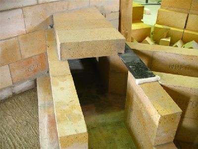
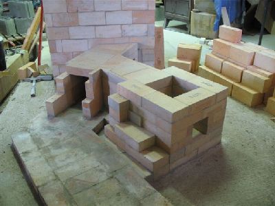
The completed first section of tunnel and the bypass channel.
The tunnel will bend at approximately 45 degrees just after the bypass channel.
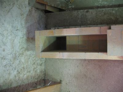
The tunnel before laying of the capping brick.
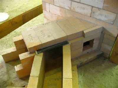
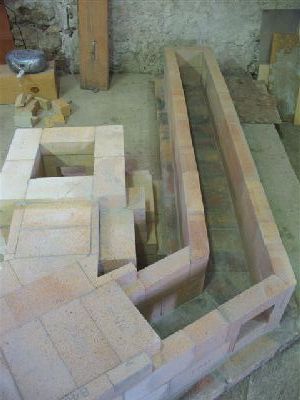
The completed lower tier of the tunnel.
The gasses will be drawn up through the opening at the end of the tunnel
into an upper section of smoke path before being drawn back into the chimney.
A course of brick is layed on the bench capping brick to provide a stable platform for the upper tier of the tunnel.
The exit opening, into the chimney, of the upper tier of the tunnel.
The chimney is built up around the tunnels exit opening.
The chimney back on format after bridging the tunnels exit opening.
View from behind the chimney after bridging the tunnels exit opening.
Closing of the 90 degree bend in the tunnels upper tier as it enters the chimney.
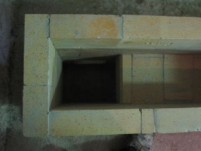
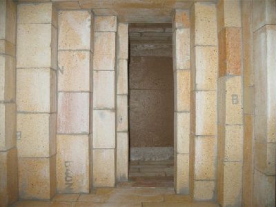
The upper tier of the tunnel, with inspection opening on the corner providing
access in a straight line down the full length of the tunnels' upper tier, as well as left into the chimney.
Construction of the walls of the tunnels' upper tier towards, the exit opening at the end of the lower section.
View from above of the upper tier before being closed with the capping bricks.
Detail of the opening between the lower and upper tiers of the tunnel.
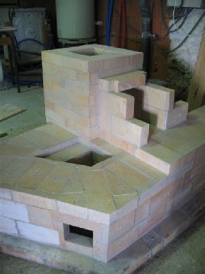
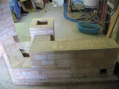
The completed two tier tunnel.
The finished section of two tier extended smoke path and bypass channel.
Seen from the back.
The inspection opening at the right gives access into the right manifold, and
the section of the tunnel (to the left) before the 45 degree bend in the lower tier.
The opening in the base of the chimney allows visual and physical inspection of the bypass damper.
The chimney will be continued in 230 mm round flue tiles that will rest upon the refractory brick base.
The void between the bypass channel and the 45 degree bend in the tunnel
will be filled with concrete and act as a support pillar for the final concrete pore over the tunnel once it has been faced.
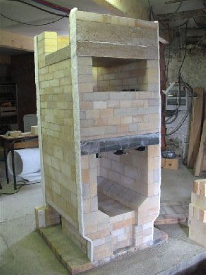
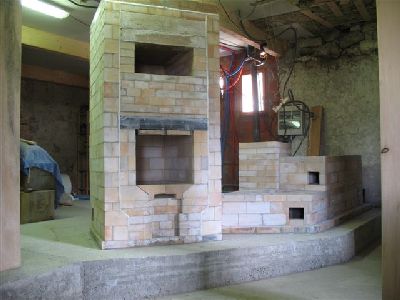
The core ready to be faced.
The primary air deflectors at the front of the fire box.
View up through the fire box towards the capping slabs. The fire box loading opening is to the right.
Update: Once faced the stove was first lit one year later with a series of priming fires. Even through the bypass, the first three fires were smokey, due to the exterior air temperature, and the humidity within the stove. It was a hot July afternoon.
The following morning at dawn, when the exterior temperature would be at its lowest, a fire was lit that took immediately without smoking at all. The bypass trap was closed and the gasses forced through the section of extended smoke path, with no noticable loss of draw.
The stove was fired twice per day for three consecutive days, at various times of the day. Never was it necessary to open the bypass trap, the stove drawing vigorously through the extended smoke path with no spillage at all.
The stove is conected to 8 metres of 200mm insulated prefabricated chimney, with one 45° elbow at 6 metres.
August 2009