Notes From The End Of The Earth: Finistere 2008
These notes detail the construction of a contra-flow heater in the principal building
of a derelict farm in the Department of Finistere.
The heater would be built in the living area against a load bearing wall,
which had been opened up from the kitchen to give access to an opening
(for an upper chamber oven) in the rear facing of the heater.
The rear wall of the heater will also radiate directly in to the otherwise closed kitchen.
Due to the difference in level between the living area and the kitchen the heater will be high.
This is to keep the oven loading opening at a reasonable height from the kitchen floor,
and to permit the core to protrude up onto the upper floor.
It coincidentally gives lots of room for the bench to pass beneath the fire box door.
Detailed are:
- the construction of a Refractory brick transfer tunnel or "bench" which will run round three sides of the heater
- the installation of a cast iron bypass channel
- the installation of the refractory caping slabs
- the pouring of the common concrete slab above
- the cutting of the primary air deflectors
The brick facing will be finished in earth rendering, using locally acquired sand, clay, and animal hair.
Materials
Refractory Brick
Bony B40N
Wool
Thermal Ceramics Super wool
Flue Tile
Terracotta 230 mm round
Flexible flue liner
Stainless Steel 230mm
Castable Refractory Concrete
Refcast 1380 10
See Technical Documents PDF Index
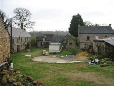
One of three farms forming the hamlet. I would be quartered in the trailer for
the 4 week duration of the project. The heater will be built in the building to the extreme left.
Nearby Ancient Oven
Local Neolithic Monument
The last original inhabitant of the hamlet recounts his lineage, in his mother tongue.
Taken in the kitchen of the house on the right in the above image.
Easter Sunday 2008 - (Video, 24 secs)
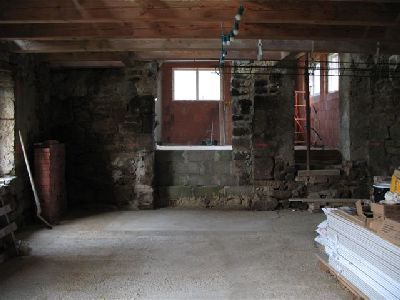
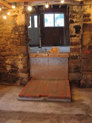
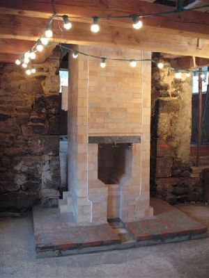
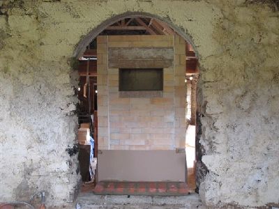
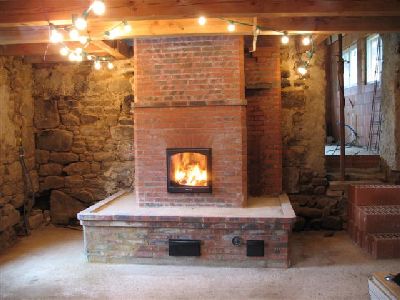
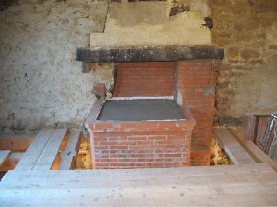
The main living area of the house. The heater would be located in the same position
as a recently demolished traditional open fireplace. The chimney will be in masonry
for the first 3 metres, changing to flexible stainless flue in order to exit through
the original stone chimney in the load bearing wall. Beyond the living room is the
kitchen, the floor of which is 1.4 m higher than that of the living area.
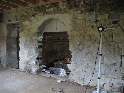
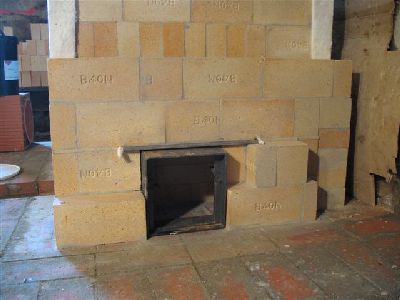
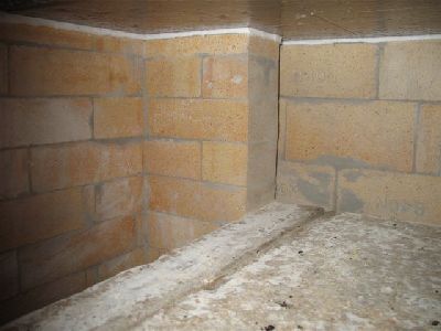
The kitchen and the opening in the load bearing wall, which will expose the rear facing of the heater.
The original masonry of this wall is layed in earth mortar. Superficial repairs have been made in lime mortar.
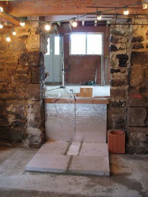
The existing wall behind the heater is insulated with two 3cm foil backed rigid
mineral wool panels. Giving 6 cm of Insulation.
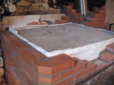
6 cm panels of Ytong cellular concrete are layed beneath the exact area of the heater,
including facing. The transmission tunnel will also rest upon a thermal break of
cellular concrete though it will be layed later to avoid walking over it during construction of the core.
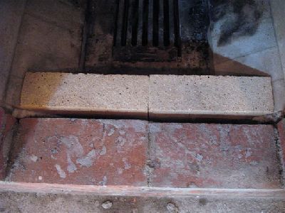
The first course of clay brick are layed on the Ytong.
The compressive resistance of this cellular concrete is 30 kg per cm2.
well in excess of the force exerted by the 6 tonnes of the heater.
The material is cheap, fire proof, easy to cut and lay, and provides a reasonable thermal break.
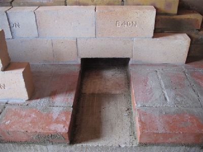
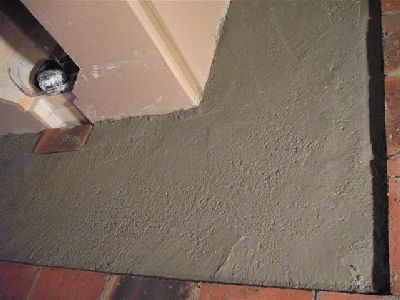
Note the colour difference between the common concrete footing, roughly the area to
be occupied by the bench, and the surrounding lime concrete slab.
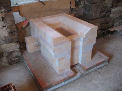
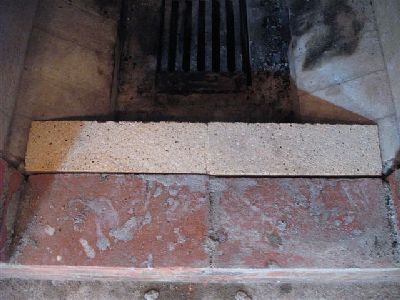
An additional two courses, one in the manifold and one in the fire box floor, raise the height of the fire box and thus the whole core.
The fire box consists of four courses of brick layed upon their side.
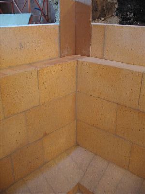
The cardboard gasket takes the place of a ceramic paper gasket, and allows
for expansion of the back corners of the inner wall.
The brick of the inner wall are not mortared to the outer wall, but will be held
firmly in place by an inevitable amount of squeeze out between the walls.
Detail of the cardboard expansion gasket on the corners between the two wythes of the wall
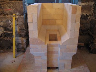
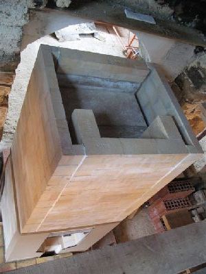
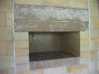
The completed fire box, before installation of the angle bar lintel.
The brick of both wythes at the front of the opening have been cut down 8 mm to recess the lintel.
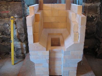
The first corbelled course of the baffle resting across three straight courses above the lintel.
View up through the fire box ceiling.
The baffle to the right. Note that the bottom of the ovens rear slab is not visible
in the throat. The capping slabs have not yet been installed.
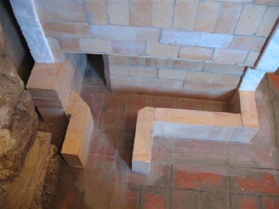
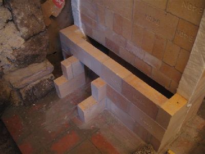
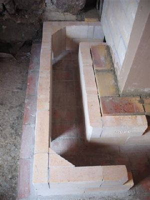
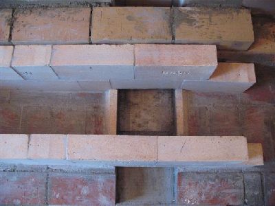
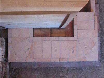
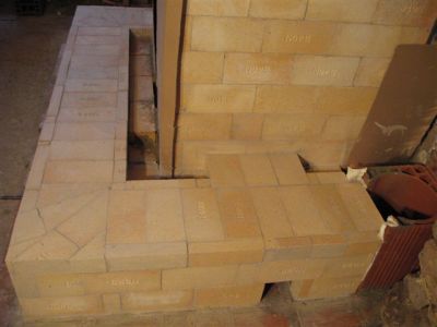
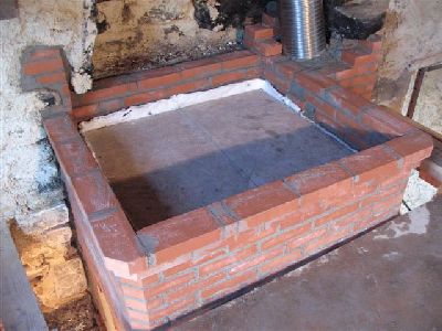
The completed core. Before laying the side channels the Ytong and base course of clay brick on which the bench will rest are layed.
The first course of the left side channel and its opening into the bench.
The width of the bench will be 19 cm. Its height 23 cm.
The second course of the channel and bench connection.
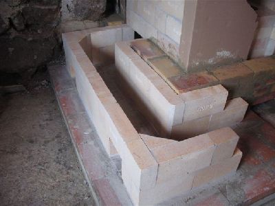
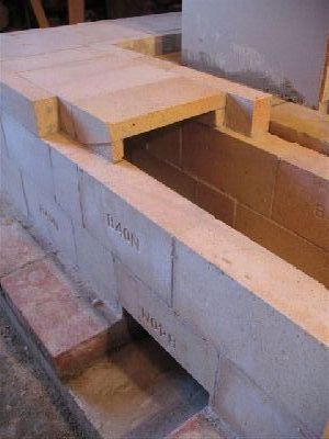
As the opening is only 19 cm wide it can be bridged by a single fire brick.
Bridging of the opening. Note the angled piece of brick layed over the protruding edge of the rear manifold wall.
When dealing with an extended smoke path all angled corners are best kept smooth to reduce the drag.
The channel will be layed up before continuing the bench.
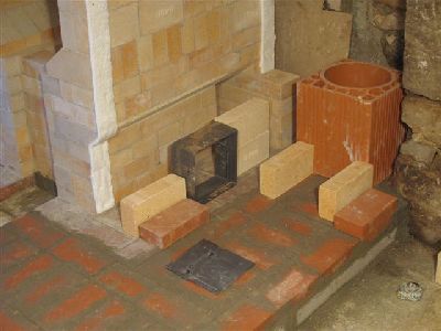
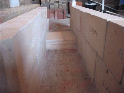
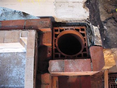
Dry lay out for the right side channel.
Before starting the channel, the walls of the bench and channel are layed out dry
in order to correctly position the bypass channel in relation to the flue tile.
Note: here the chimney flue tiles and facing rest upon the Ytong thermal break,
as the masonry portion of the chimney will be only 3.5 m high. It would be prudent
not to build a full masonry chimney on a thermal break of any kind.
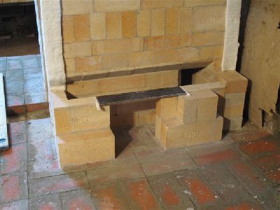
The opening for the bypass channel is slightly too wide to safely be spanned
by a single brick, and so a piece of 8 mm flat bar is employed.
The wall of the side channel is doubled each side of the opening in order to help
hold the bypass channel in place, and prevent disruption of the side channel
wall during repeated operation of the bypass control rod.
Gasketing of each end of the flat bar is important in this situation.
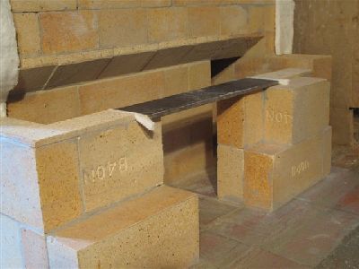
The area immediately surrounding the cast iron bypass channel and its transition
from side channel to bench to chimney, is an area of potential weakness, and
so work around it must be both strong and precise.
The cast iron bypass channel fits in to place with 3 mm play at the top and 0.5 mm
play on each side. As it would be removed, or moved frequently during the assembly of
the butterfly and operating handle, as it passed through the bench, no wool gasket
is employed around the channel.
The bypass channel is by Pisla Oy of Finland. The butterfly control rod will
exit from the right of the by-pass and traverse the bench in a steel sleeve, to an operating handle on the facing of the bench.
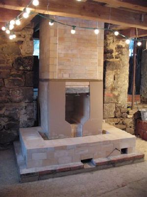
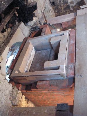
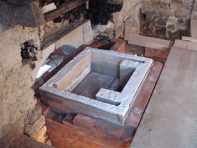
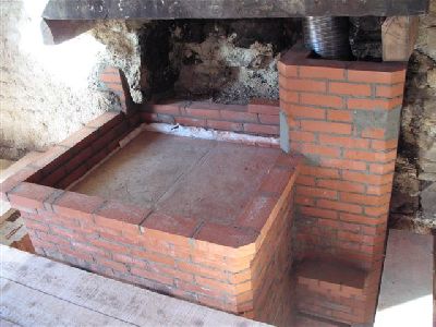
The finished core before construction of the bench.
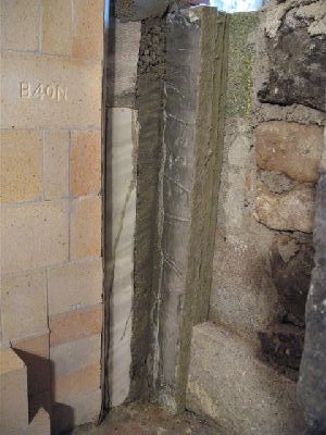
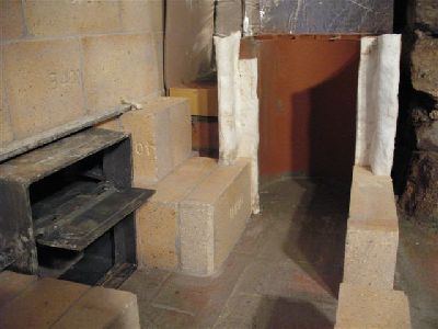
Before starting the bench, the space between the back of the core
and the wall below the floor of the kitchen is filled with material that
will insulate and provide enough compressing resistance to support the rear
facing of the core, above the kitchen floor.
Seen here from left to right. Cardboard expansion gasket, 7cm cellular
concrete panels, vermiculite concrete, and two sheets of 3cm foil
backed rigid rock wool.
View of the core from the upper floor.
The core seen from the kitchen.
The bench walls as it exits the left side channel. Note the three courses of
facing brick, which were layed up first around the heater to provide a stable
support for the back wall of the bench. It is these facing brick that will
support the concrete that is poured over the gasketed bench top.
There is no expansion joint between the benches rear wall and the facing of
the heater. Though a cardboard gasket will separate the benches front wall from its facing.
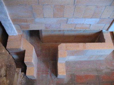
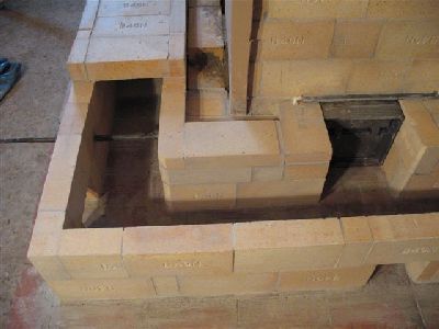
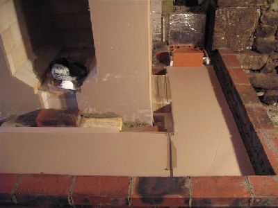
The opening at the back of the bench gives access to both rear and left manifolds
of the heater, as well as the left wing of the bench. The opening towards the front
corner gives straight access along the front portion of the bench.
The triangular pieces of brick in the outer corners of the bench slightly
reduce drag but primarily offer support for the capping brick which would not be
long enough to bridge the benches corners. A with of 9 cm is maintained at the corners.
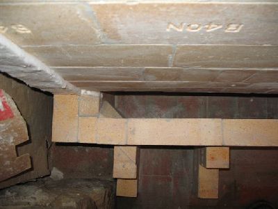
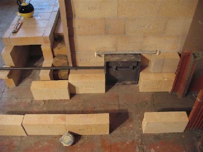
Primary air has to be drawn in under the bench.
This channel has to be high enough to allow cleaning access but not so high that it reduces the capacity of the tunnel.
The thin pieces of brick seen here increase the height of the primary air channel before it is closed.
The channel is closed with two courses of fire brick cut to about 1cm.
Two thin courses are used to ensure the joint between the two pieces forming the first course are covered.
In order that the capacity of the bench is restricted as little as possible, the capping brick
are cut out on the underside. This is done on the bricks just before, directly
above and just after the protrusion caused by the primary air channel.
The first and last brick of this recess in the capping bricks are cut back at an angle to avoid the drag of a sharp corner,
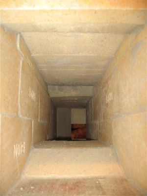
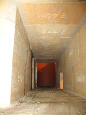
View down the tunnel, showing the bulge of the primary air channel and the
recess in the capping brick above.
The access opening on the left side corner of the bench can be seen in the background.
To the bottom right of the support pillar for the capping brick that traverse the corner.
An additional two slices of fire brick are layed over the lead and trailing
edge of the channel giving a shallower angle and so less disruption of the gases.
View from the upper floor.
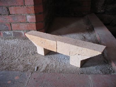
The two full brick cut to shape are used as primary air deflectors and heat shields in the front of the fire box.
The primary air deflectors in position, seen from inside the fire box.
A piece of flat bar will deflect the air as well, though the brick shield the otherwise exposed portion of the facing below the fire box door
Seen from outside the fire box, the brick deflectors are layed dry to allow
then to be removed thus facilitating ash removal from the primary channel below.
If mortared in place they would break loose after the first couple of fires.
If moved forwards slightly the deflectors allow an amount of secondary air
through the gap between them and the facing. This can also act as an air wash
over the glass of the fire box door.
Positioning the deflectors as shown though would only be of advantage if using a
door with no secondary air intake facility.
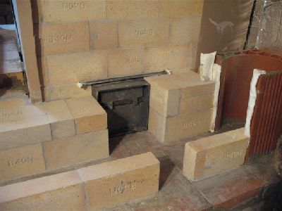
Capping brick over the first two corners of the bench.
The by-pass channel and its control rod in position. The square rod passes through the bench and the masonry in a steel sleeve.
The control rod is replaceable, access being through the access opening in the bench, directly in front of the by-pass channel.
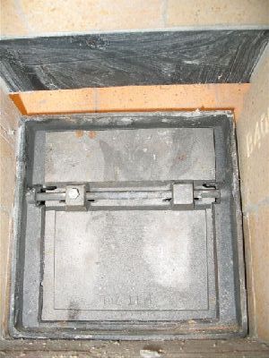
The bypass channel with the butterfly in open position.
The control rod and its sleeve are encased in the masonry to the left of the by-pass channel.
The masonry around the steel sleeve ensures that the cast iron channel does not wander due to repeated use.
The bench and bypass installation before the capping brick are layed.
An 8 mm piece of flat bar is used to negotiate the opening of the bypass channel.
The capping brick rest upon the gasketed lintel.
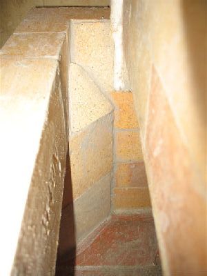
View along the interior of the bench towards the chimney, with the bypass opening to the left and access opening to right.
View of the bypass channel through the opposing access opening. Note the flat bar lintel used to support the capping brick.
The capping brick over the by pass and the benches third corner.
The capping brick are held in place by pieces of scrap brick cut to size.
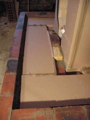
The completed bench, before facing.
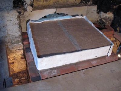
The bench gasketed with corrugated cardboard, ready for the concrete pour.
The concrete will only contact the clay brick of the heaters facing,
(inside of the bench) and the ledge formed by the double corbel of the
benches facing brick. The cardboard will prevent mechanical contact
between the capping brick of the bench and the concrete.
The facing of the bench has a cardboard gasket between it and the outer wall of the firebrick tunnel.
Fibreglass mat is preferable to cardboard but is not always readily available.
The concrete is poured and placed as quickly as possible to avoid,
or limit the collapse of the cardboard gasket before the concrete can harden.
The facing is layed up to just below the last course of the core.
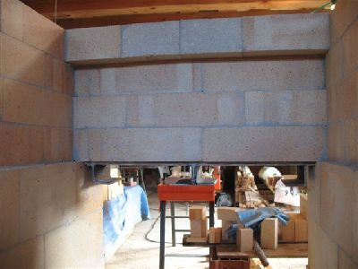
These images are taken on the upper floor of the dwelling, where 70 cm of the heaters total hight of 3 m will be visible.
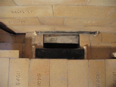
The last 230 mm clay flue tile, before the transition to 230 mm flexible stainless steel.
The tiles in this situation are gasketed with cardboard before being back filled.
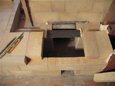
There are two sections of tile above the damper, their weight being necessary to hold the damper frame in place
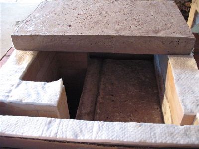
Before the two refractory concrete capping slabs are layed in place, all the
surfaces which they will contact are gasketed with wool. This acts as a smoke gasket
and a means of evenly distributing the weight of the capping slabs on what is
inevitably not a perfectly level surface.
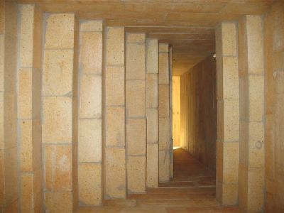
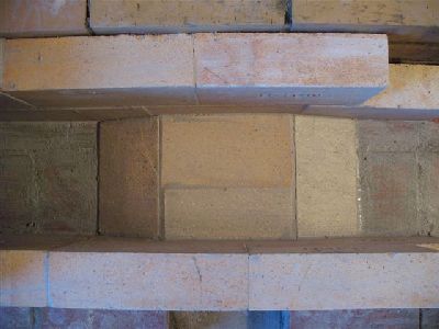
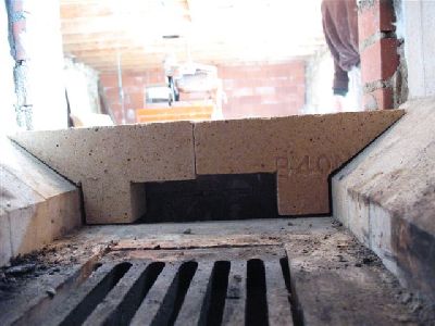
Note the two wings of the side walls of the fire tube. They throw the gases forward
over the oven and diminish the bridge of the two capping slabs. This last function
is important in this situation as the core at 92cm is much deeper than most contra-flow cores.
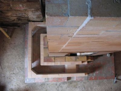
View beneath the fist slab, towards the fire tube, left and the left side channel, right.
The two coping slabs are mortared together, though this is probably superfluous as the slabs will inevitably separate.
The band of wool around the edges of the slabs protrudes down over the cardboard,
forming both a smoke and expansion gasket. The wool assures that if the cardboard
burns, smoke or flame will not spill out between the facing and the final
common concrete capping slab.
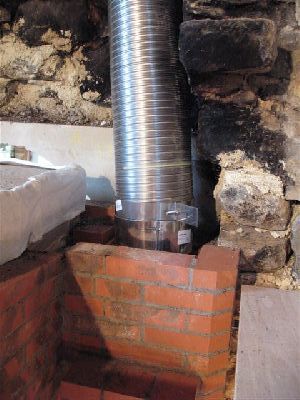
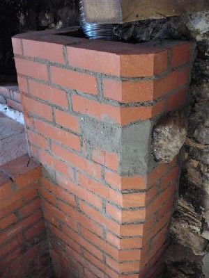
The transition collar, bottom, and flexible flue above. The support bracket around
the collar will be embedded in backfill, ensuring that the collar cannot be pulled up and out of the clay tile during sweeping of the chimney.
The facing as it is layed up around the gasketed capping slabs. Due to the thickness
of the wool and possible overhang of the capping slabs, the brick of these rows
may have to be cut back on their rear face to avoid having to bang them into
line against the gasket, causing a potential mechanical bridge.
The final course of the heaters facing, three courses higher than the top of the capping slabs.
The last two corbelled courses will provide ledges onto which the common concrete capping slab will rest.
The chimneys facing is layed almost to the avaloir of the original fire place.
This avaloire was over the fire place on the first floor, but was moved up
and out of the way before the project began.
Note. The corbelled ledge on the facing of the chimney is to support part of the
upper floor structure. This is illegal in North America.
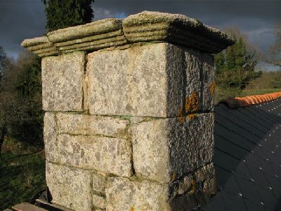
The granite chimney top of the existing chimney flue, to be used
by the flexible stainless steel liner.
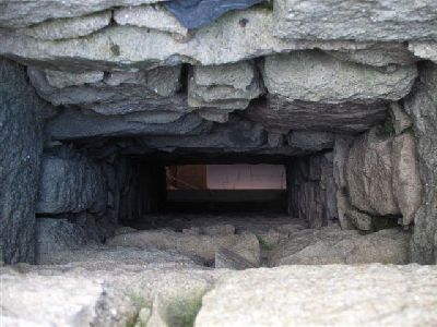
View down the original flue prior to the start of the project.
The chimneys facing is layed around a tie stone, which protrudes from the load
bearing wall maintaining the masonry of the avaloir above it.
Until the top of the heaters facing the chimney is faced on only two sides.
Though the chimney facing is tied into that of the heater, it is not that stable.
(Though up to this point it covers only the double skinned flue tiles,
which are to code without facing.)
Above the facing of the heater the chimneys facing is almost wrapped around the
stainless flue, being incomplete only at the back right corner.
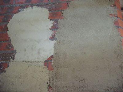
As the last portions of the chimneys facing are being finished, and the first
priming fires lit, test mixes of rendering containing different clays and sands are
applied to the facing in order to arrive at a suitable final recipe.
The space above the two refractory concrete capping slabs is lined with wool
and then poured with common concrete. This slab rests directly upon the ledges
created by the two last corbelled courses of facing brick.
The slab will be finished in slate from a near by quarry.
The heater is brought up to temperature and then allowed to cool before it is rendered.
The top of the heater protrudes 10 courses into the upper floor
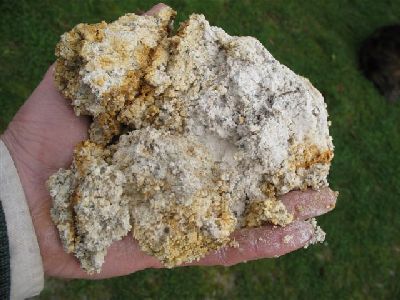
The final choice of clay to be used for the rendering, rich in kaolin and small feldspar crystals.
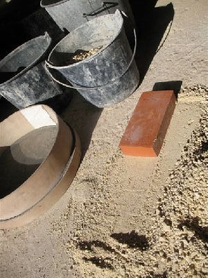
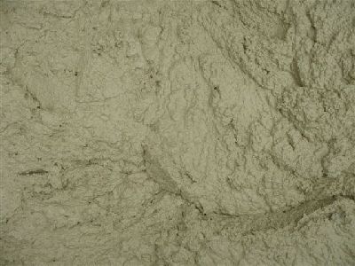
After being thoroughly dried the clay is ground to powder by rubbing it into the hard
concrete floor with a brick. It is then passed through a fine screen and
mixed with screened dry sand in the proportions of one clay to two sand. It
was decided finally that the addition of animal hair to the rendering mix
would be a superfluous complication.
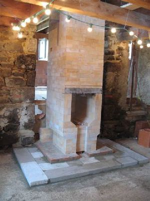
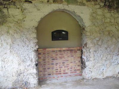
The back of the heater with the upper portion around the oven door rendered.
The clay brick of the lower portion of the facing are jointed in lime mortar and will remain visible.
A purely aesthetic choice of the clients.
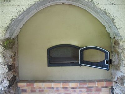
Detail of the rendering around the ovens loading door.
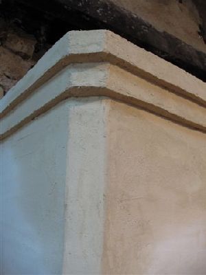
Detail of the rendered uper corbel of the heaters facade.
The remainder of the rendering and the laying of slate on the bench top and top of
the heater will be carried out by the client at a later date.
Images of the finished project will be added to this article when available.