Chimney Connection #8
These images and text detail certain stages in the construction of a North American variation of the Finnish Taaka in Dauphiné .
The stove will be connected to a remote chimney by a 1.75 M long section of horizontal extended smoke path. Around this transmission tunnel will be built ( by others) a masonry pavilion from which the dwellings principal stair case will rise.
The site was about 150m from a 10th Century earth works.
Materials
Refractory Brick
Bony B40N
HTC
Refracol #8
Castable Refractory Concrete
Refcast 14 60/10
Facing Brick
Leopard
Repro Antique Brick as trim.
Repro Antique Brick as trim.
Rendering
Sand Lime
Flue Liner Tiles
230 mm Round Terracotta
Ceramic Wool
Superwool 600
Glass Fibre Mat
450 g.
Common Mortar
Bastard 1 to 3. ( 20% cement 80% lime)
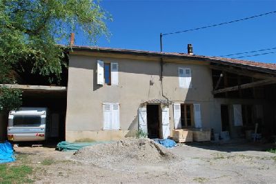
The heater would be built in the principal dwelling of an old tobacco farm on the Bièvre-Valloire plain.
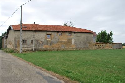
The back of the farm house. The heater will be located just in front of the existing chimney top. The house was built in 1880.
Both exterior and interior walls of the farm house are of pise.
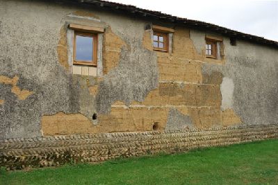
The pise (pressed earth) walls are built on to a knee wall of stones layed in a style called 'gallete pose en arret de poison' (fish bone bond)
Note: The horizontal white lines visible on the pise wall where the rendering has fallen away. These are thin beds of lime mortar that were layed between batches of pressed earth , to stop the corners of the wall crumbling away as the shuttering boards were removed and replaced higher up the wall.
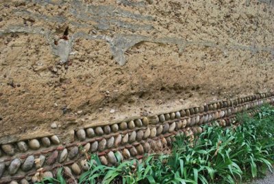
The graded stones are layed onto a bed formed from pieces of broken roof tile, placed above the head joints of the course below. These pieces of clay tile support the mortar bed of the following course.
The stones are part of medial moraine deposited by glaciers, throughout the region.
The wall of stone provides a solid bed for the pise wall, and prevents the pise from wicking up humidity from the ground.
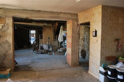
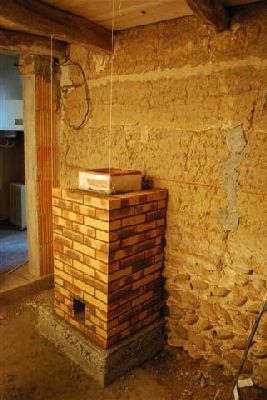
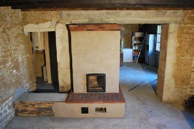
The location of the heater, seen from the living room. The oven will face this room and the fire box opening the kitchen.
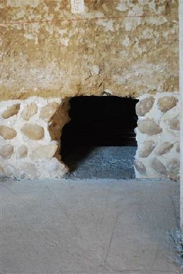
Detail of the opening through which will pass the transmission tunnel to the chimney on the other side if the wall.
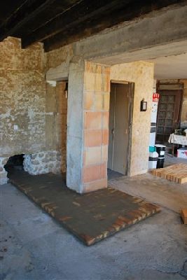
The first course of clay brick represents the footprint of the core and the transmission tunnel. This course is layed in common mortar.
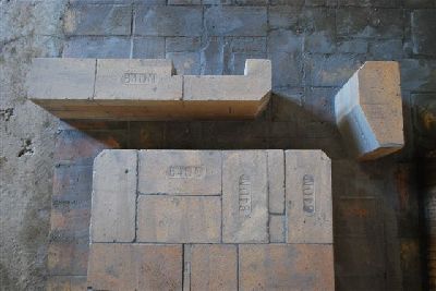
The first three courses of refractory brick at the rear manifold. Note the support pillar for the lintel that will bridge the opening in the manifold wall, and the primary air cut out on the outer face of the manifold wall.
A full length brick has been used as the support pillar as it is more stable than a pillar of half bricks.
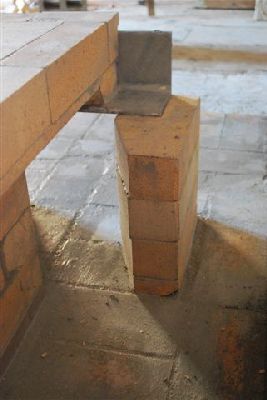
Extreme attention must be given to the work directly over the lintel and support pillar.
The exit opening in the manifold wall, bridged by a 10 x 10 x 1 cm angle iron lintel, and two subsequent courses of brick.
The opening is at this side of the manifold wall and not the opposite side, to reduce the length of the transmission tunnel. It also allows primary air to be be taken in directly through the facing rather than having to be channelled beneath the tunnel.
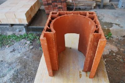
The first angled course of the fire box walls.
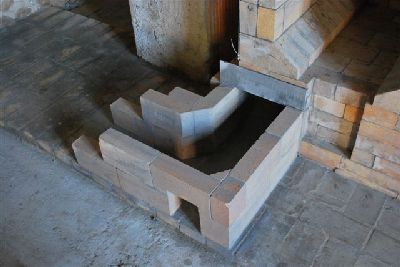
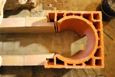
The start of the transmission tunnel .The 90 degree bend is eased, by removing, and filling,the two corners.
The small opening allows access to the tunnels connection, rear, and left manifolds.
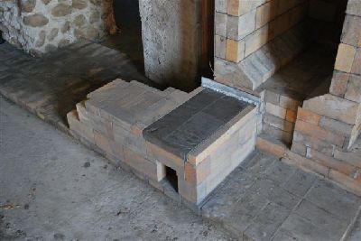
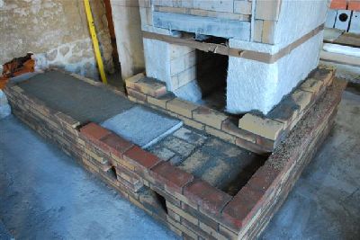
The tunnel is capped, above the bend, with a refractory concrete slab poured to size the previous day. Capping the tunnel at this point, in brick would have been time consuming, and weaker than the slab used.
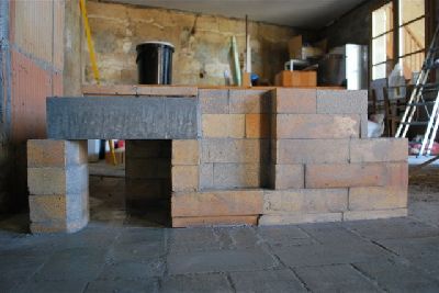
The completed tunnel.
The primary air intake channel is relatively large, to enable the removal of ash
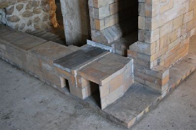
The capping of the primary air channel.
Had the tunnel exited from the right manifold and flowed across the whole front of the stove, the introduction of primary air would have been through a channel running beneath the smoke path of the tunnel This would necessitate a thin channel, below the level of the primary air intake door, which would be difficult to clear of ash, that would inevitably fall down into the channel.
In this situation, there is limited height between the base course and the finished top of the tunnel making an under tunnel air intake impractical.
Also the tunnel at 1.75m is long enough without gaining the extra half metre by crossing the whole front face of stove.
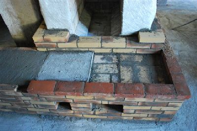
The right side channel is straight forward, having only a manifold access opening.
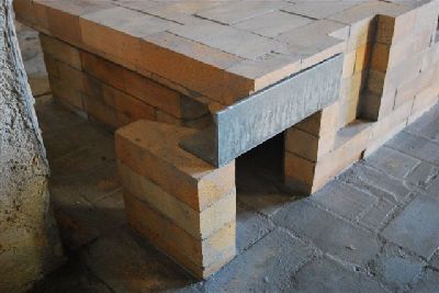
The left side channel must rest upon the brick support column and the angle bar lintel which rests upon it.
The exposed sharp corners of the column in the smoke path are filled with angled pieces of brick to reduce drag .
As with all the work around the support column, great care must be taken with this portion of the side channel.
View of the left channel as it courses over the support column and lintel.
The angle bar lintel must have sufficient lateral gasketing to prevent it pushing the side channel out of place on the support column
The reinforced concrete footing on to which will be built the chimney.
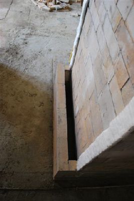
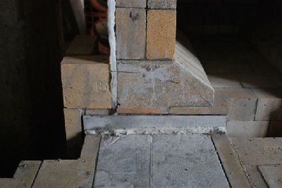
Cross section of the top of the tunnel as it traverses the wall. Note that the last two courses of facing brick are cut back to provide a flat surface on the facing to each side of the refractory brick portion of the tunnel.
This allows the concrete, poured onto the upper surface of the tunnel , to bridge onto the facing and not rest at all upon the refractory brick.
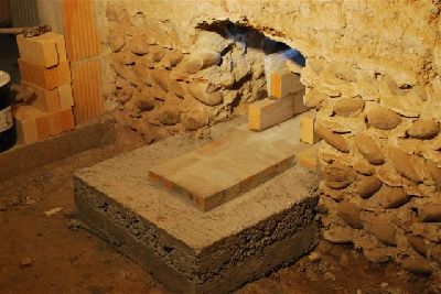
The top and sides of the tunnel are gasketed with two sheets of glass fiber matt.
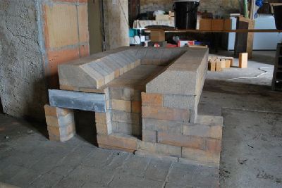
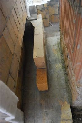
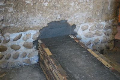
The concrete poured onto the tunnel is thick enough to support the masonry pavilion of the stairway that will rest upon it. The tunnel is capped with refractory brick splits, in order to reduce its overall height.
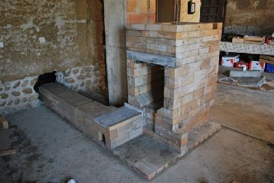
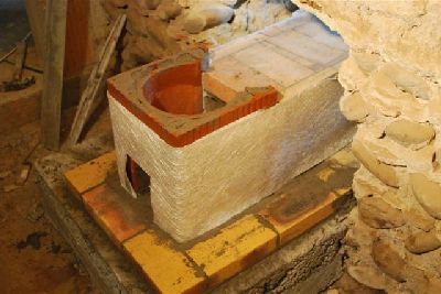
The completed core and transmission tunnel before facing.
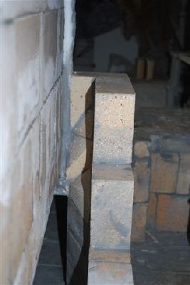
The first flue tile is temporarily placed in position before being gasketed with ceramic wool at its juncture with the refractory brick, and layed in common mortar.
Detail of the flue tile after being cut to accept the side walls of the transmission tunnel.
The tile is gasketed with two sheets of glass matt before the facing is layed.
The voids of the first flue tile are filled with mortar to solidify the tile which has been weakened by the cuts. Subsequent tiles can be filled with mortar or dry sand to increase thermal transmission through the wall of the chimney.
The void between the tile and the rear surface of the brick is also filled with mortar to assist thermal transmission.
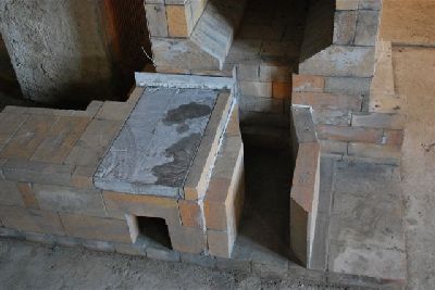
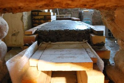
The refractory brick portion of the tunnel directly above its connection to the stove is bridged by a refractory concrete slab, originally poured for the ovens heart, but disregarded due to imperfections on the cold surface. This slab rests upon the facing and the wall of the primary air intake channel, allowing the tunnel beneath to move freely.
The portion of the tunnel directly in front of the heater will be finished in facing brick, layed directly upon the masonry seen here.
Once the tunnel had traversed the opening a concrete lintel was poured to maintain the pise wall above.
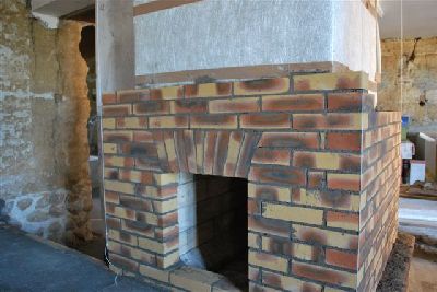
The arches in the facing are cut by eye, as aesthetic precision is not an issue. They are easy to build and by principal cannot fail.
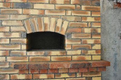
To cut and lay the springers, then the voussoirs, and finally cut and lay the spandrels, takes about an hour.
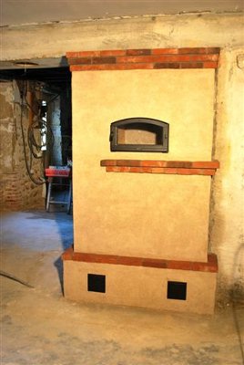
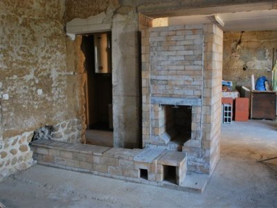
The facing is rendered before the hardware is installed.
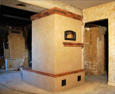
The transmission tunnel to the left will be enveloped by a masonry pavilion from which will run the main staircase up to the first floor, and two steps down through the doorway, to the left of the heater, to the bathroom.
Marcus Flynn
Montreal 2009
