The article illustrates the connection of a see-through contra-flow masonry heater to a remote existing chimney flue, via a custom transmission tunnel.
The transmission tunnel would be 2 metres long and feed in to a vertical flue with a total height of 5 meters. Due to the heater being remote from the chimney there was no possibility of installing a bypass channel.
Materials
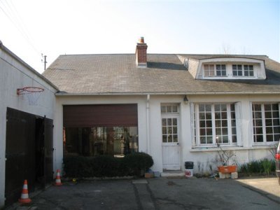
The dwelling was built in the early 1950 in a town completely destroyed during Operation Overlord.
The existing chimney at 5m is relatively low.
The reinforced concrete footing of the heater and transmission tunnel.
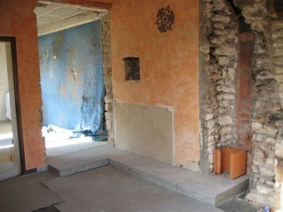
The wall to the left has been opened to accommodate the heater, and an existing
open fireplace removed, at right. The back of the demolished original clay lining
tiles can be seen mortared in to the stone work of the load bearing wall above
the new 230mm clay flue tile.
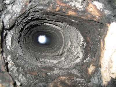
View up through the original 200mm oval flue.
In the chimney's 5m vertical flue there will be four changes of format.
230mm clay liner, 200mm round Stainless liner, the 200mm oval flue section shown,
and 200mm round pot on the roof.
Obviously this kind of variation in flue format and capacity should be avoided when ever possible.
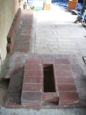
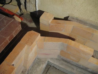
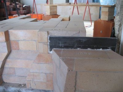
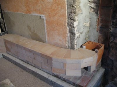
The first three courses of the core and the base course of the bench.
The base course of both bench and core are layed in Type N mortar, the two rows of the core in HTC.
Note the two shiner courses layed up against the wall.
This will act as support for the concrete poured over the tunnel once the facing has been brought up to height.
They have been layed at this point so that the refractory brick of the tunnels rear wall can be layed directly against them.
The tunnel exits the wall of the rear manifold at a diagonal angle to leave
room for the portion of the manifold wall that will act as a support column for
the lintel that will span the opening.
Note the cross bonding between the two courses of brick forming the tunnel wall as it bends back in to line.
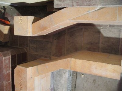
Overhead view of the bend as the tunnel exits the rear manifold wall.
The capping brick of the tunnel over the bend as it leaves the rear manifold.
The tunnel is 19cm wide by 23cm high. The capping brick being only 23cm long have
only 2cm resting on each of the side walls.
The backing pieces of brick assure the capping brick remain in place, and provide
a square finish to the top of the tunnel.
This makes gasketing of the tunnel, before concrete is poured over it, much easier and effective.
A piece of 8mm angle bar is used to bridge the opening in the rear manifold wall.
The first two courses of the core layed over the lintel. The diagonal chase to
the left allows primary air to be drawn up between the facing and core.
As the heater will have a fire box opening in both rear and front faces there
needs to be a primary air intake channel in both faces.
Intake of primary air from only one face would result in the flame and smoke being
blown onto the opposing door. The chase is angled to allow the primary air intake
door to be offset from the centre of the facing of the heater in order
to avoid the facing of the tunnel.
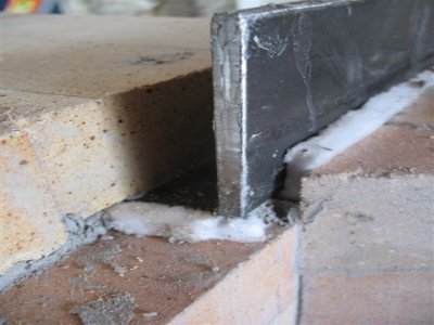
Detail of gasketing around the angle bar lintel. The ceramic wool against the
end acts as an expansion gasket, the wool along the back of the bar, a smoke gasket
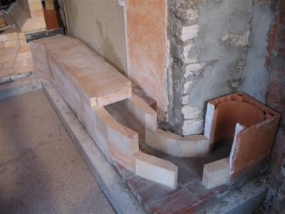
The almost completed tunnel as it curves towards the first flue tile. A curve
has been used here as it will cause less resistance than a rounded right angle corner.
The difference between the two is slight, but with a tunnel this long, and chimney
of only 5m, it is best to impede the draw as little as possible.
Cross bonding on the curved walls of the tunnel.
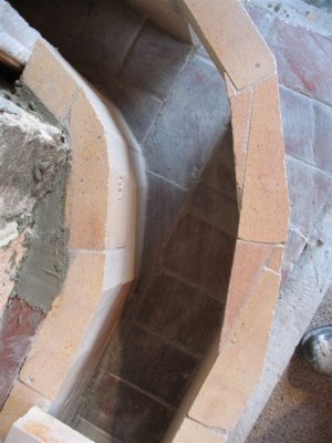
Detail of the bonding on the curve.
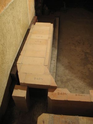
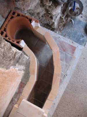
The completed tunnel.
The opening on the curve gives access down the tunnel into the right manifold of the core
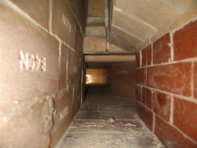
View from the manifold access opening in the front of the core along the manifold
through the tunnel to its access opening on the curve 3m away.
Note the angle bar lintle bridging the opening.
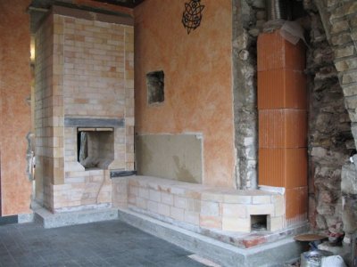
The finished core. The flue tiles have been dry stacked, and a section of 180mm
flexible stainless steel pipe temporarily installed, in order to test the draw.
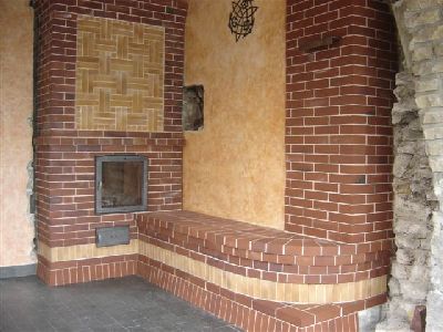
The core faced by the home owner in artisanal coal fired brick.
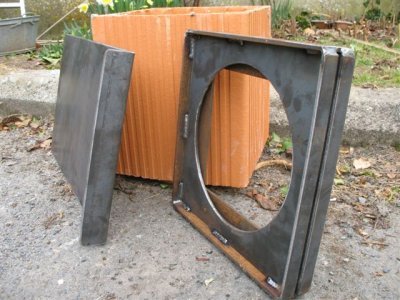
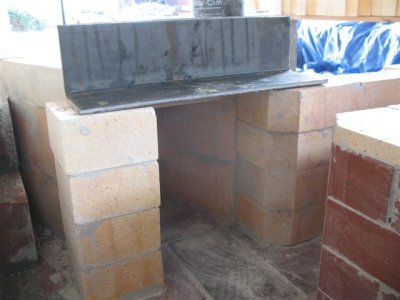
The two elements of the guillotined shut off damper, custom made from 6mm mild steel.
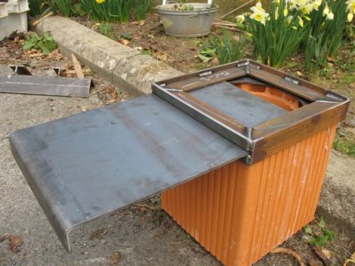
The damper frame and plate set in position on a clay flue tile.
Marcus Flynn
Montreal 2008
