These notes and images outline the installation of a North American Contraflow stove and its chimney in the Sorel Islands Quebec.
Detailed are: The setup of the see-through fire box, and construction of the chimney using rigid stainless steel flue liner.
Materials:
Refractory Mortar
Mount Savage Super High Mull
Castable Refractory Concrete
Mount savages Heatcrete 421 esc
Ceramic Wool
Thermal Ceramics. Soluble
Ceramic Paper
Vesuvius Rollboard
Facing Brick
Recycled dense solid burnt clay c.1900.
Facing Mortar
King 116 Type N
Flue Liner
Exel type 304 stainless Steel.
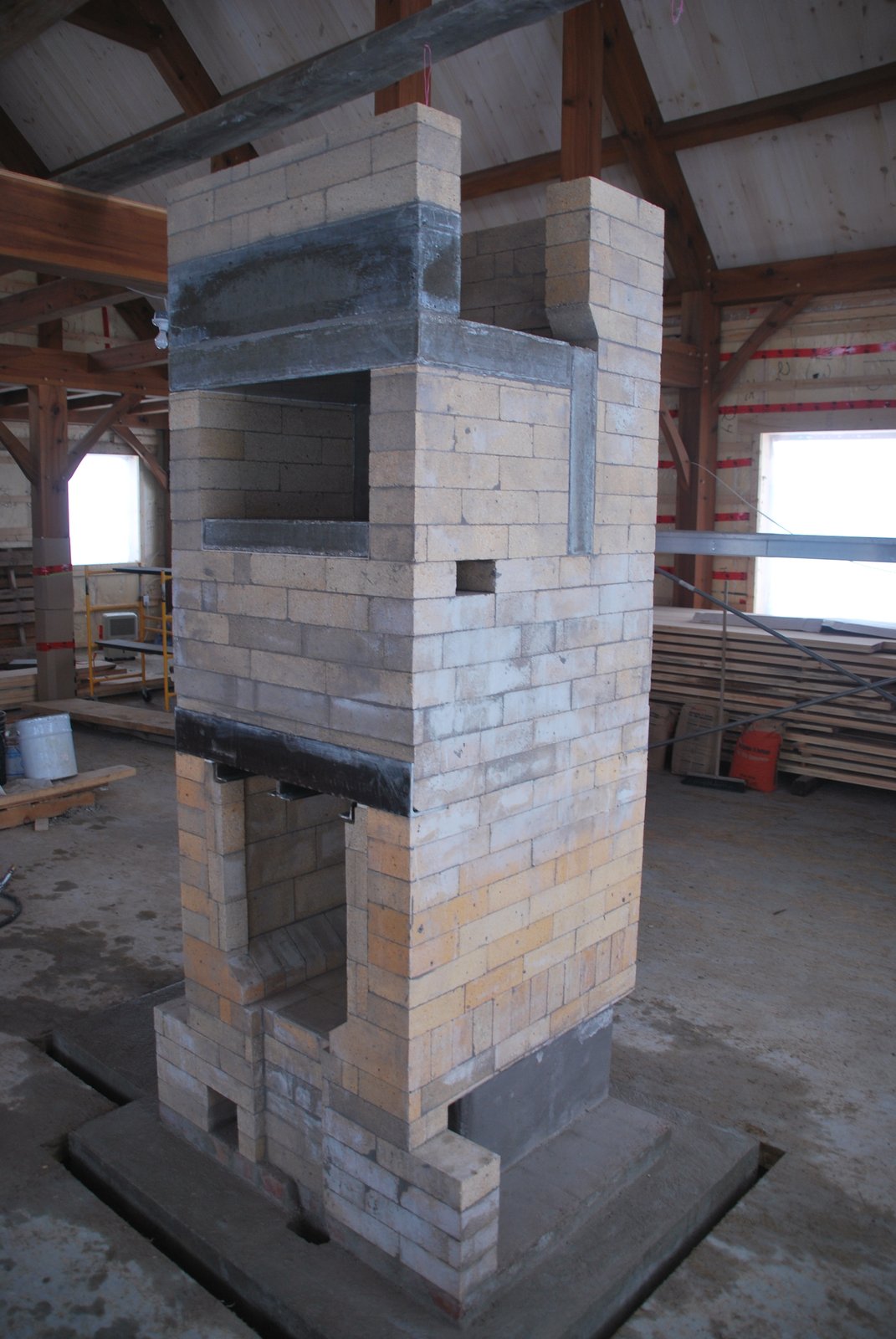
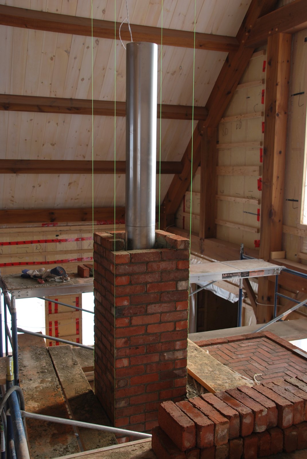
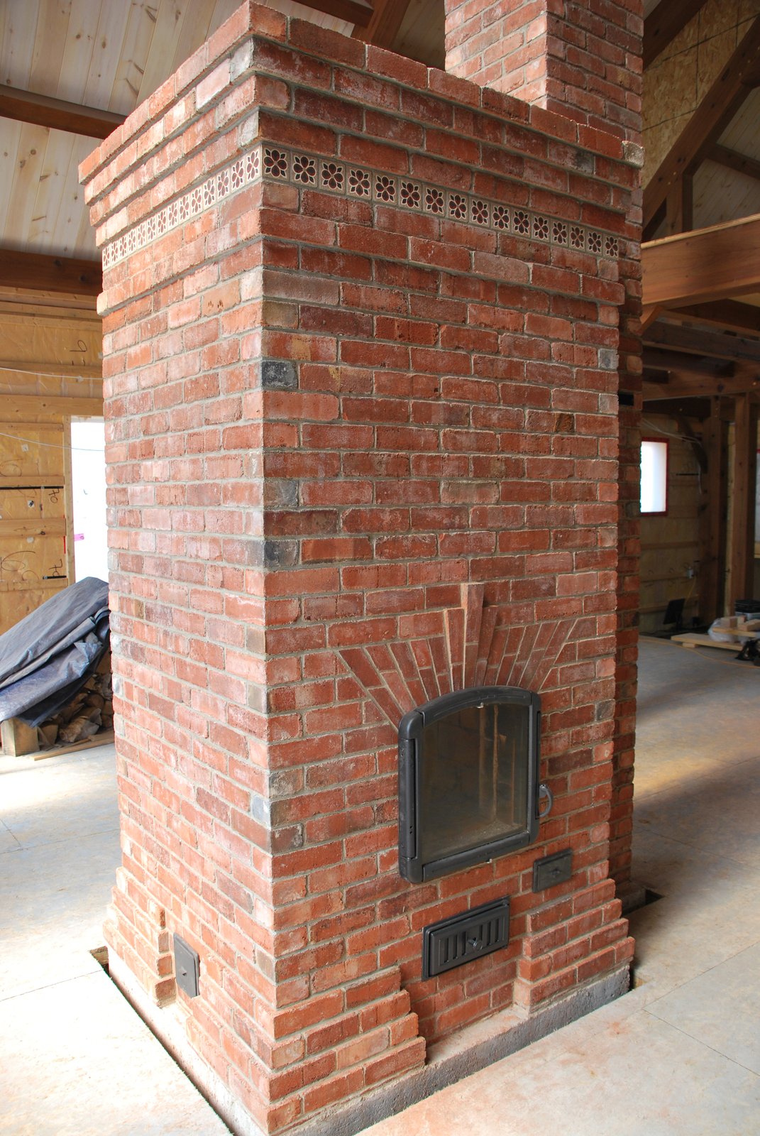
The stove will be built in a space with a 20 foot cathedral ceiling. Having the brick work of the chimney visible to the ceiling was a requirement.
The first 8 feet of the 21 x 21 inch brick chimney will contain an 8 inch round clay flue liner. This allows the installation of a manually operated guillotine damper at 6 feet, and the inertia of 8 feet of solid masonry chimney.
8 inch ID stainless steel flue will be used after 8 feet, in order to avoid using clay liner tiles which can deteriorate on the upper portion of the chimney. The clay flue tiles used in the lower 8 feet are gasketed and backfilled against the brick, making it unlikely that they should move or leak if becoming fissured. As the tiles below the damper remain relatively warm, they are less susceptible to thermal shock. It could also be argued that the first 8 feet of masonry is part of the stove, being an updraft channel, and the chimney proper, starts after the anchor plate at 8 feet.
Insulated prefabricated 8inch ID chimney could not be used after the first 8 feet as it would be too large for a 21 x 21 inch brick wrap without cutting the backs off 4 brick per course. This would effect the stability of a 29 foot chimney which should be built in full modules.
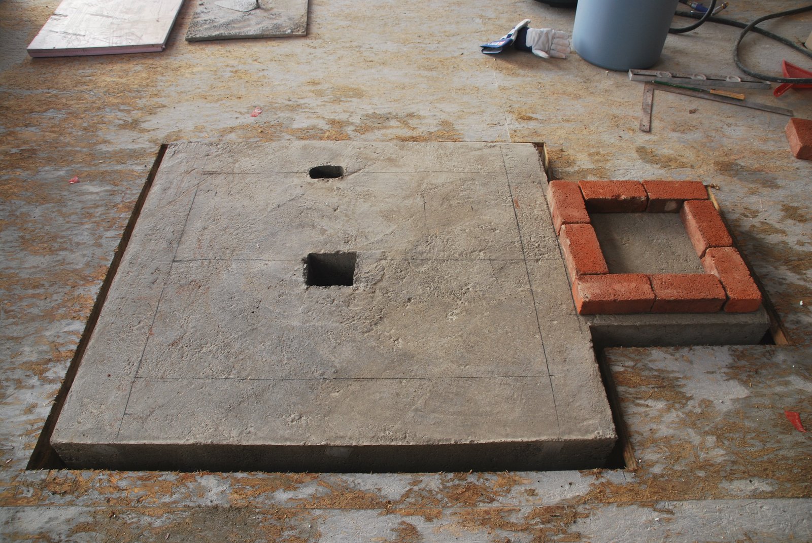
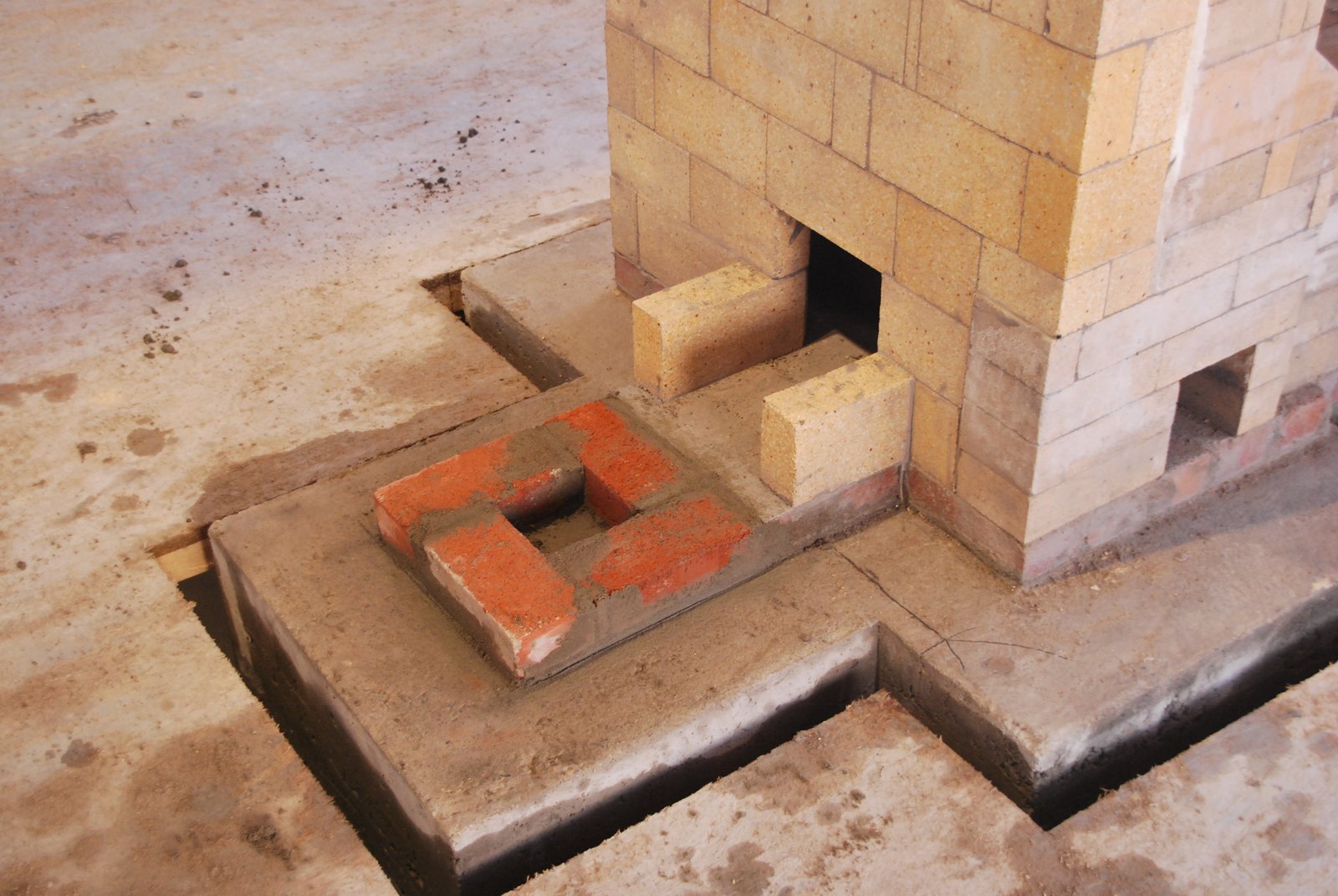
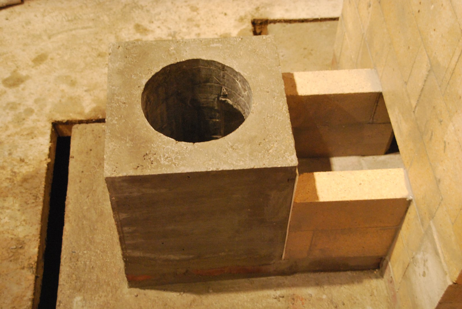
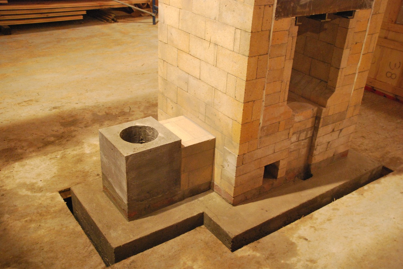
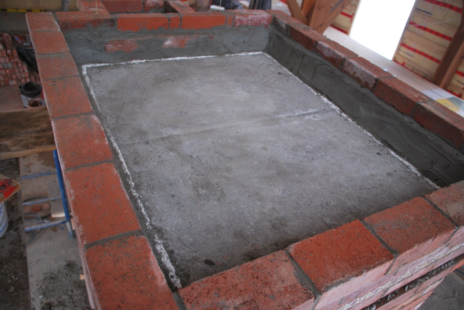
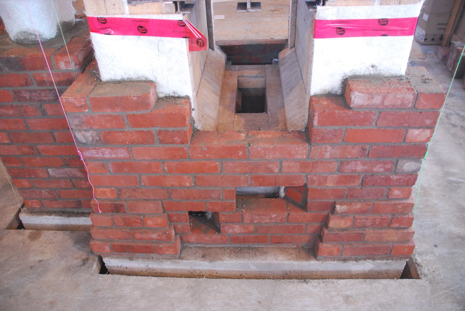
The elevated foundation. The opening in the centre is for the ash drop and the smaller opening behind it, an outside air intake. This smaller opening is positioned to be between the core and facing just below the air intake door in the facing. It leads to the void of a block on the last course below the slab. The stove will not use outside primary air. This set up though allows outside air to be linked up in the future, should it be desired, by opening the block on the last course of the foundation in the basement.
The slab is 1.75 inches higher than the surrounding floor, and there are no cantilevered noncombustible floor extensions of the slab in front of the fire box openings as there will be 2 inches of concrete poured onto the floor once the stove has been built.
The first 4 courses of the core in clay brick layed in Type N and the rear manifold wall in medium duty refractory brick. The rear manifold wall supports the core and refractory brick are wider than the clay facing brick, so more stable when employed in this situation. The chase in the centre of the rear manifold wall allows primary air to pass between the core and facing. The square opening is an access opening to the left side channel via the rear manifold.
The diagonal chase in the last course of clay brick forms a supplementary under air channel.
The first course of medium duty refractory brick bridges the rear manifold. Note the over hang on the brick that bridges the supplementary underair channel opening into the ash drop channel. This helps avoid embers entering the channel as they drop through the grate into the foundation.
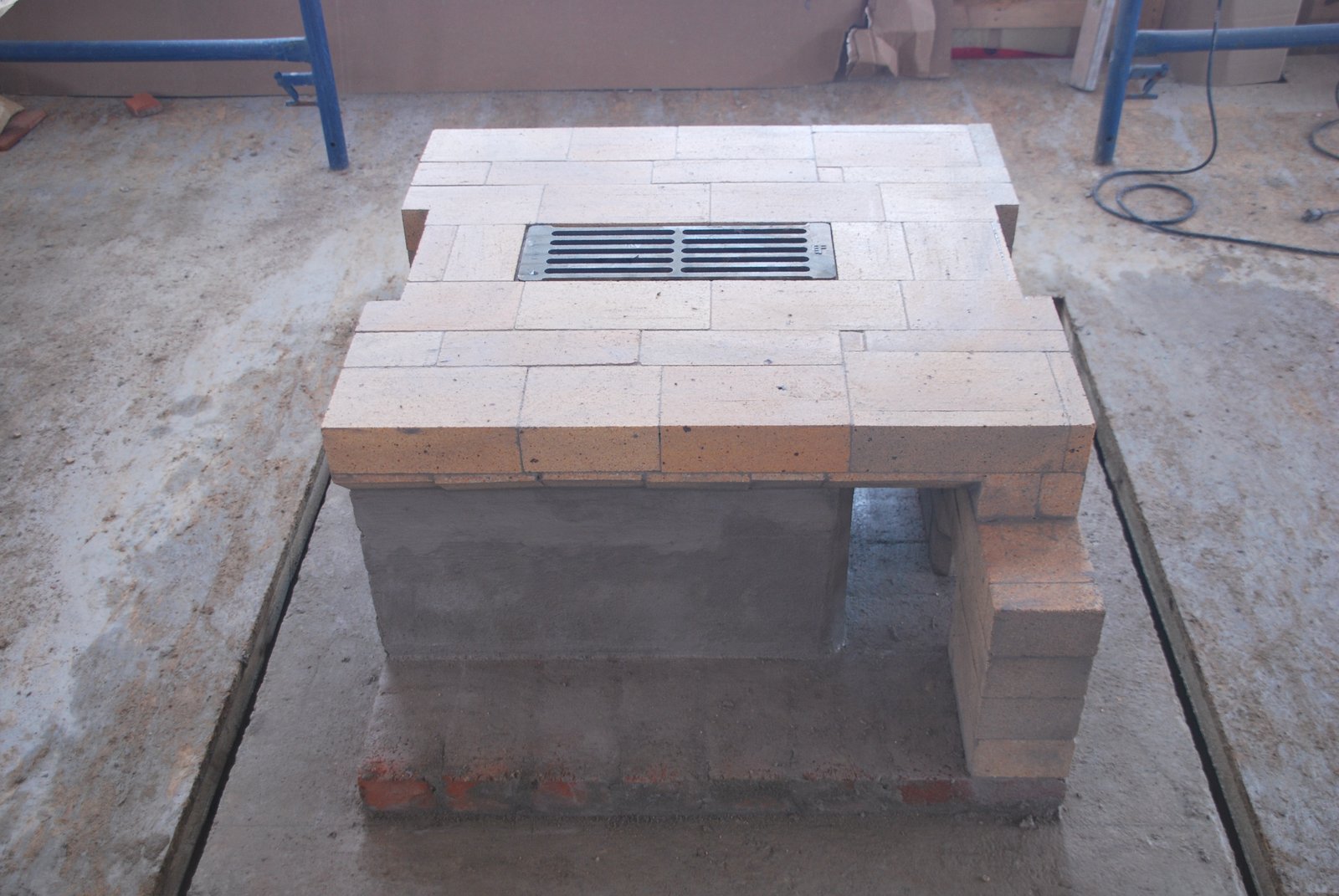
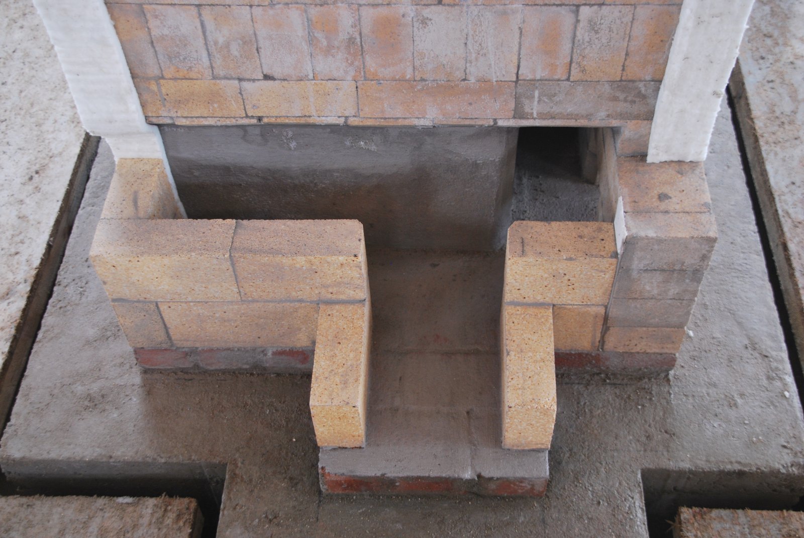
The second course of refractory brick are high duty, forming the fire box floor with the cut out for the support lugs of the grate.
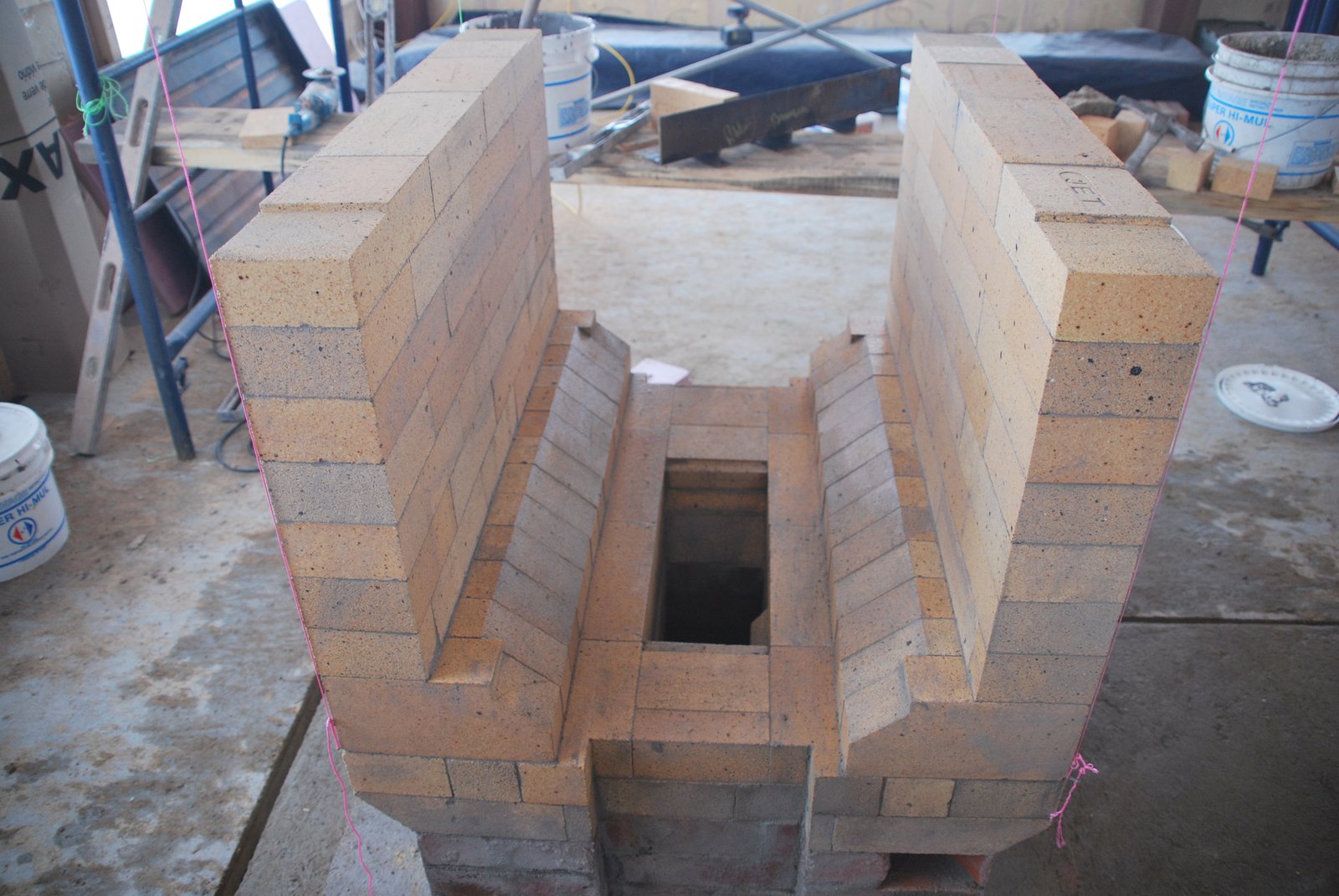
As the stove will have a fire box loading door on 2 opposite faces, there is a primary air chase at each end of the hearth. This allows primary air to enter from beneath both fire box doors. The fire can be balanced and kept central by adjusting the flow of these intake channels with the air intake doors. Stoves with 2 fire box doors are referred to in the trade as "see through's".
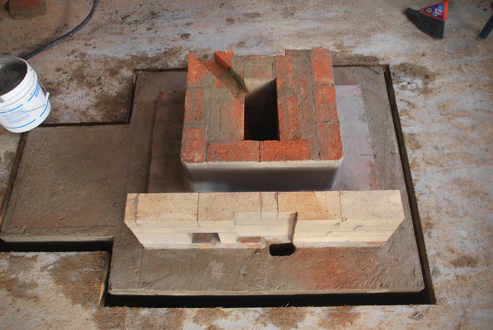
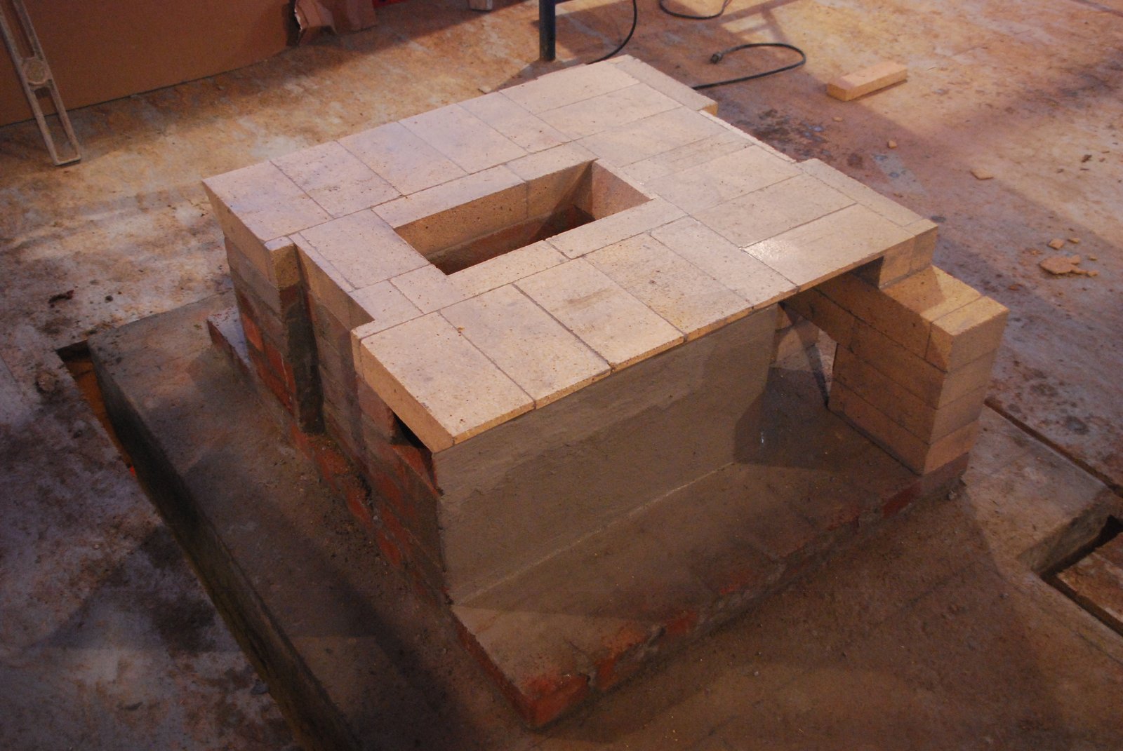
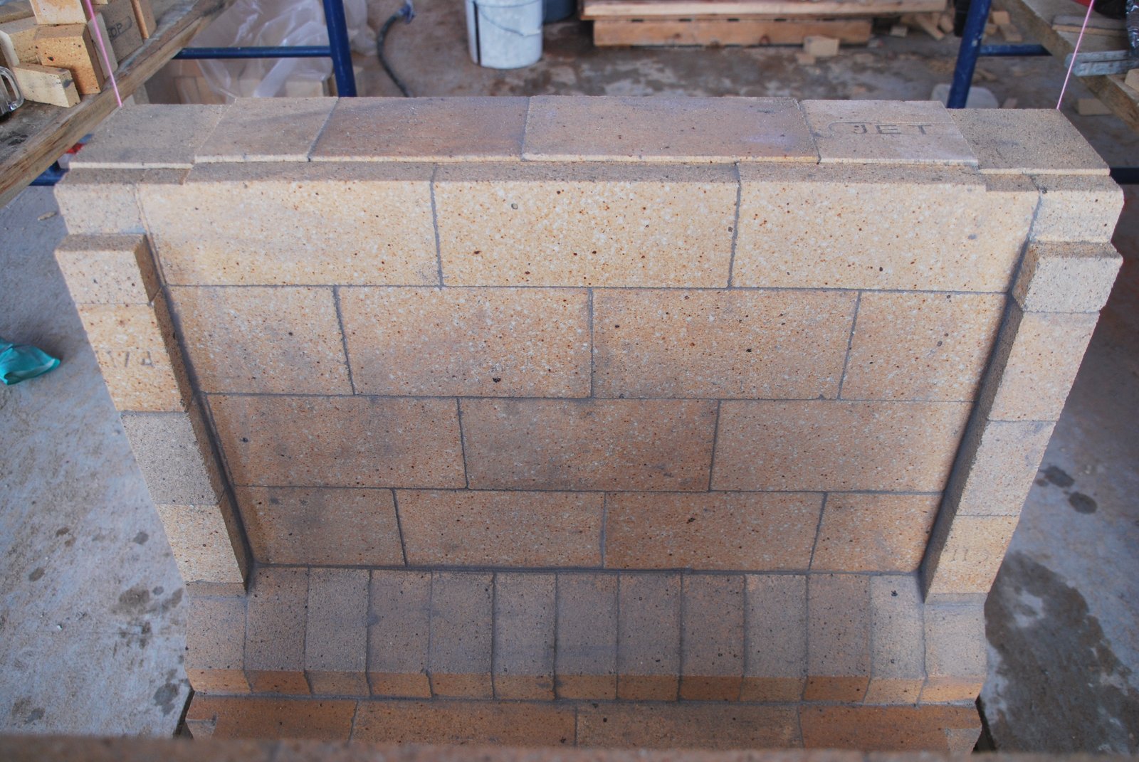
The first course of the fire box walls. Note the 4 heels on which the liner will turn and shield the protruding door jambs of the fire box opening in the facing.
The fire box walls and cut outs for the two lintels. The fire box walls, floor, and several courses above the lintel are in high duty brick.
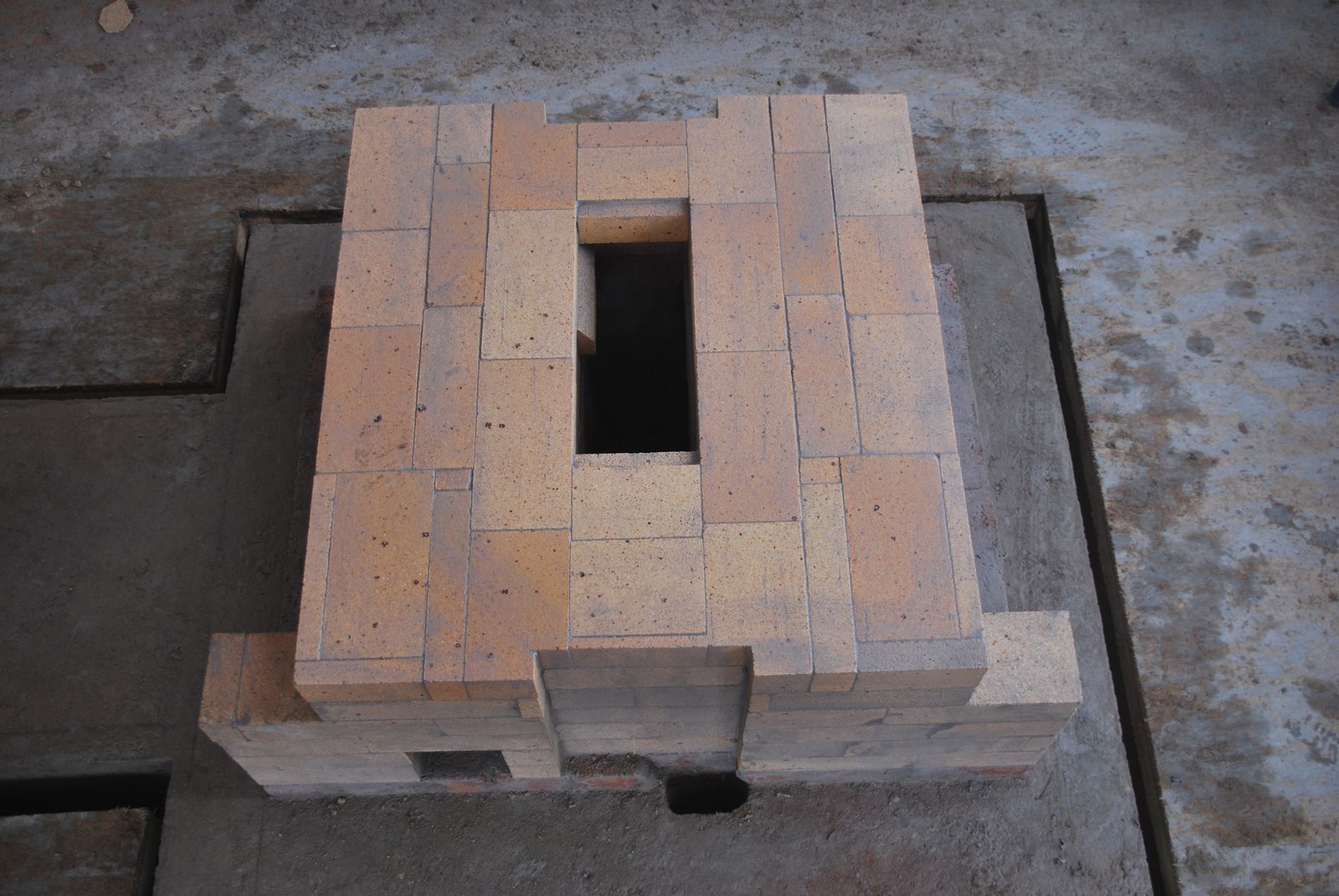
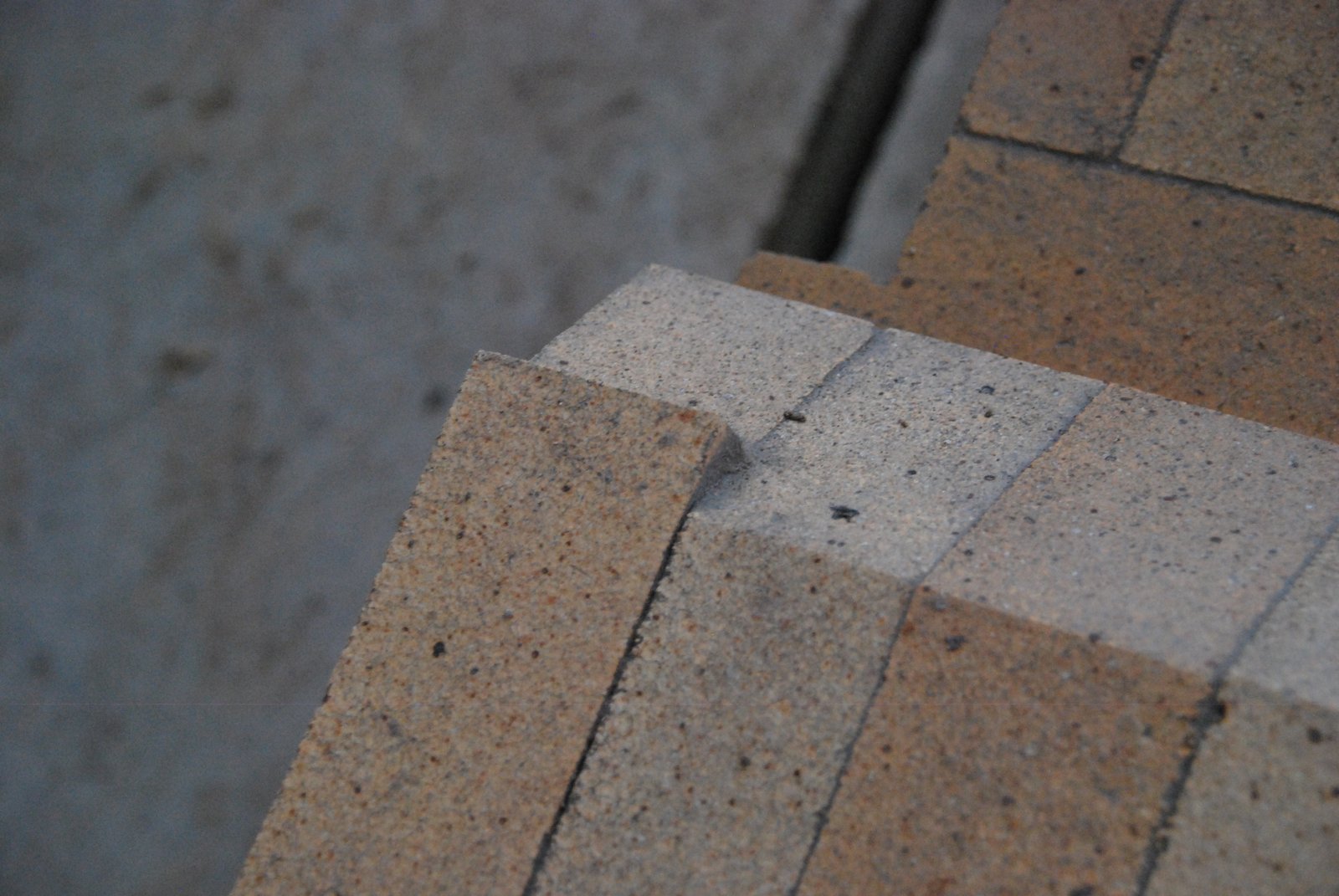
The fire box liner is layed in splits.
The liner is cut on eighth of an inch lower then the walls to accommodate a ceramic paper gasket.
Quarter inch deep cuts into the upper surface of each end of each wall will accommodate the quarter inch thick angle bar lintel.
The upper surfaces of the liner are gasketed with ceramic paper. This gasket prevents the liner lifting the courses above it, as it becomes hot and expands vertically before the walls behind it do. The risk of doing this is that the liner may wander or peal if a large fire is lit from cold. Alternatively the liner could be trapped by the courses above, and have no expansion joint.
The surface of the recess cut to accommodate the lintel, is gasketed with a single leaf of aluminium foil. Before laying the foil an extremely thin layer of loose HTC is spread on to the surface of the brick, the foil layed, and then the lintel immediately put in place and moved rapidly from side to side. The function of the HTC beneath the foil gasket is to distribute evenly the weight of the core above the lintel, over the face of the brick. With a dry cut recess the lintel would inevitably rest only on certain points on the cut surface, creating pressure points in what is an important brick. The foil also provides a slip joint allowing the lintel to slide over the brick, and a bond brake to prevent the HTC on the brick below sticking to the lower surface of the lintel.
There is considerable lateral expansion on the lintels, and as the fire box walls of a see through have no corners, it is important that the lintels don’t drag out the walls as they expand.
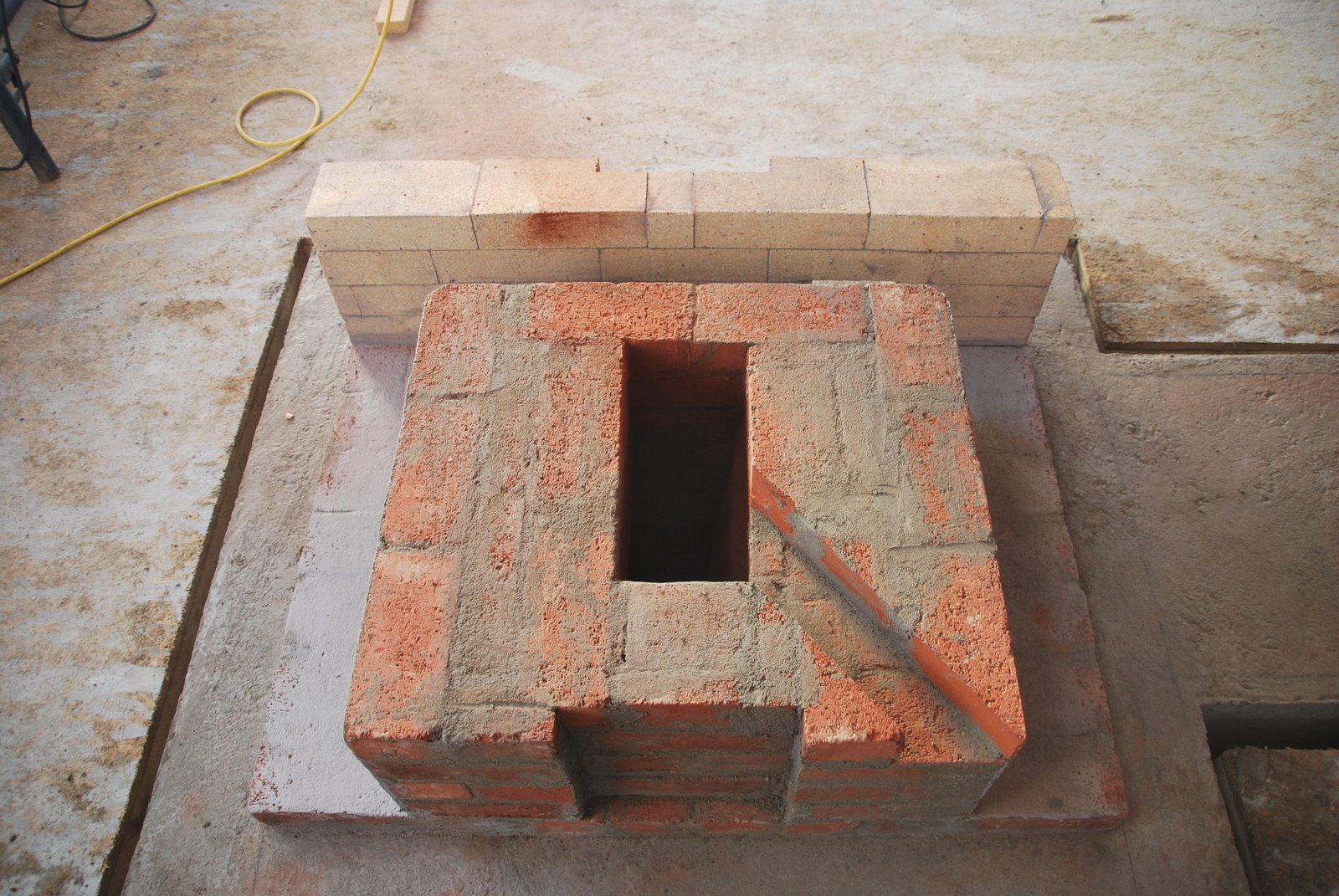
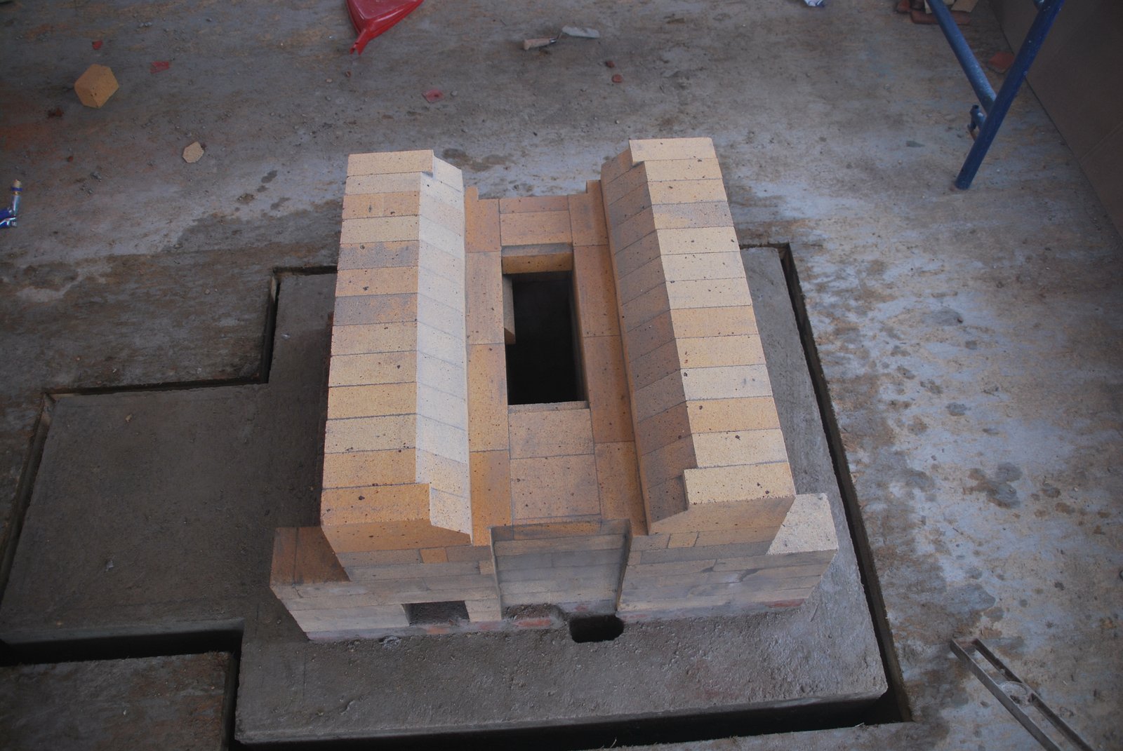
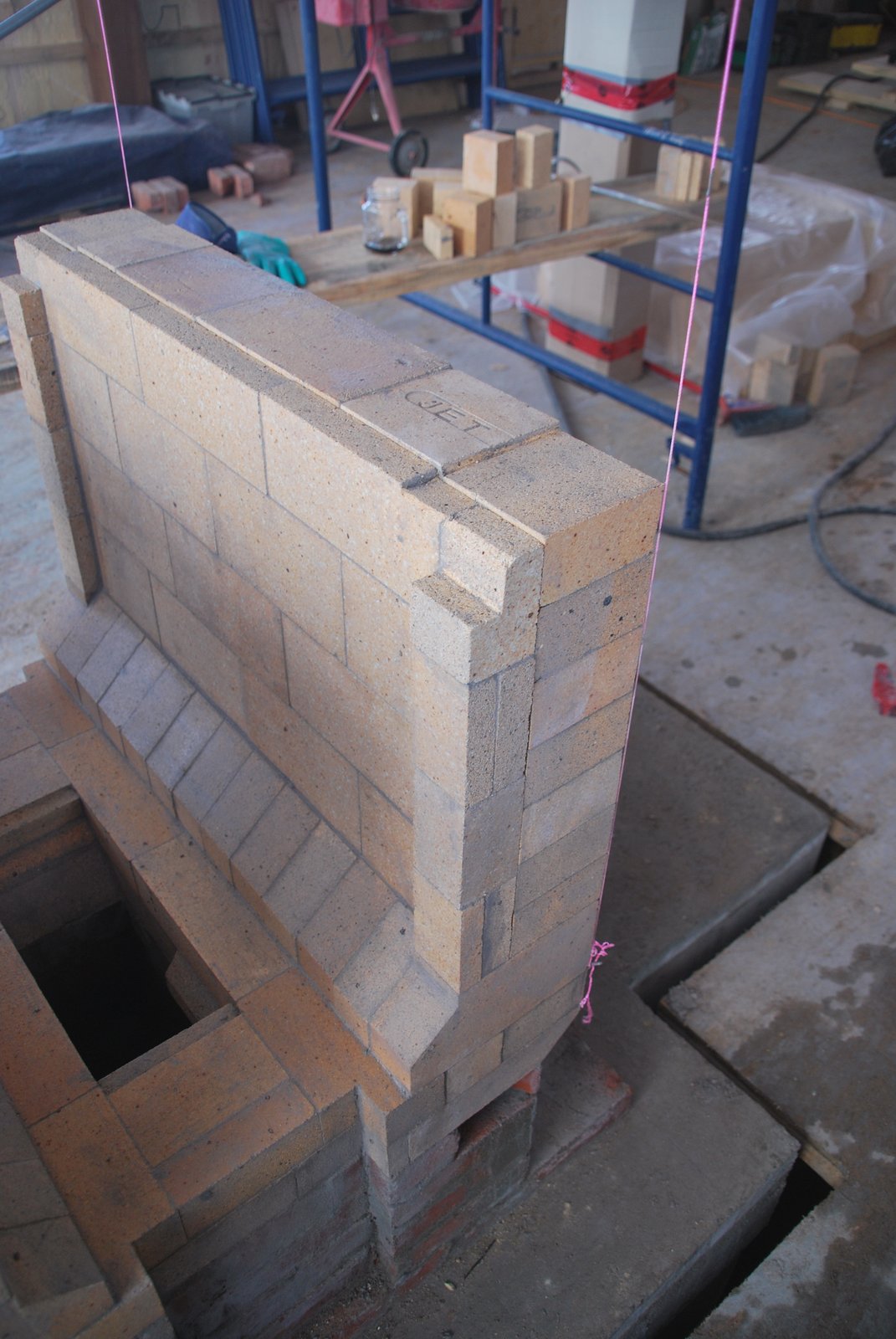
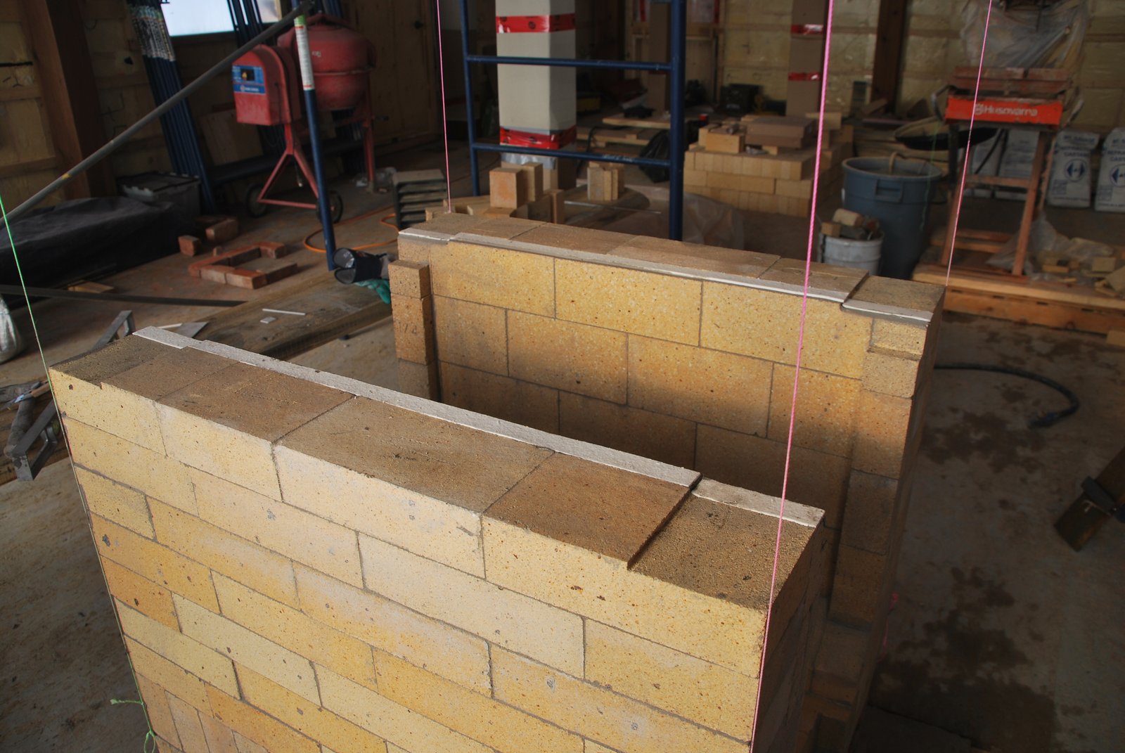
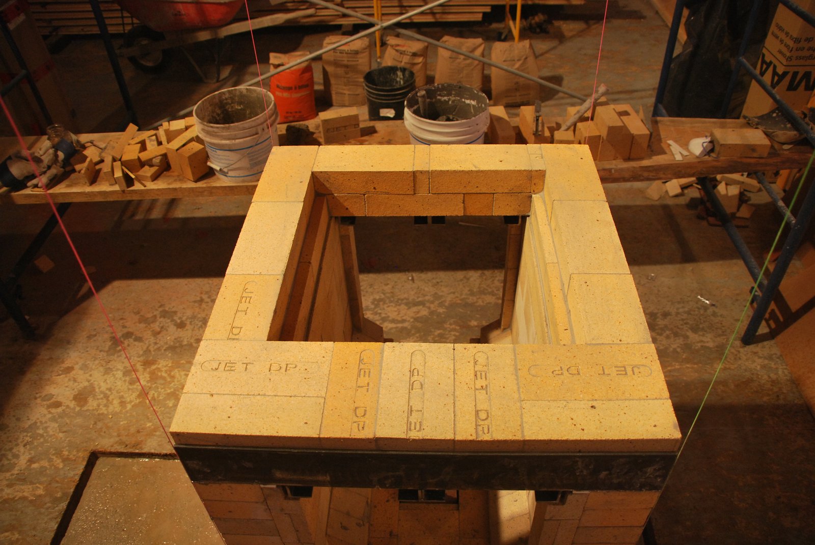
The second course over the lintel. Note that the first course is layed out of line and backed up with cut pieces. This permits the brick of the first course to trap the gasketed liner.
The completed second course. Symmetry is of little importance when corbeling above the fire box.
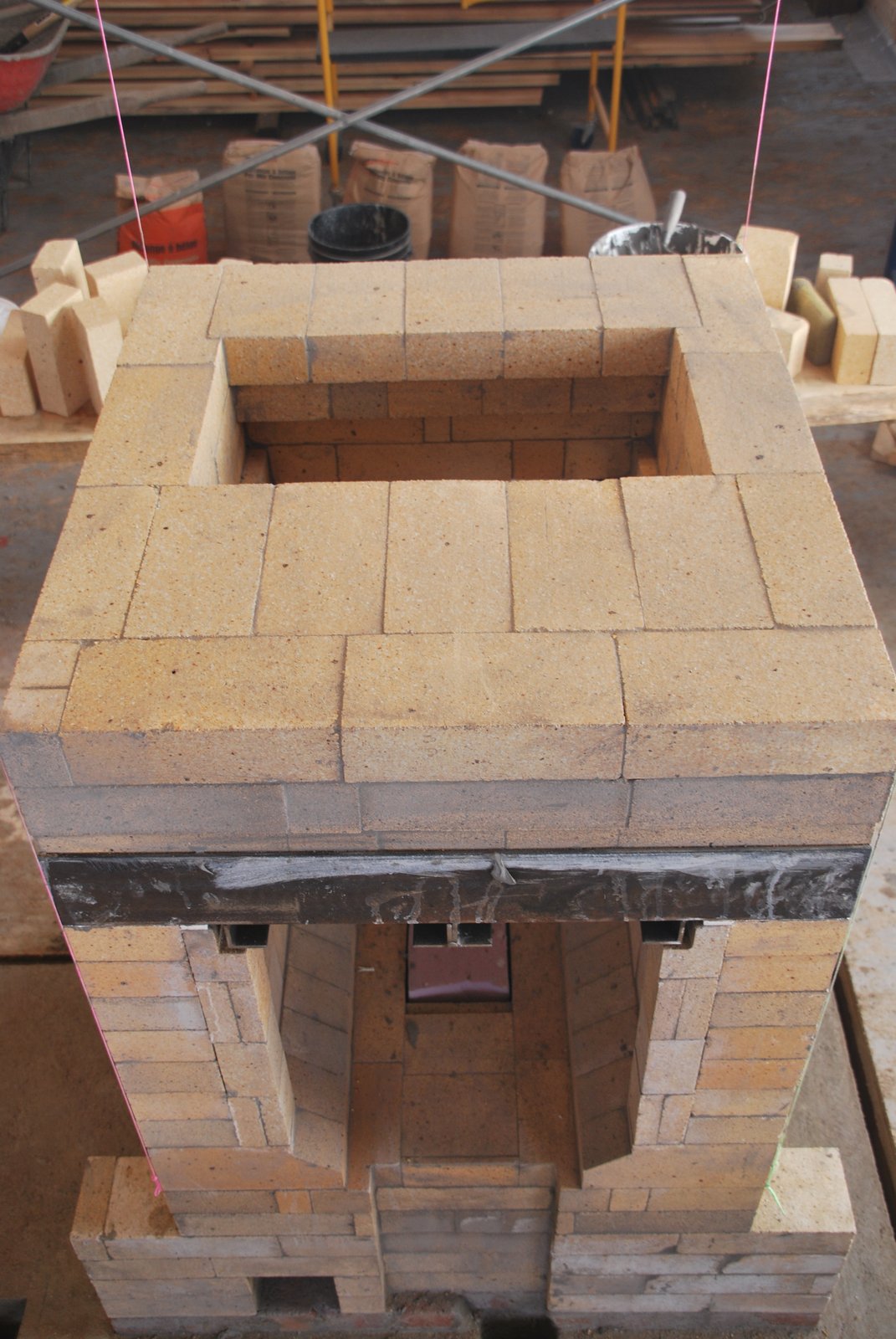
The fourth course above the lintels. Each corner brick on the opposite side, has been notched in order to accept the brick of the corbel that is layed against it. The notch allows some of the length of the brick in the corbel to rest upon the fire box wall, and reduces the number of head joints in the side walls running between each corbel. Stack joints in these side walls should be avoided when possible.
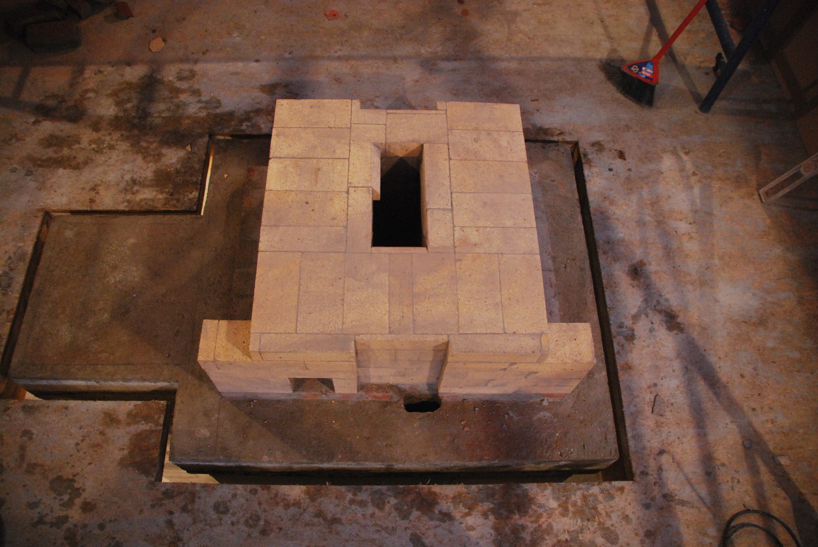
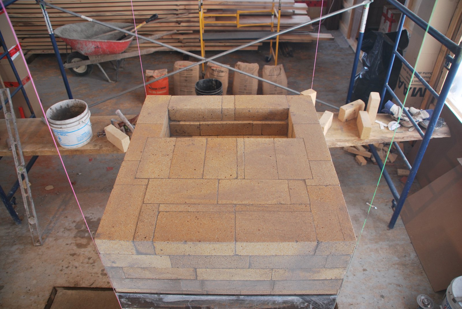
The sixth and final course above the lintels. Note that 4 bricks in the side wall have been notched, for reasons outlined in the previous paragraph.
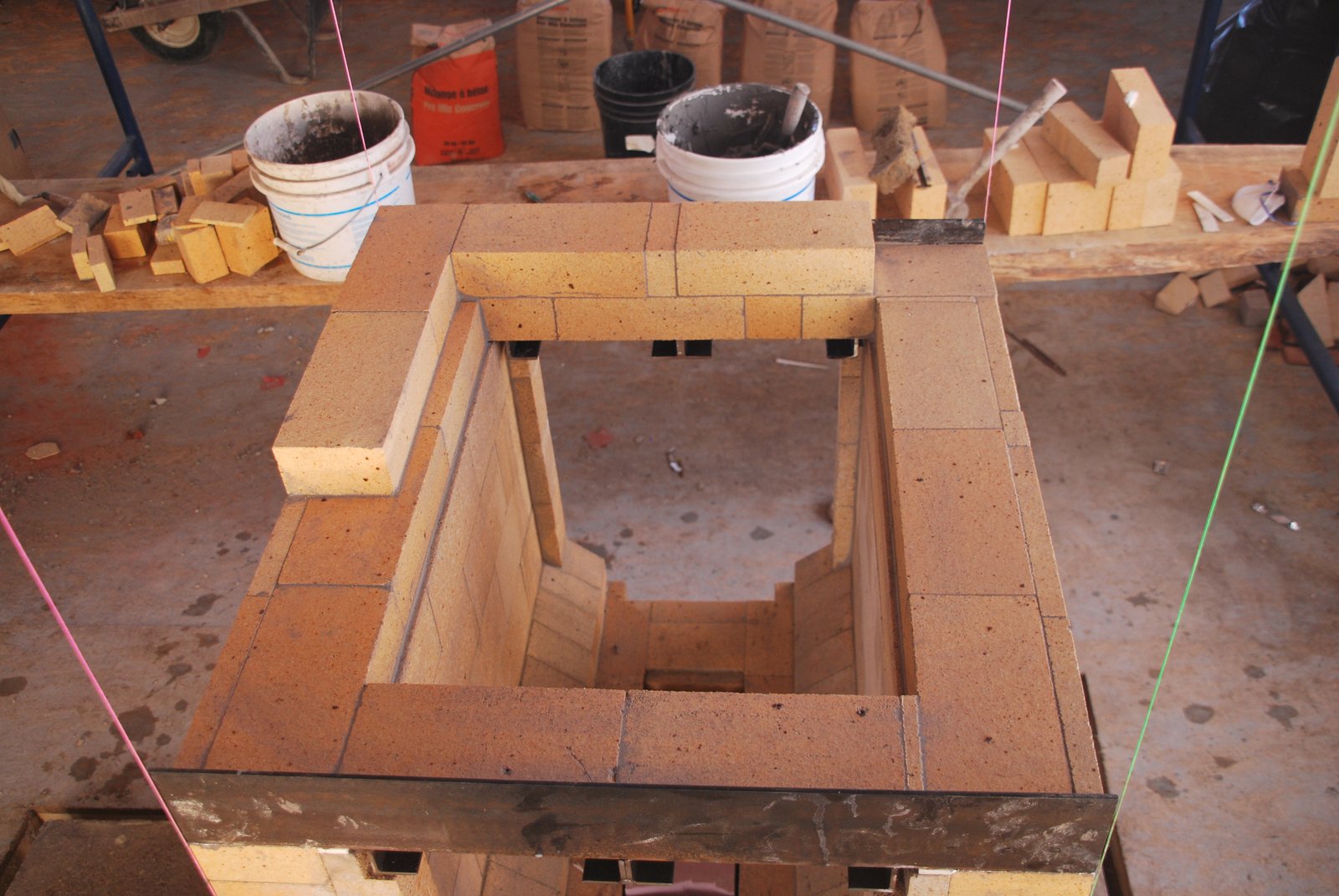
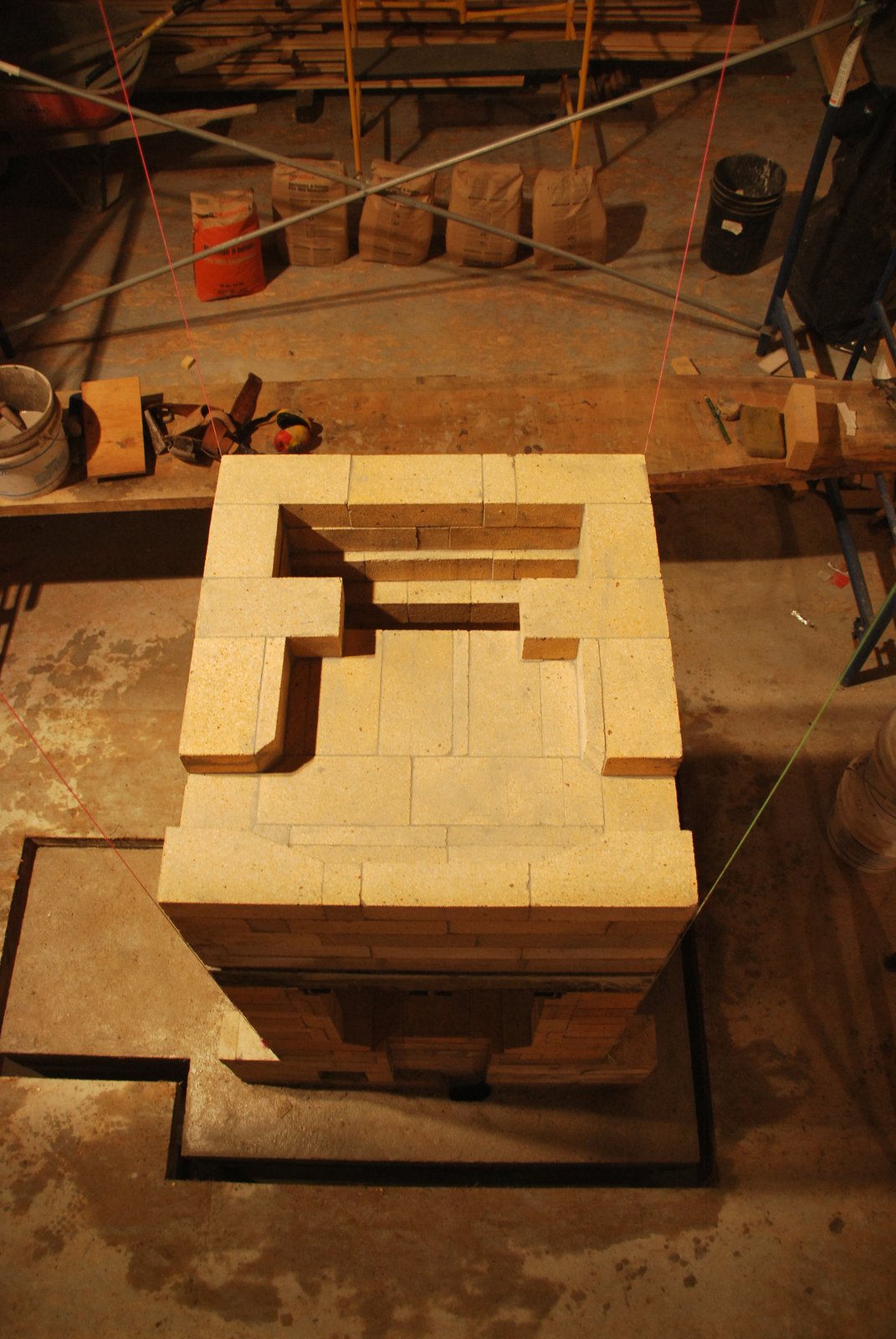
The seventh course above the lintel forms the under hearth channel of the oven.
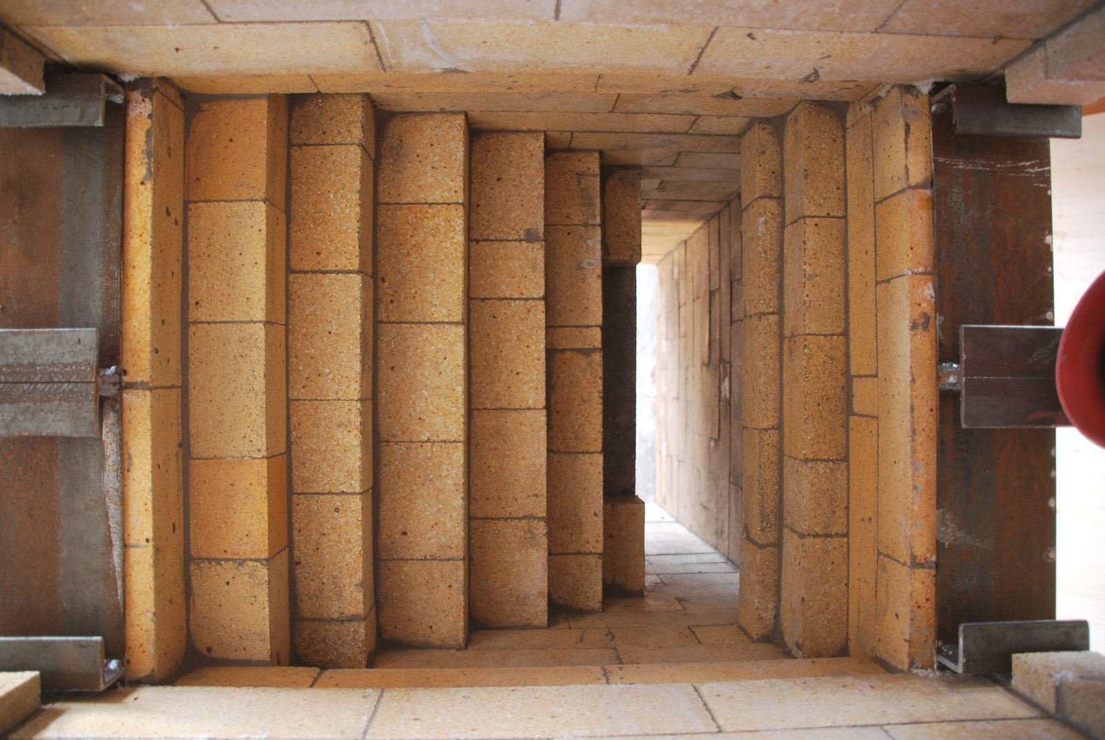
View up through the fire box's corbeled ceiling.
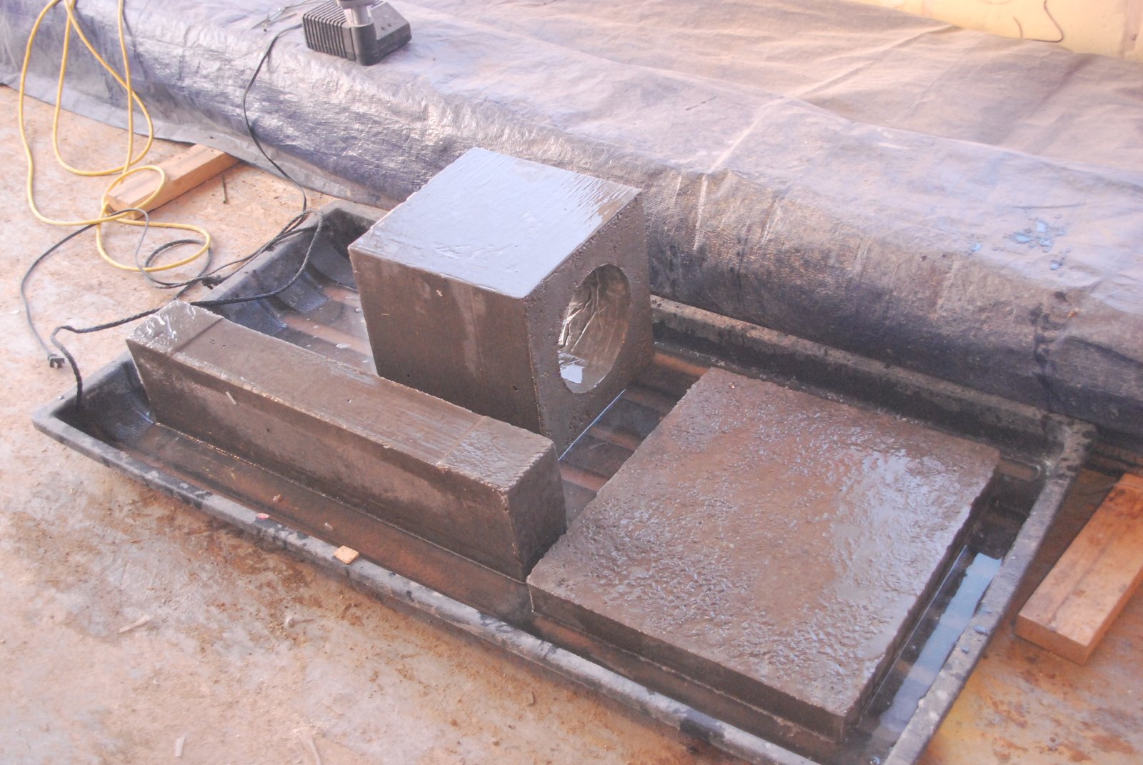
Some of the castable modules to be used: The oven load relieving lintel, hearth slab, and chimney connector.
A paper gasket is stuck into position with HTC onto the surfaces that will be contacted by the hearth slab .
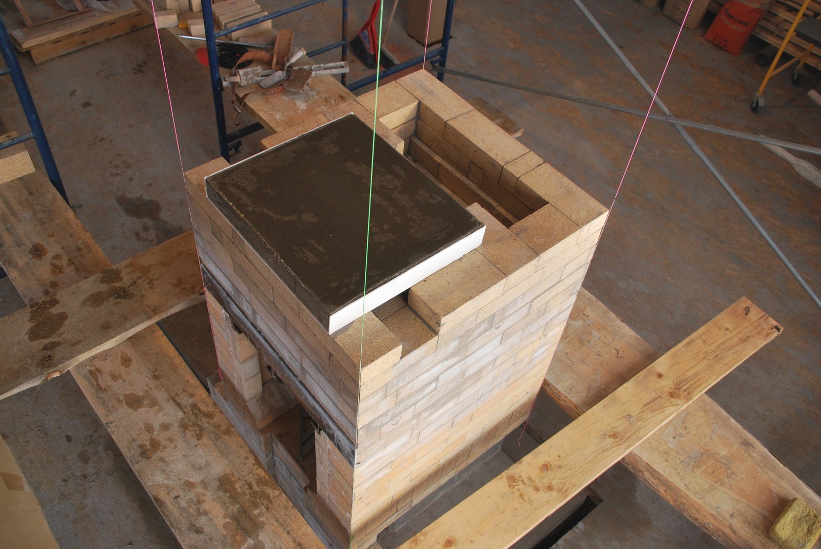
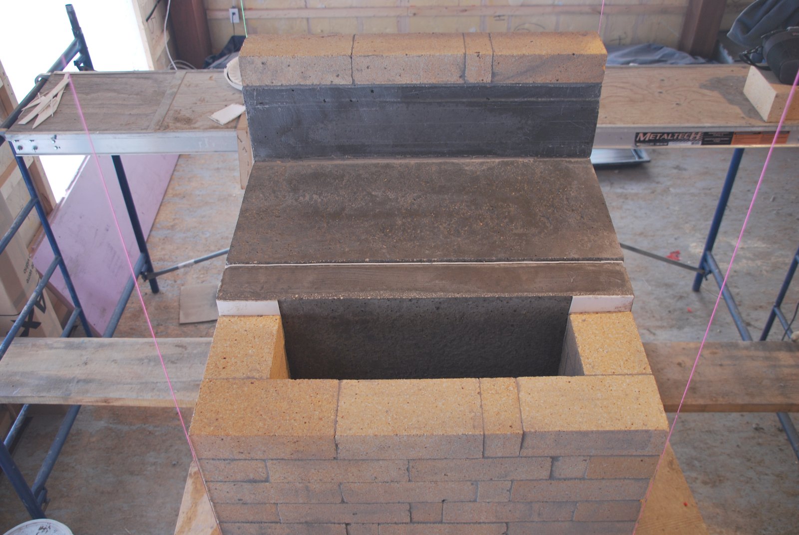
The hearth slab in position. The paper gasket along its side prevents contact with the side walls of the oven.
The hearth slab is completely free floating, having no solid contact with the masonry around it.
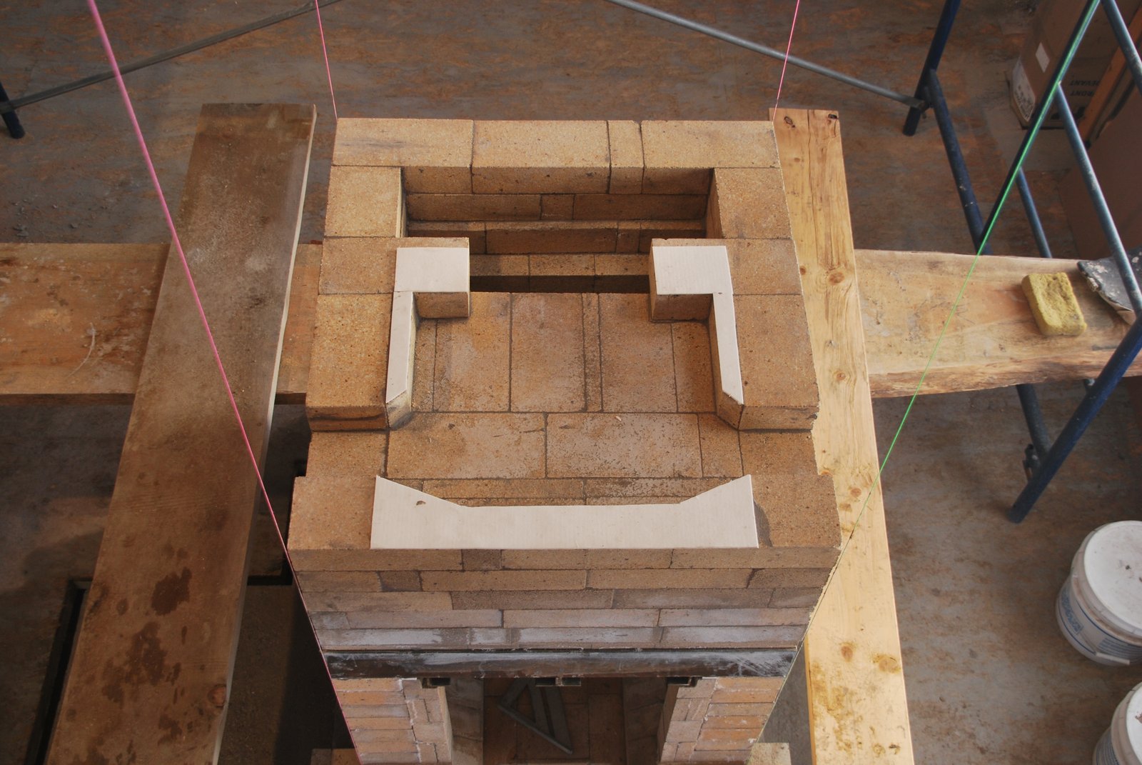
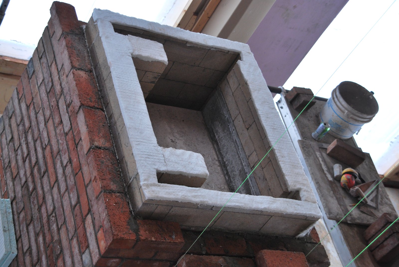
View of the ovens bake chamber from above. The back slab is also free floating.
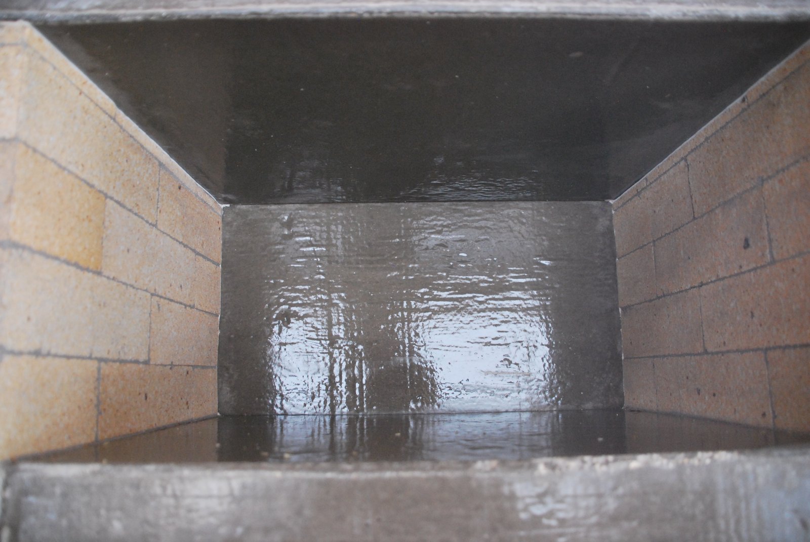
View inside the bake chamber.
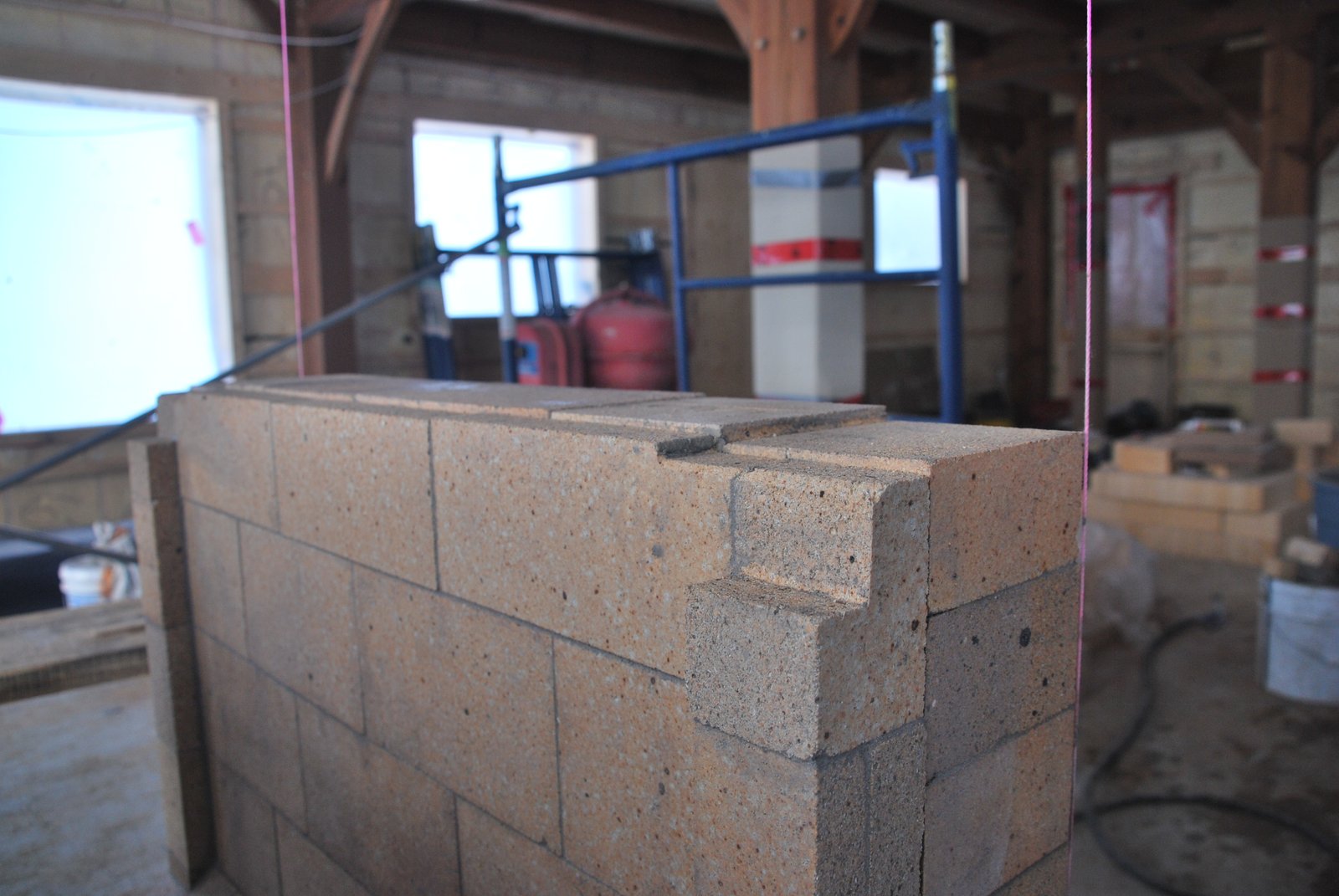
In order to tie it in to the side channel wall the first course of the chimney connection must be layed at the same time as the side channel wall.
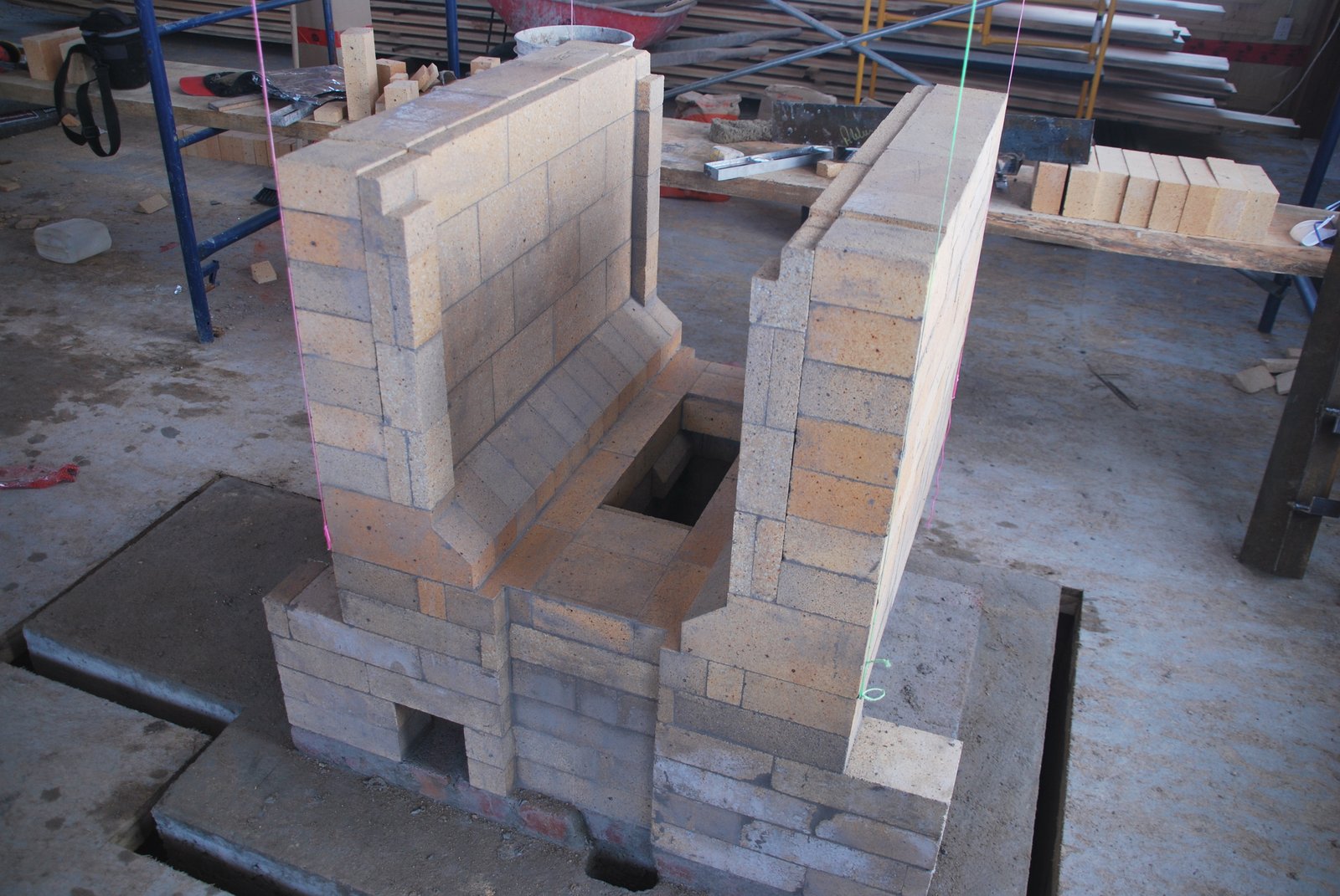
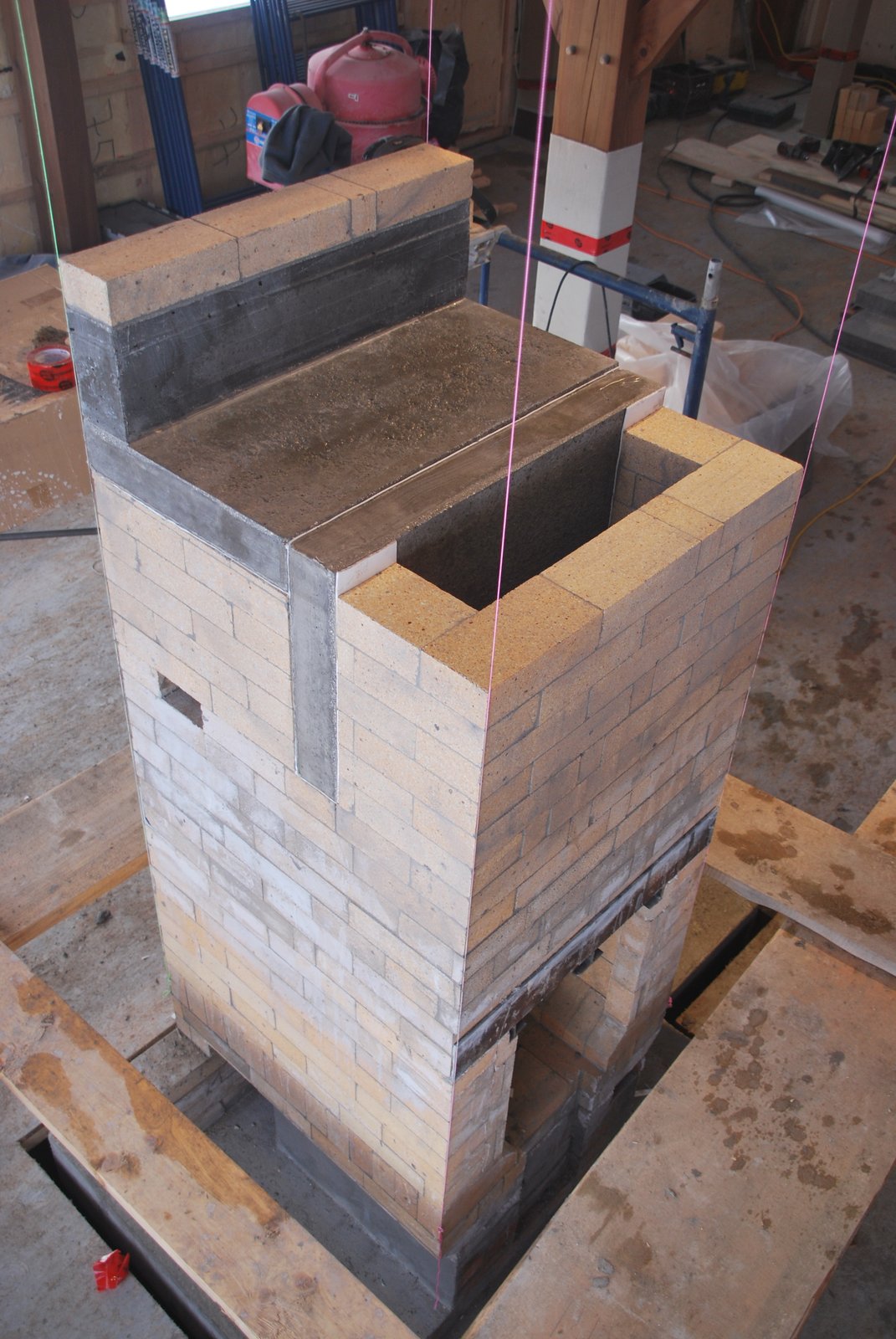
The completed core less capping slabs. Note the first course of the chimney connection protruding from the left side manifold.
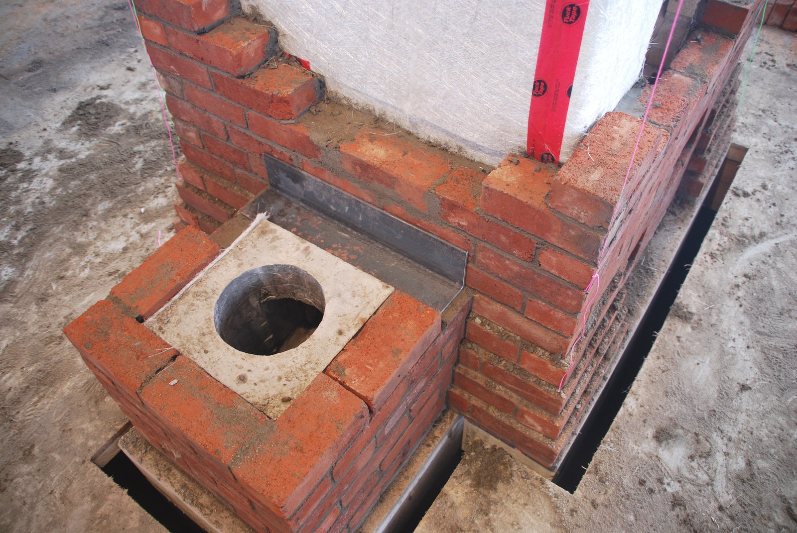
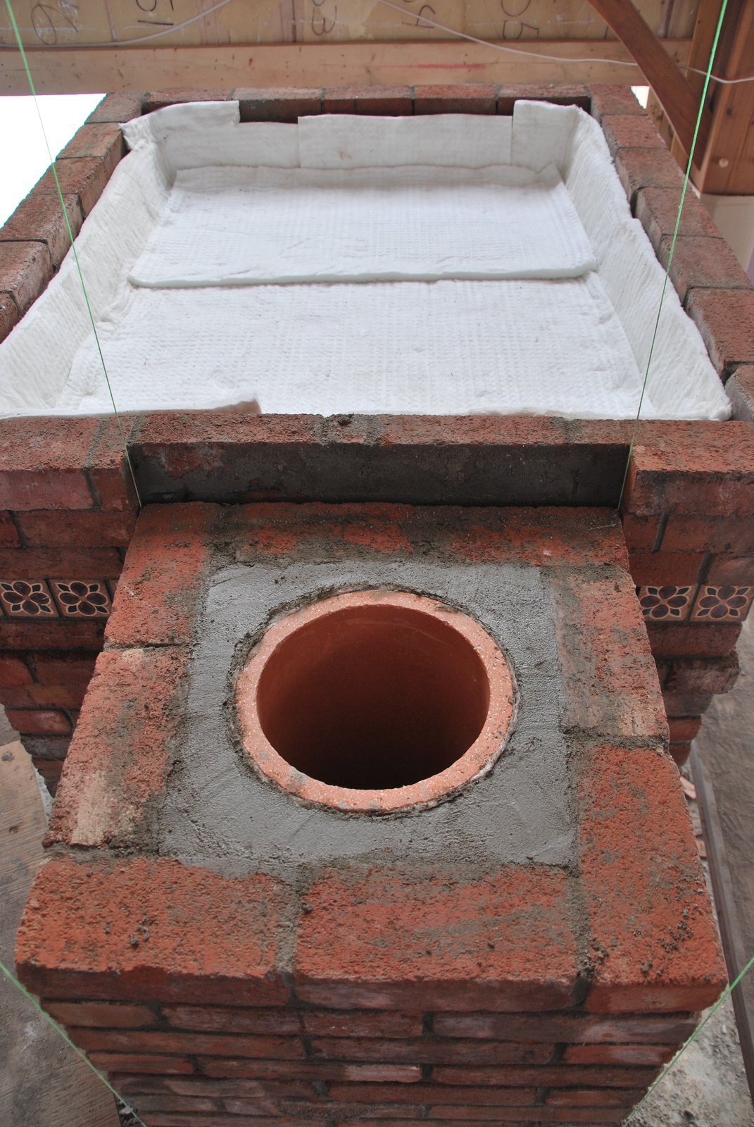
The connector will be layed onto a course of clay brick. The recess in the centre will accept any water that condenses in, and drips down, the flue, and so prevent it from running through the connection into the manifolds.
The castable refractory concrete connector is layed in type N mortar and is gasketed against the connection walls.
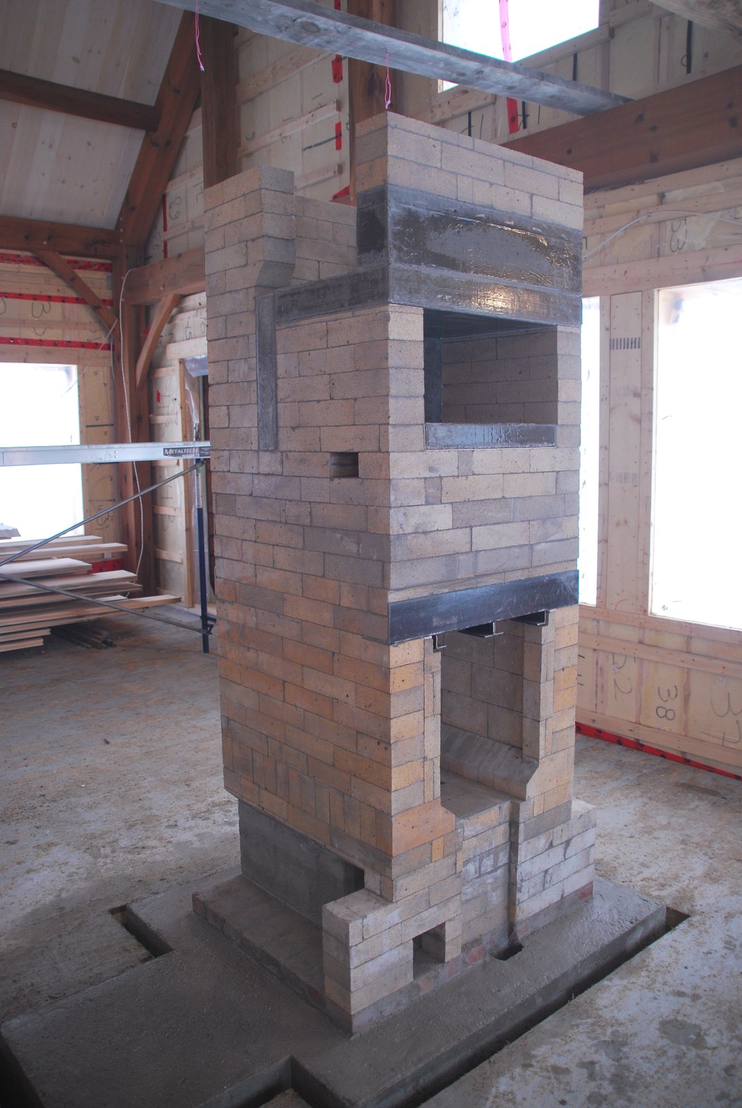
The completed connection.
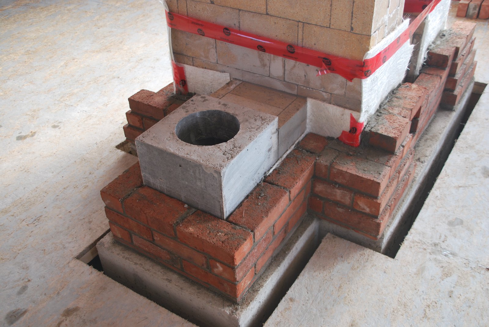
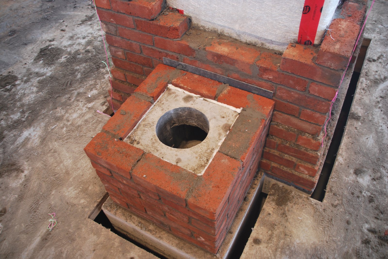
The start of the facing around the base of the stove and the chimney connection. The connector is gasketed with 2 sheets of fibreglass mat. (Though there looks to be no gasket around the connector in this image.) The fibreglass mat is temporarily held in place with cellulose construction tape.
The connector was cast three sixteenths of an inch smaller in all directions, than the inside dimensions of the brick facing of the chimney, in order to allow it to be gasketed. Apart from the bed joint of the connector being layed in mortar, the whole flue of the chimney will be free floating, and have no physical hard contact with the facing brick.
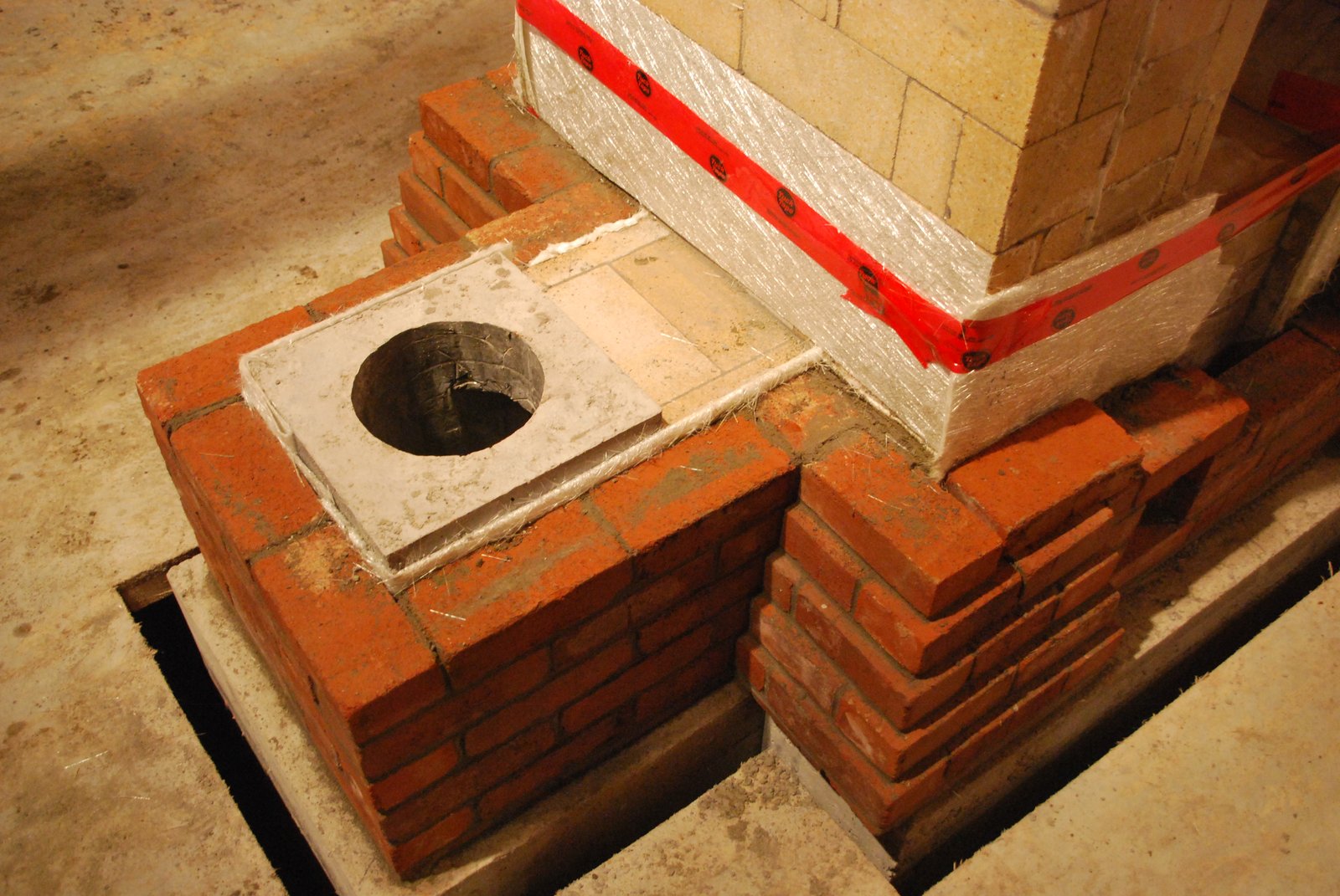
Note that the core is gasketed with one sheet of fibreglass mat on the sides and 4 sheets on both front and back.
The connection is bridged using a quarter inch thick piece of angle bar. Note that the bar is cut shorter than the width of the chimney to avoid seeing the ends of the angle bar in the joint between the chimney and stoves facing. The ends of the angle bar will be gasketed with wool and then the joint filled. The gasket will allow lateral expansion of the angle bar, without it pushing out the joints in the facing at each end.
To reduce the potential for leakage, the first 7 or 8 courses of the chimneys facing are tied into the stoves facing. Above course 7 or 8 the joint between the chimney and the stove is left open. This allows vertical expansion of the hot upper portions of the stoves facing, without it dragging up the cooler walls of the chimney that would not be expanding at the same rate. Also the chimney being only tied in to the facing to course 8 would allow the stove, or chimney to be demolished independently of each other, should that ever become necessary in the future.
This vertical expansion is not a real issue as long as the stove is not over fired. The stove that is never over fired at some point in its life though may be quite rare.
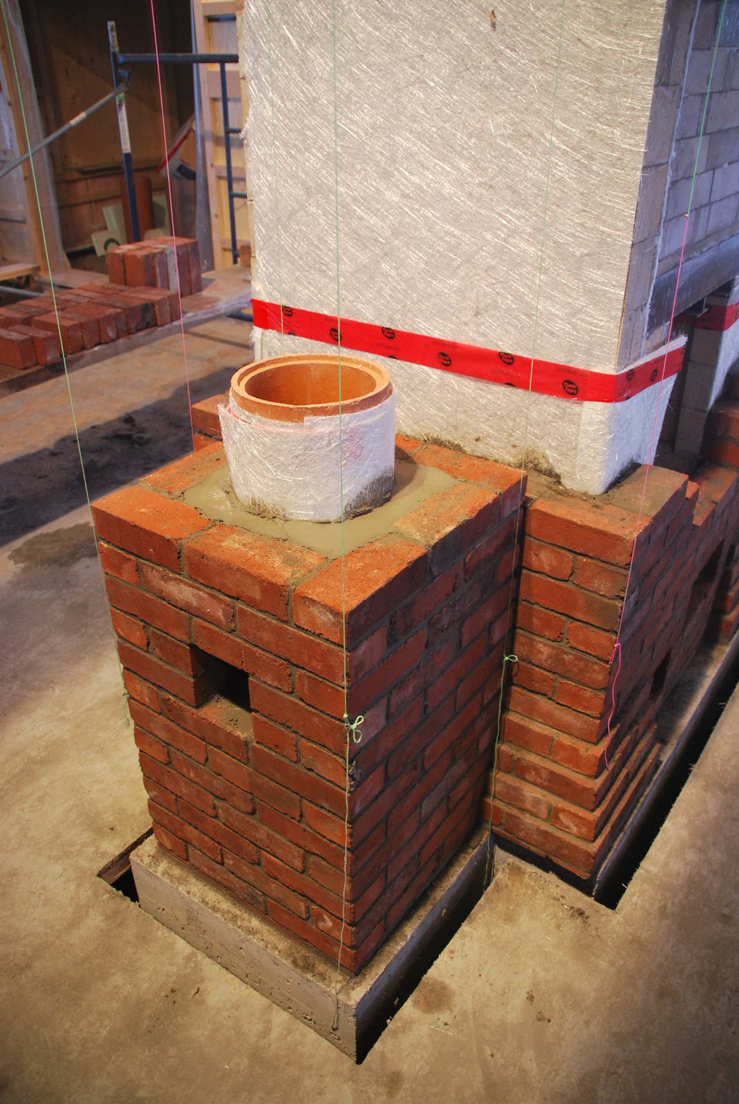
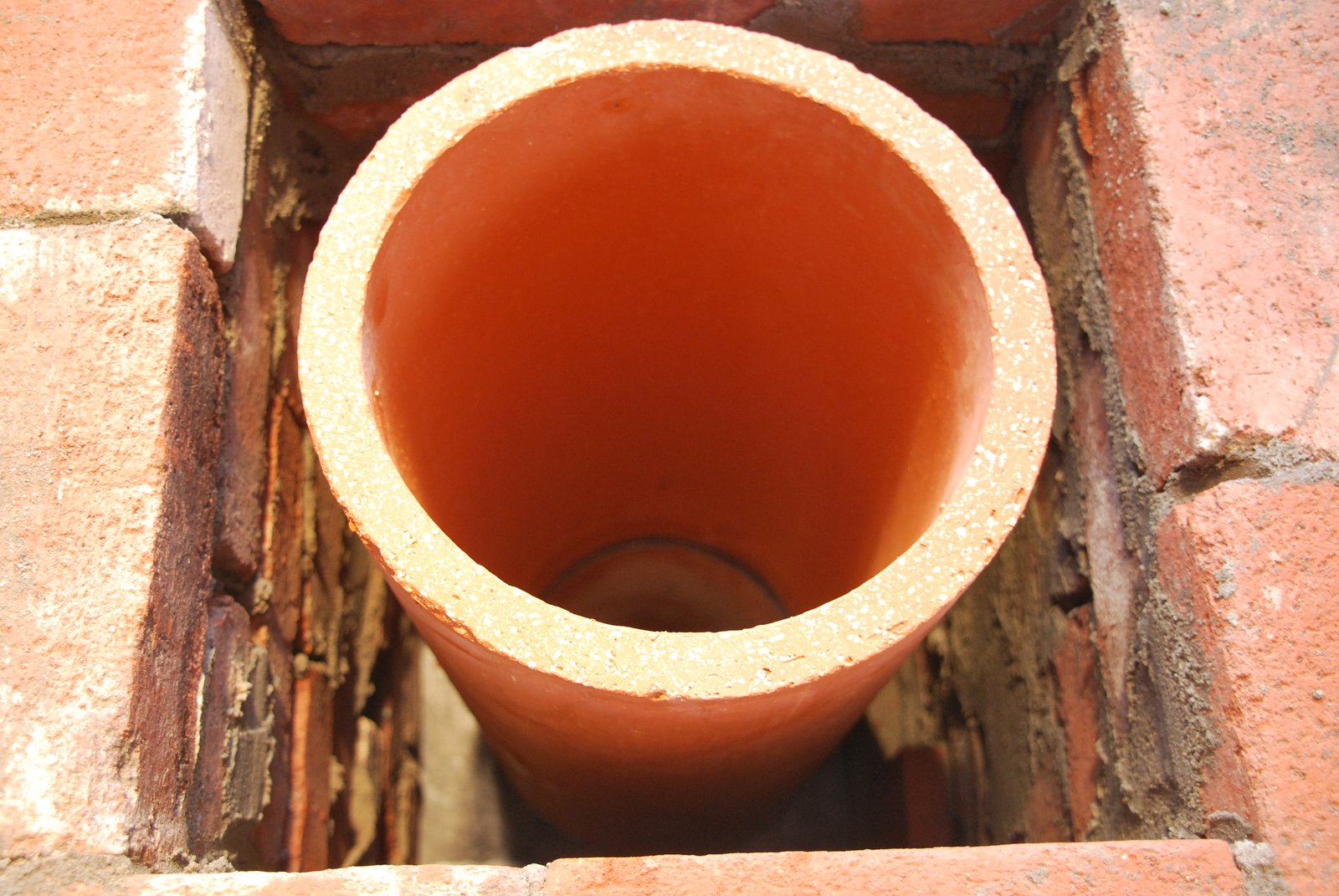
The first 8 inch ID flue liner is layed onto he connection in Type N. The liner is gasketed with 2 sheets of fibreglass mat and the space between the tile and the facing filled with type N mortar. The access opening to the chimney is cut into the first tile, to avoid weakening the connector., by casing or cutting an additional opening into it. Having the opening in the connector would though give easier access to the rear manifold.
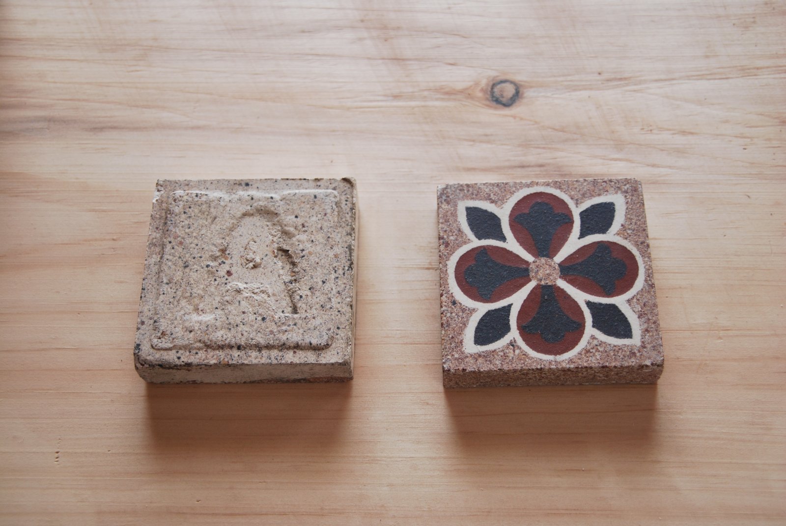
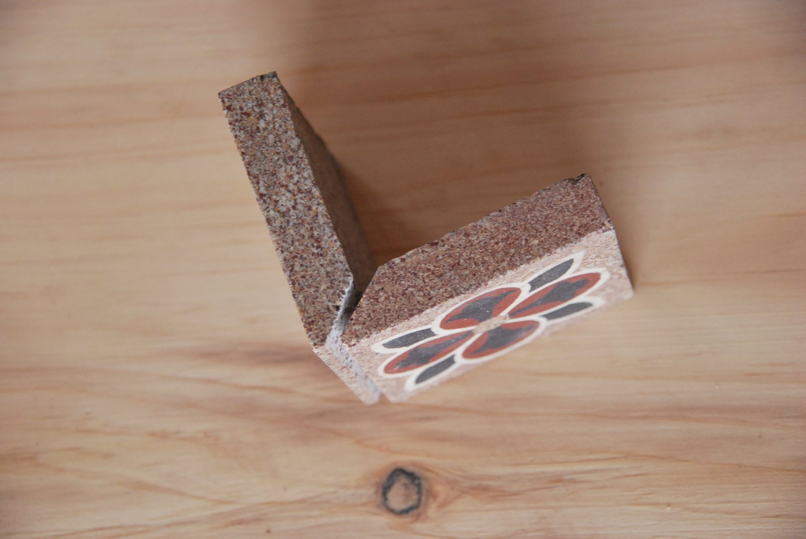
Previously unlayed concrete floor tiles made in Belgium c. 1920. These will be layed into the facing of the stove, one course below the first corbel.
The tiles that will form the corners of the row are bevelled.
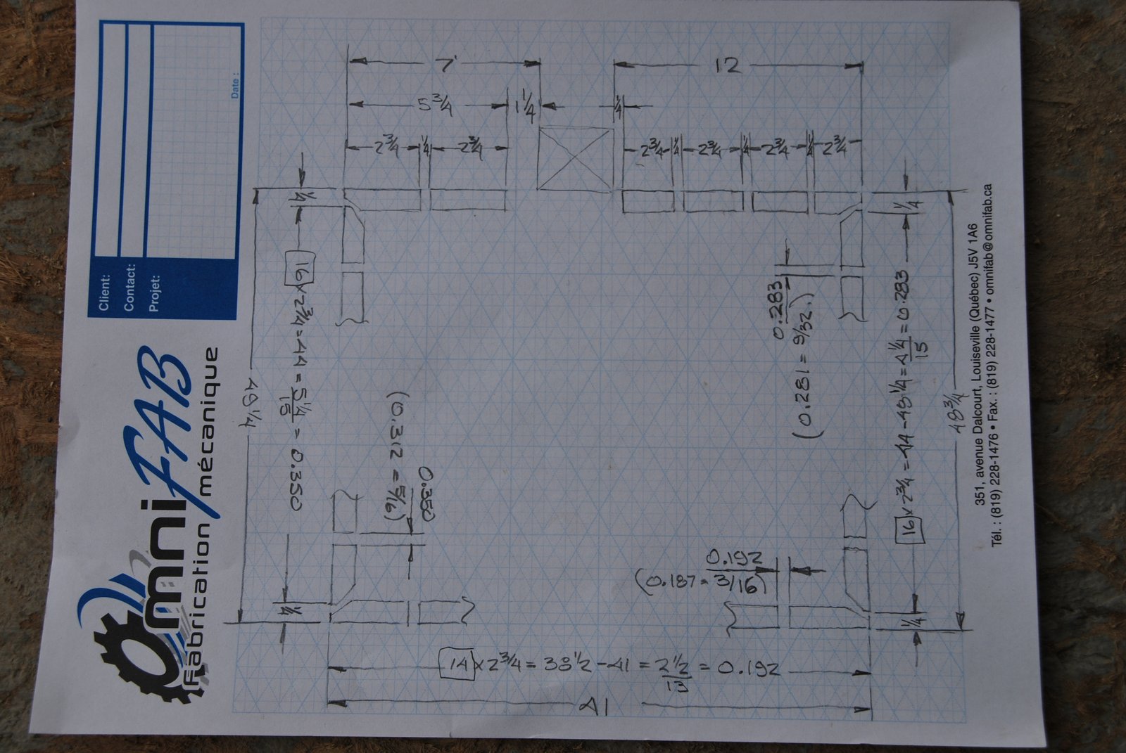
Due to having only 52 tiles, and actually needing 53 to circle the stove in a continuous band, a map was drawn to find the best lay out possible for the tiles. The missing tile was replaced by a cut piece of brick at the end of the row as the row is lost behind the chimney.
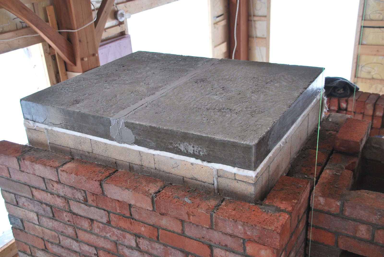
The upper surfaces of the core are gasketed with ceramic wool, before installation of the castable refractory concrete capping slabs. The wool acts as a smoke gasket and slip joint allowing the slabs to slide during expansion and not to drag the core. The gasket also helps assure even contact between the two surfaces thus avoiding pressure points on the core.
The capping slabs in position. There is a joint of refractory mortar between the slabs. Due to the slabs forming a solid connection from side to side of the core expansion is not to be underestimated. Though not shown here, the slabs are gasketed where they meet the facing, with a ribbon of ceramic wool, rather than glass fibre mat. Wool, in contrast to glass mat, provides an effective smoke gasket and allows for expansion of the slabs.
The facing is layed up above the capping slabs.. As the top of the stove will be visible from a mezzanine a course of clay facing brick will be layed in basket weave bond onto the final concrete capping slab.
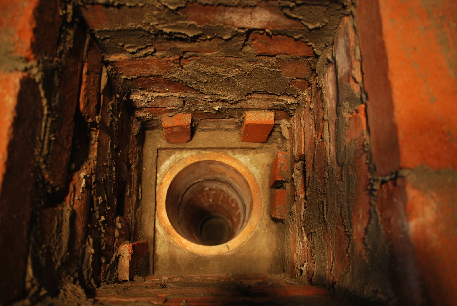
View inside the chimneys facing, just above the damper. The damper frame was layed in position and then backfilled on the back and left hand side, to stop the frame being knocked out of position by rough operation.

The damper frame in position. Note that though braced at the back and left side, the frame can expand to the right where it is gasketed, and forward out of the opening in the brick. The article Chimney Connection #14 better details the installation of a guillotine damper in this situation.
The pieces of brick layed around the periphery of the frame, contact the back fill around the tile below, and prevent the backfill around the tile above the frame, from resting on the frame. Once the next, and last, tile has been layed in place, the exposed upper surfaces of the corners of the frame will be gasketed with wool, ensuring there be no contact between the back fill around the tile above, and the frame The inside corners of some of the brick are broken off to allow the back fill around the tile to key into the facing.
Note that the weight of the backfill above the frame is not heavy enough to cause it to be compressed. Though if the backfill made direct contact with the corners of the frame, the accumulative vertical expansion of the 4 tiles and connector below, may compress the frame against the backfill above and cause the guillotine plate to bind during operation.
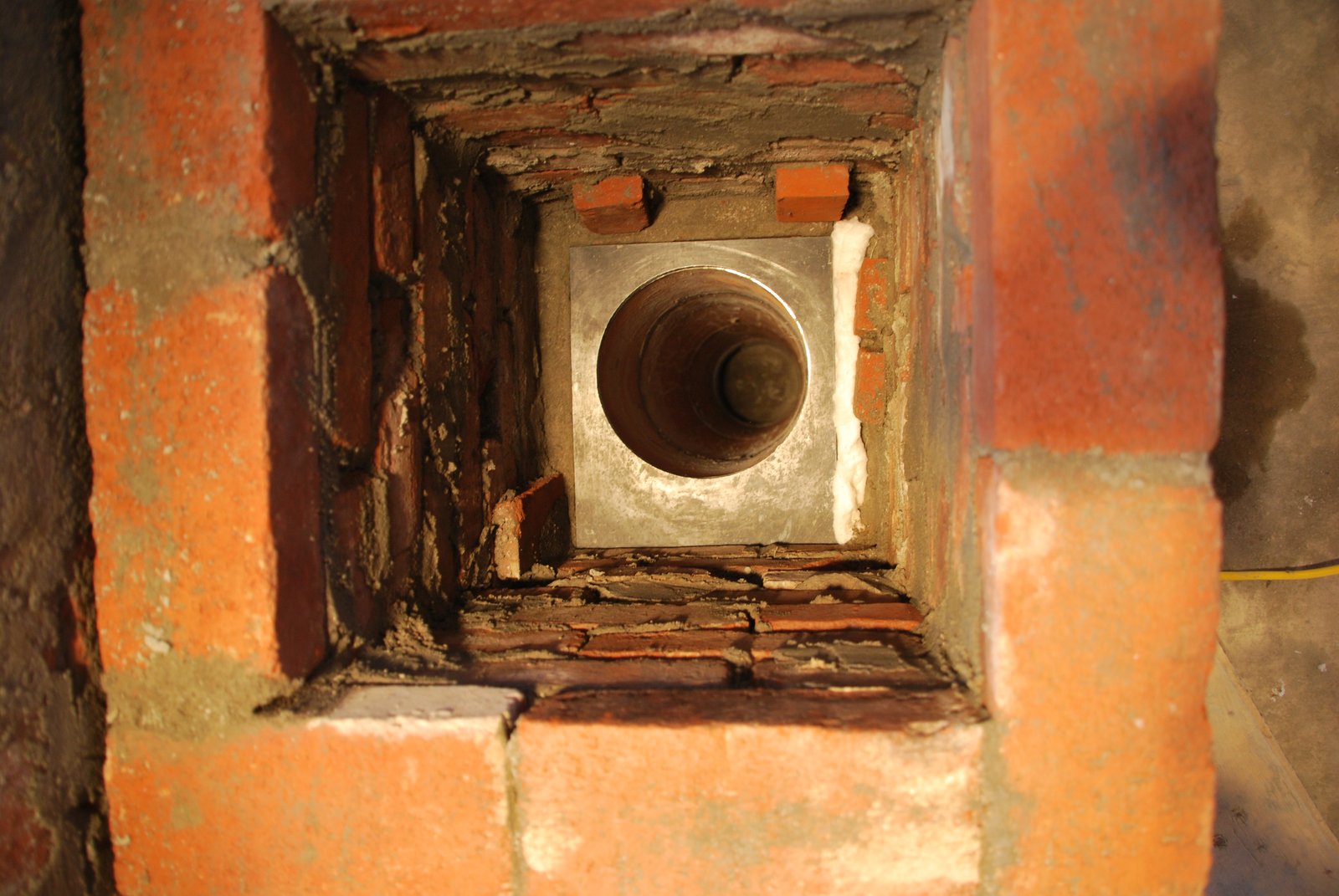
The last of the four flue tiles is layed dry onto the damper frame plate. These tiles have a male lip on one end and female lip on the opposite end. The lips must be cut off precisely to ensure an even contact between the surface of the tile and the metal surface of the damper. The upper surface of the tile is cut to arrive approx one eighth of an inch lower than the course of brick on which will rest the anchor plate. This is to avoid the whole weight of the steel flue above, resting entirely on the tile.
The last tile gasketed and backfilled, ready to install the anchor plate.
The inner surfaces of the stove's facing and the upper surfaces of the slabs are gasketed with wool. A final monolithic capping slab in common concrete will be poured onto the woollen gasket.
This gasket serves as a supplementary smoke gasket above the refractory capping slabs. Note that the sheets of wool overlap over the joint between the two slabs below.
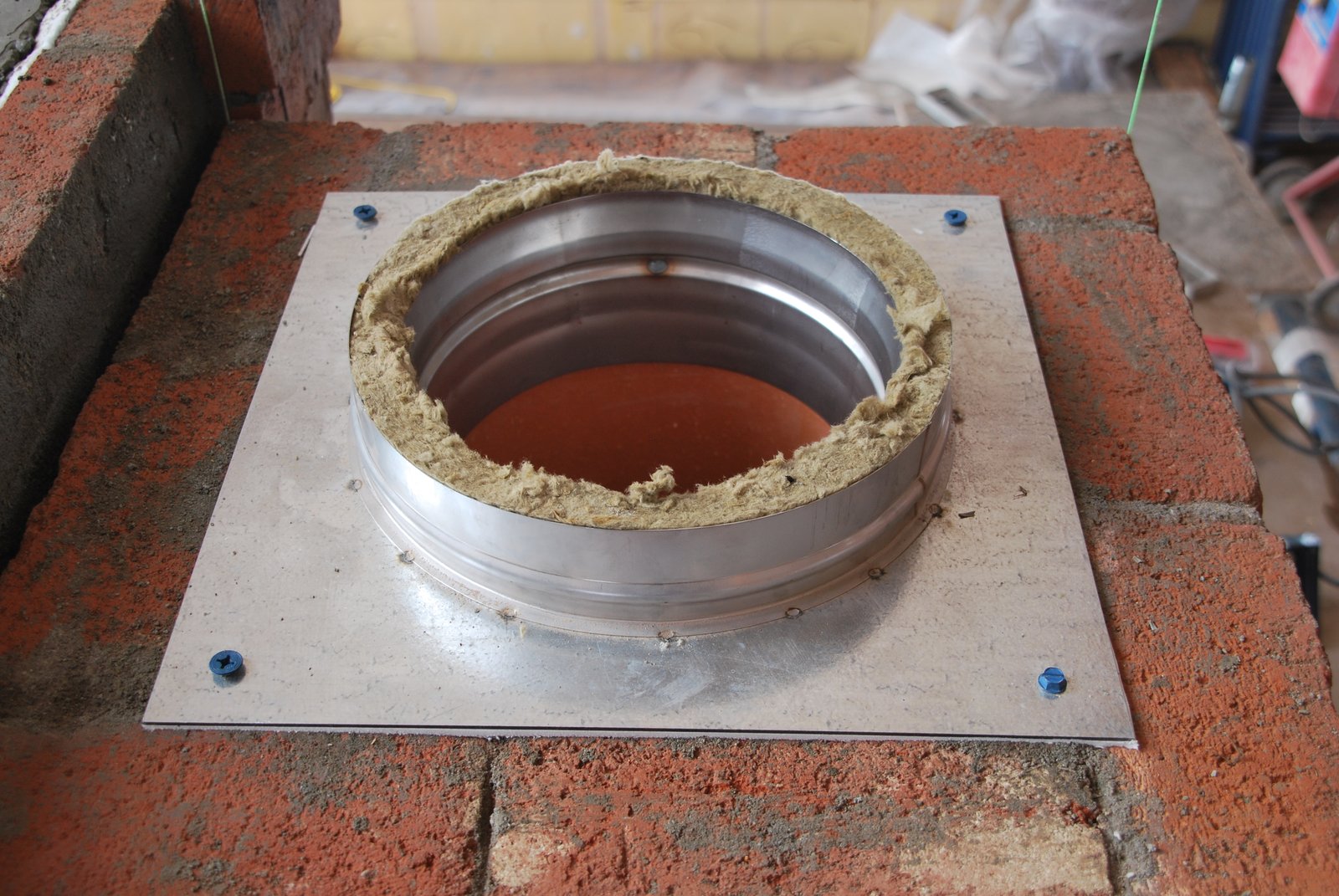
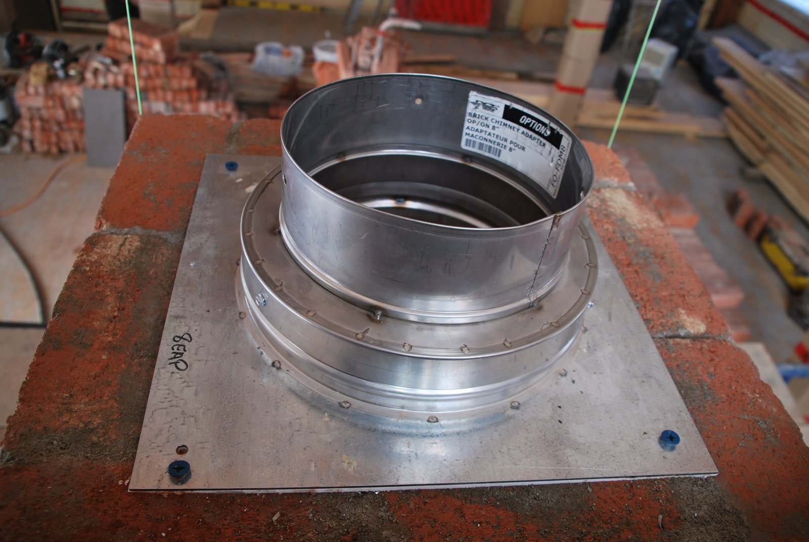
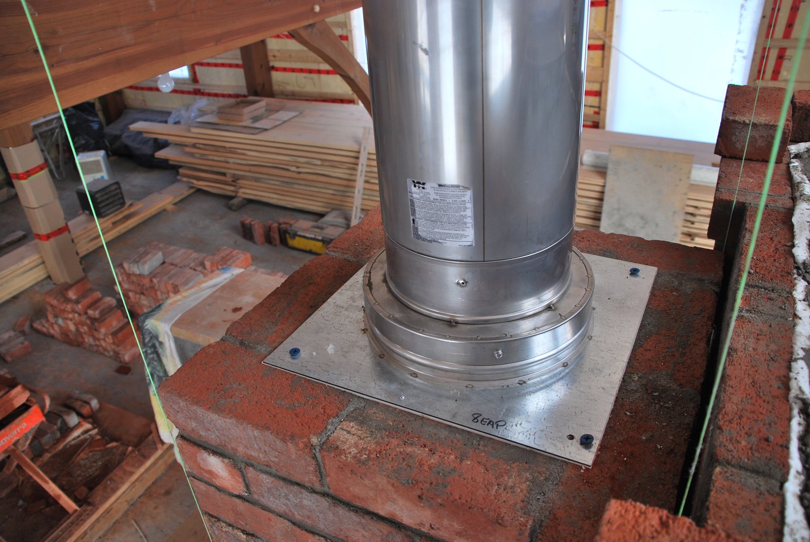
The anchor plate has a paper gasket between it and the masonry, and is held in place with concrete screws.
An adaptor allows transition from the exel 8 inch insulated anchor plate to Exel rigid liner.
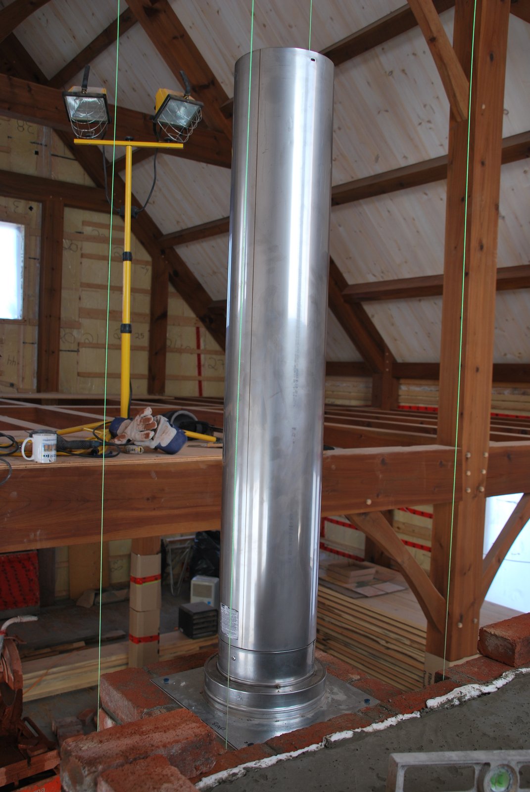
The first 4 foot length of rigid flue is riveted to the adaptor.
A thin ribbon of wool is used to gasket the outer edge of the anchor plate. As there will be 20 feet of masonry above this course it is crucial that the anchor plate has no effect on the course layed above it.
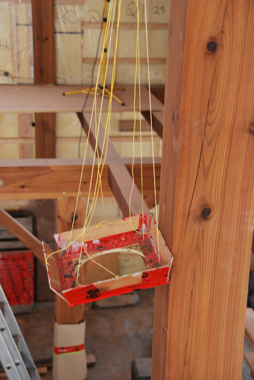
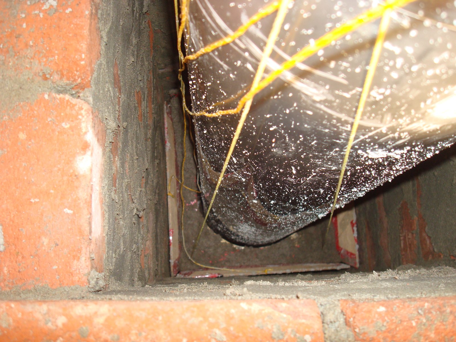
A 'Marionette' developed by the client, stops squeeze-out falling down inside the chimney onto the anchor plate.
The marionette in position.
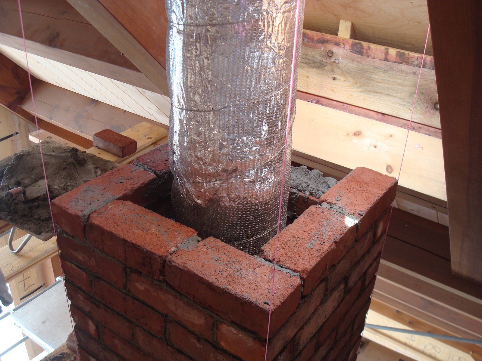
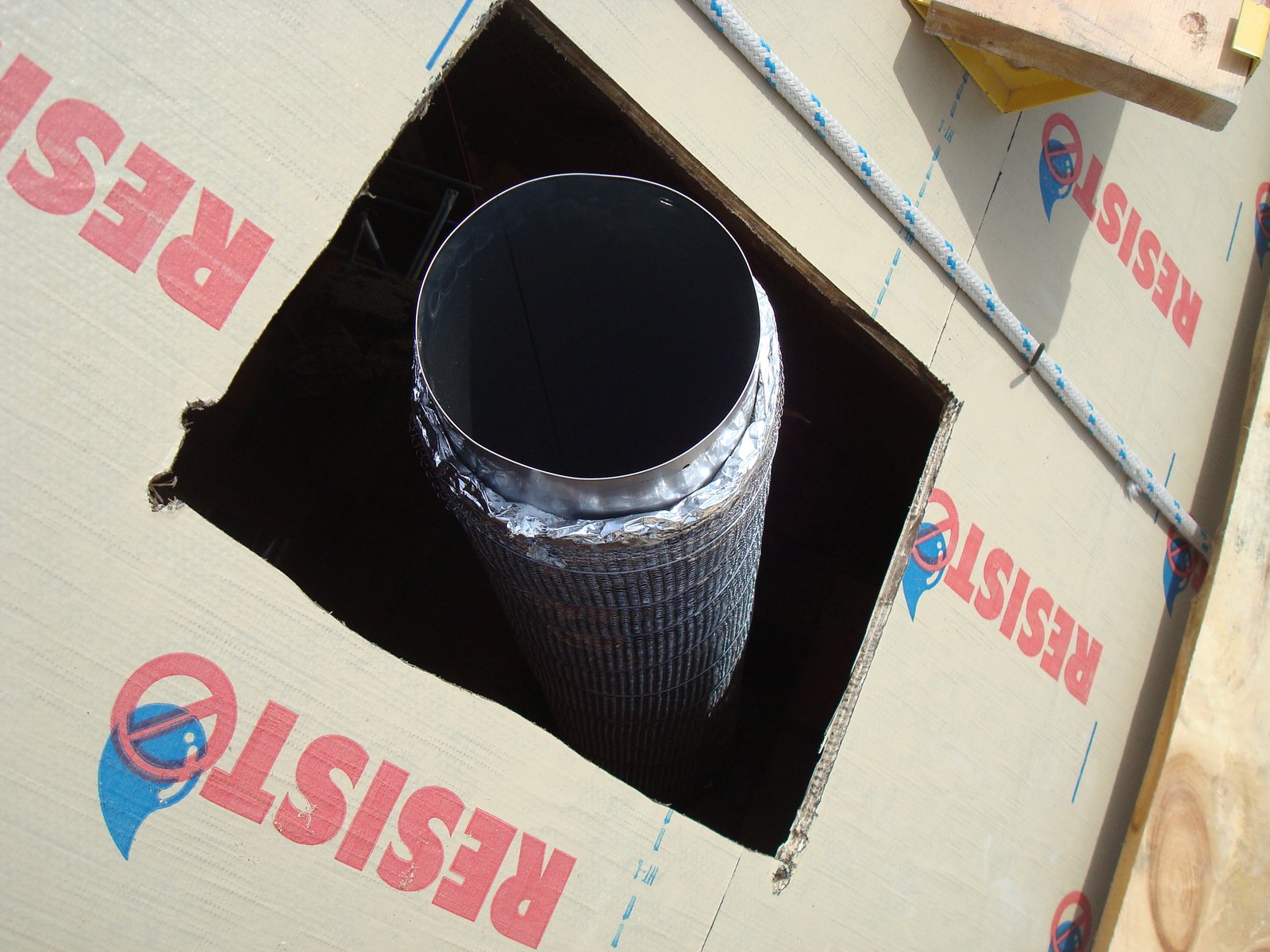
Just before the chimney passes through the roof line the flue liner is wrapped in foil backed ceramic blanket. The blanket is protected and held in position by a stainless steel mesh sock, bound with stainless steel wire.
Insulating the liner is not an obligation in this situation. It has been done only to keep the portion of the flue on the outside of the house warm. This is to avoid excessive condensation on the inside of the liner.
Pilot hole in the roof. The masonry of the chimney will be layed up to the roof from the inside, before cutting the actual opening for the chimney.
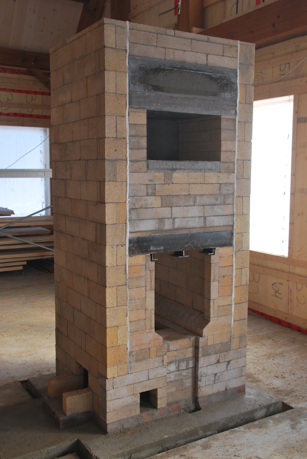
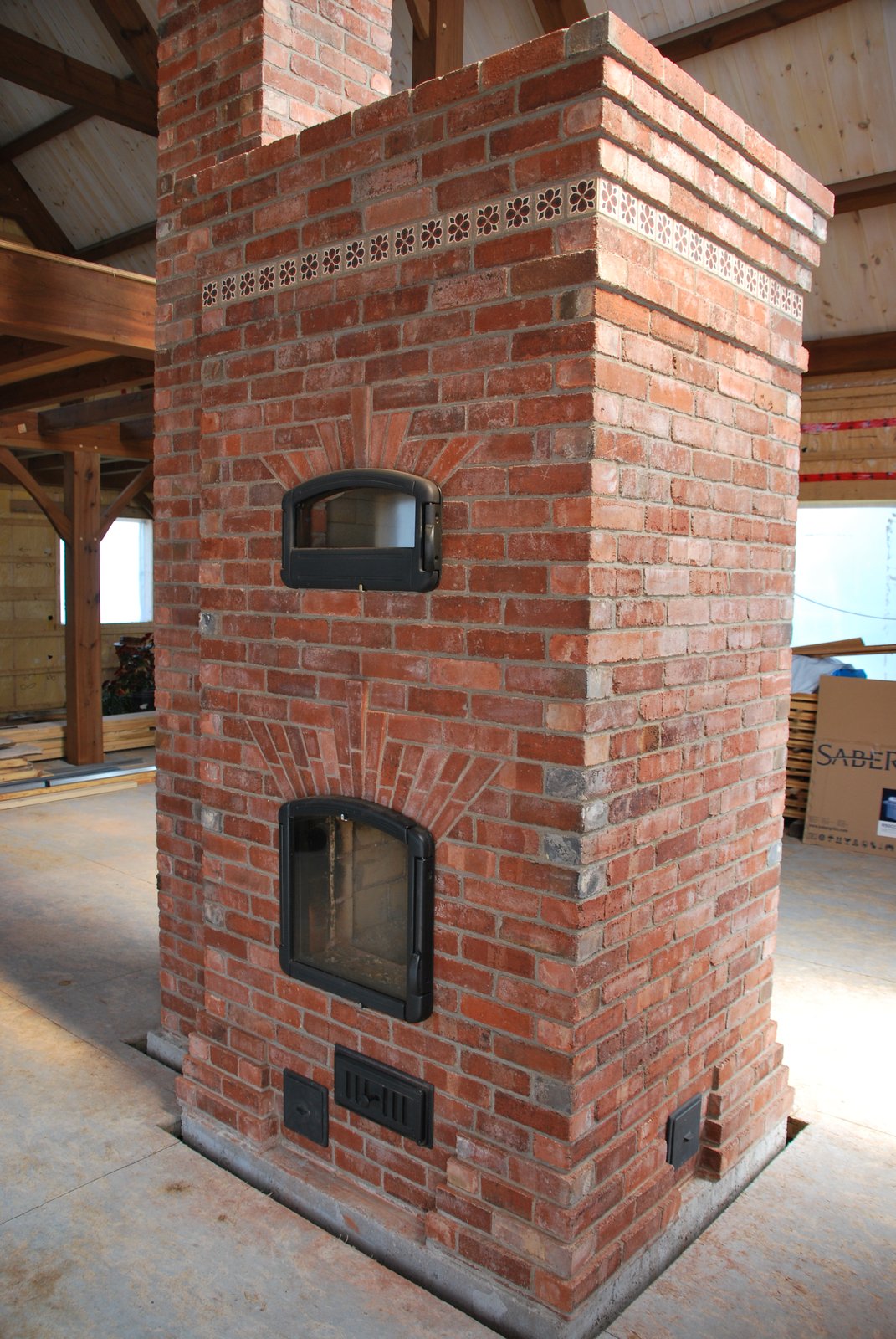
The following two images detail the facing of each side of the see through fire box.
The centred opening is for the primary air intake and the small opening to its right a supplementary underair intake. The corbel is symmetrical.
As the chimney covers the left side channel, and a the access opening in the chimney is to high to allow effective access to the channel through the chimney connection, an access opening for the channel has to be located in the face. The primary air intake opening is off centre and the corbel slightly asymmetric.