Chimney Connection #14
These notes detail the connection of an insulated steel prefabricated chimney to a North American contraflow stove in La Beauce QC.
The system consists of 8 feet of masonry chimney containing an 8 inch ID clay tile, onto which an 8 inch anchor plate is located in order to transition to steel prefabricated chimney.
This provides:
A direct manually operated shut off damper at 6 feet.
The longevity, efficiency, and ease of maintenance, and installation, of a prefabricated chimney.
Compatibility of the 8 inch flues of each portion, in the optimum flue format for a large masonry stove.
The longevity, efficiency, and ease of maintenance, and installation, of a prefabricated chimney.
Compatibility of the 8 inch flues of each portion, in the optimum flue format for a large masonry stove.
Materials:
Refractory Brick
Alsey Smithfield MD
Refractory Mortar
Mount Savage Super High Mull
Castable Refractory Concrete
Mount savages Heatcrete 421 esc
Ceramic Wool
Thermal Ceramics Superwool 607 HT
Ceramic Paper
Vesuvius Rollboard
Facing
Recycled Clay Brick from 1910
Facing Mortar
King 116 Type N
Prefabricated Steel chimney
ICC Exel 8 inch
Fiberglass Mat
450g Chopped Strand Mat

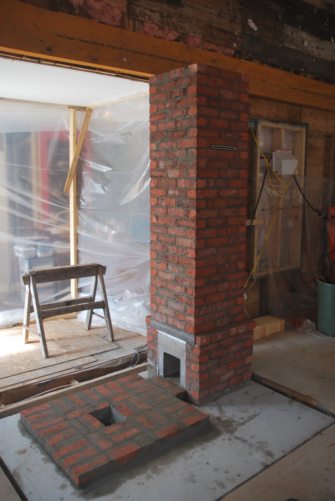
The chimney will be located just inside the new extension to an existing house. The total height within the living area will be 12 feet. Consisting of 8 feet of masonry chimney, and 4 feet of insulated steel chimney. The stove will be 8feet high. There will be 13 feet of insulated chimney above the point at which it exits the roof, giving a total chimney height of 21 feet.
Note: In this situation, due to the chimney having to pass through the roof before the tin was installed, the chimney was built prior to the core and facing.
Normally the core would be built first, and then the chimney layed up with the facing, making things considerably easier.
Note: In this situation, due to the chimney having to pass through the roof before the tin was installed, the chimney was built prior to the core and facing.
Normally the core would be built first, and then the chimney layed up with the facing, making things considerably easier.
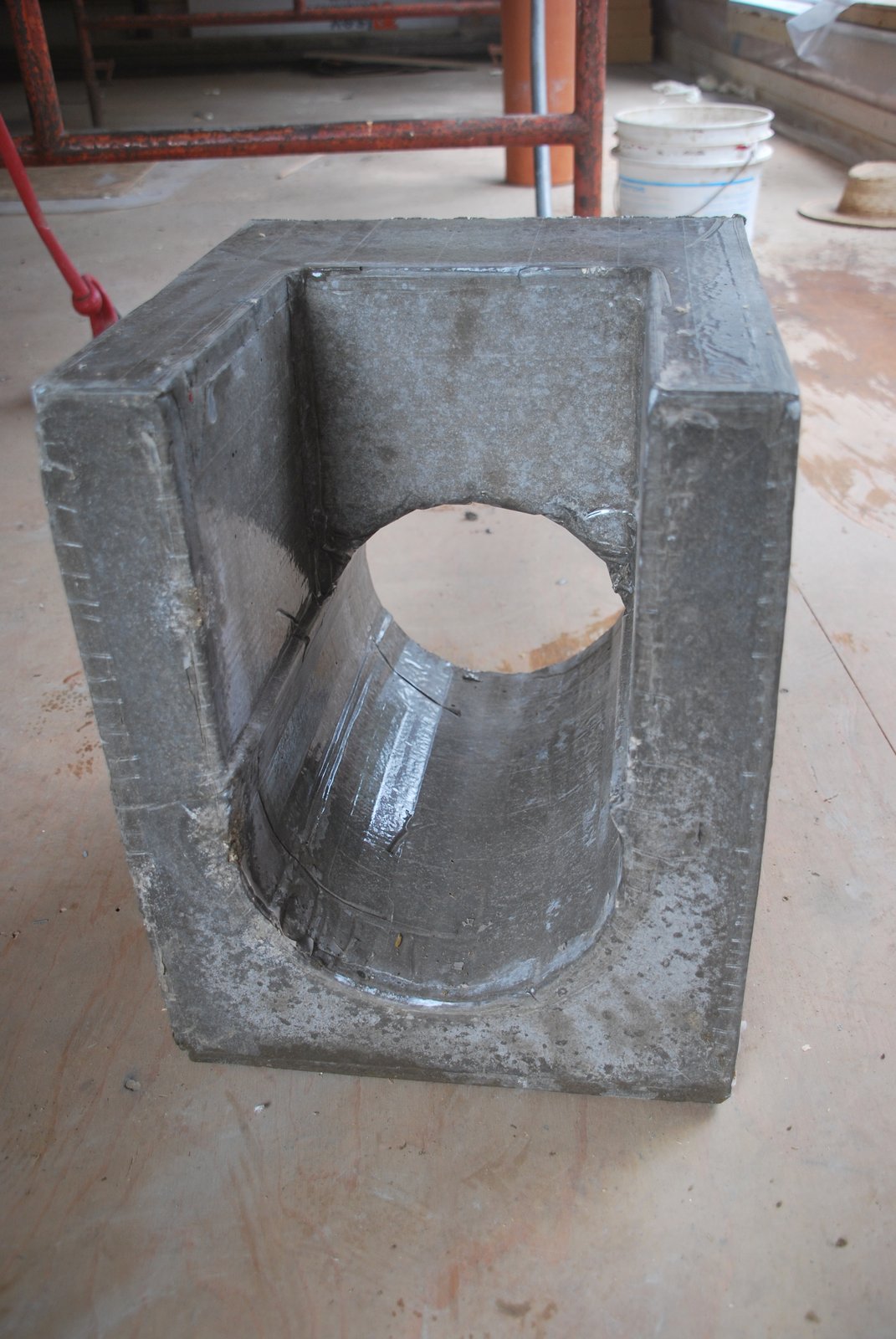
The chimneys connector is of castable refractory concrete. It allows the construction of an 8 inch square refractory brick connection from any manifold to the 8 inch square opening in its face.
An 8 inch ID flue tile sits on top of an 8 Inch ID opening in the connectors adjacent face.
Note: The primary function of the connector is to provide a robust, smooth transition piece between square and round, on to which will rest the chimneys flue.
The primary consideration at this point is to have something strong yet not too bulky, in order that it fit within the modular wrap of the facing brick. Building the connection in fire brick shiners is possible, though as most HTCs are water soluble if not fused, there can be a risk of condensation falling down the chimney, into its base, dissolving the mortar and potentially effecting the connections stability. Cured castable is not effected by moisture, and has great compressive resistance.
Arriving at a round opening with refractory brick is also difficult and time consuming. Custom cutting two round flue tiles to connect perpendicular to each other would be tricky and effect the structural integrity of the vertical clay tile, especially if a clean out opening were cut opposite the connections opening. And there would still be a necessity to transition from round to square at the manifold.
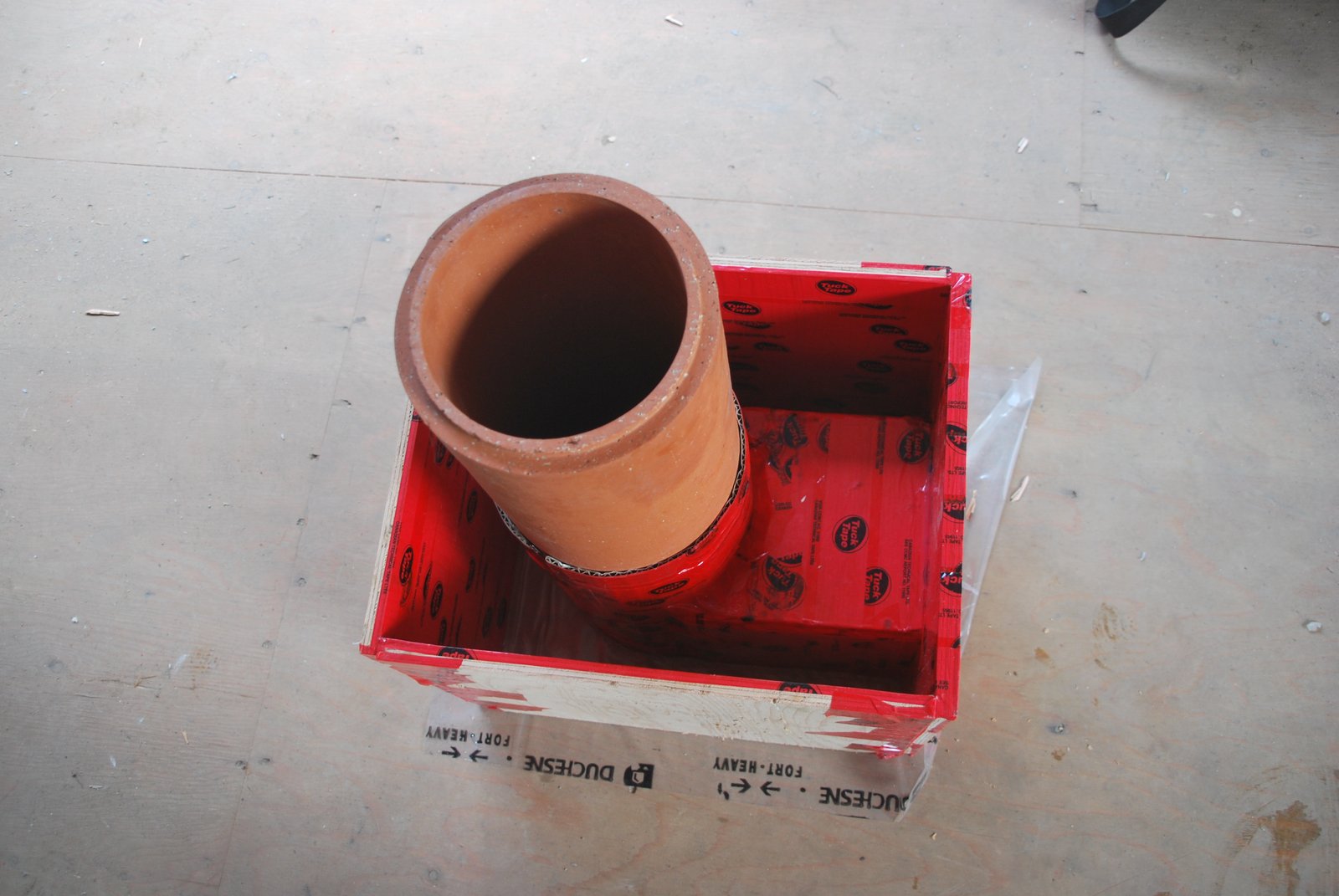
The connector is cast into a mold made from ply wood and a 6 inch ID flue tile. All surfaces that will be in contact with the castable are taped, and joints sealed with silicone.
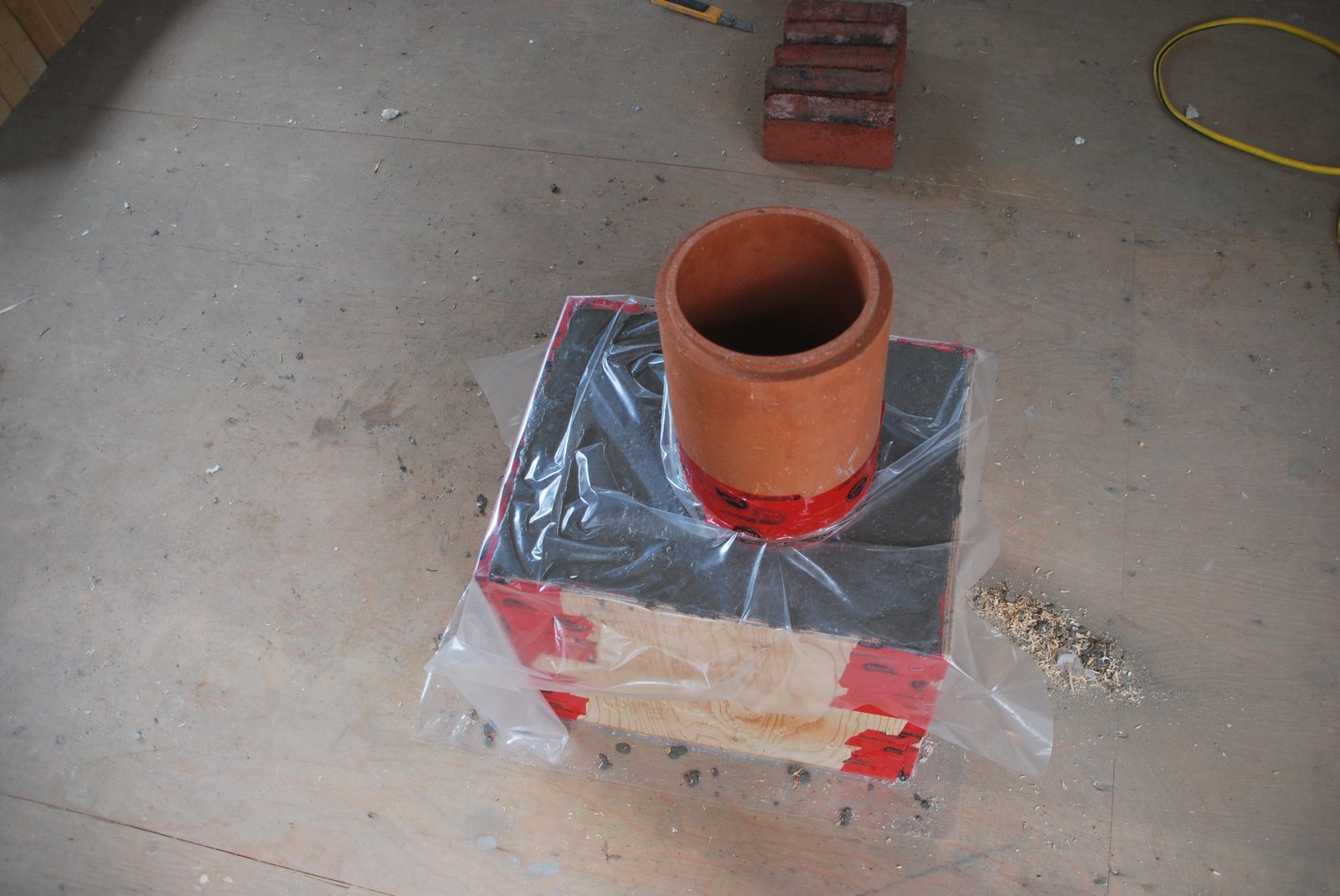
The castable is poured and allowed to cure.
Note that the 6 inch ID flue tile, when gasketed with one sheet of corrugated cardboard, can easily be removed whole, and leaves an opening of exactly 8 inches ID
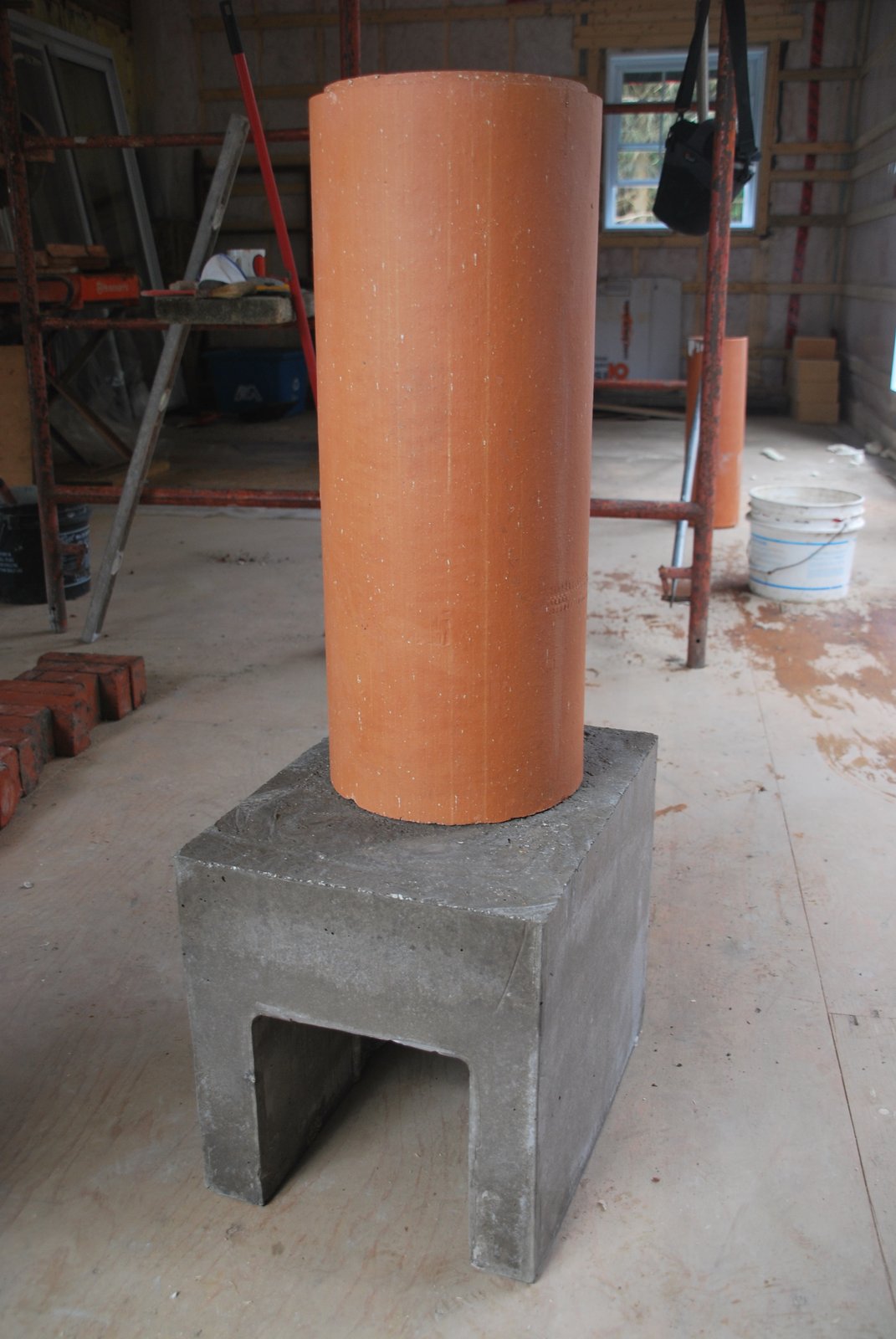
The connector. Pouring this took 110 lbs of castable.
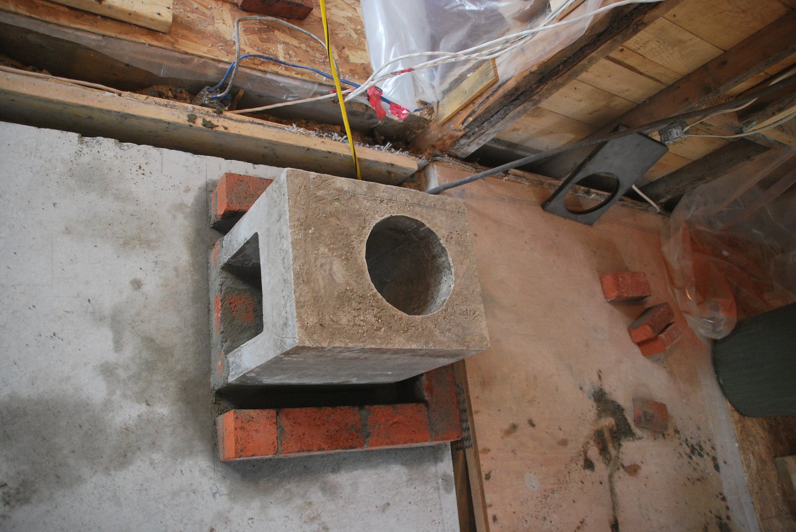
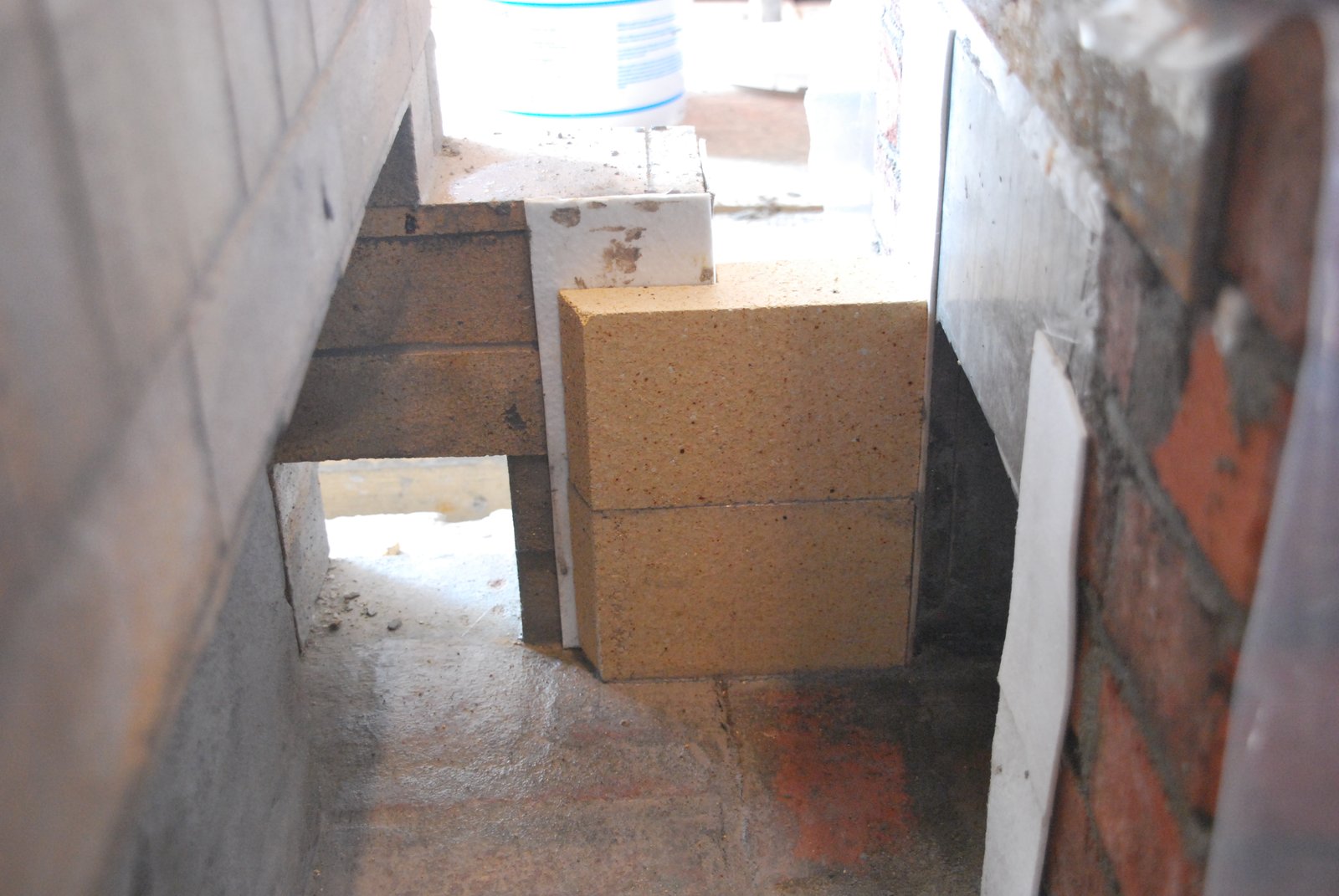
The connector layed into position onto a base of clay brick.
Note: The connector is 13 inches wide which allows it to fit inside a brick chimney with exterior dimensions of 21 x 21 inches. In this instance, the first 7 courses of facing brick around the base of the chimney will form an expanded skirt 27 inches wide. The function of the skirt is to match a similar detail around the base of the heater, and is of no relevance to the chimneys connection.
Note: The connector is 13 inches wide which allows it to fit inside a brick chimney with exterior dimensions of 21 x 21 inches. In this instance, the first 7 courses of facing brick around the base of the chimney will form an expanded skirt 27 inches wide. The function of the skirt is to match a similar detail around the base of the heater, and is of no relevance to the chimneys connection.
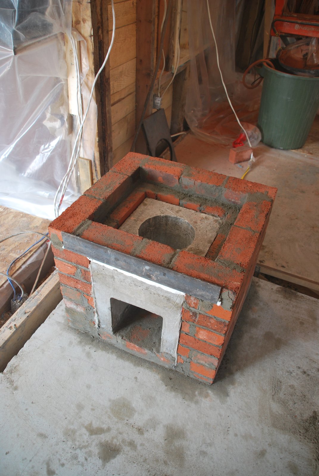
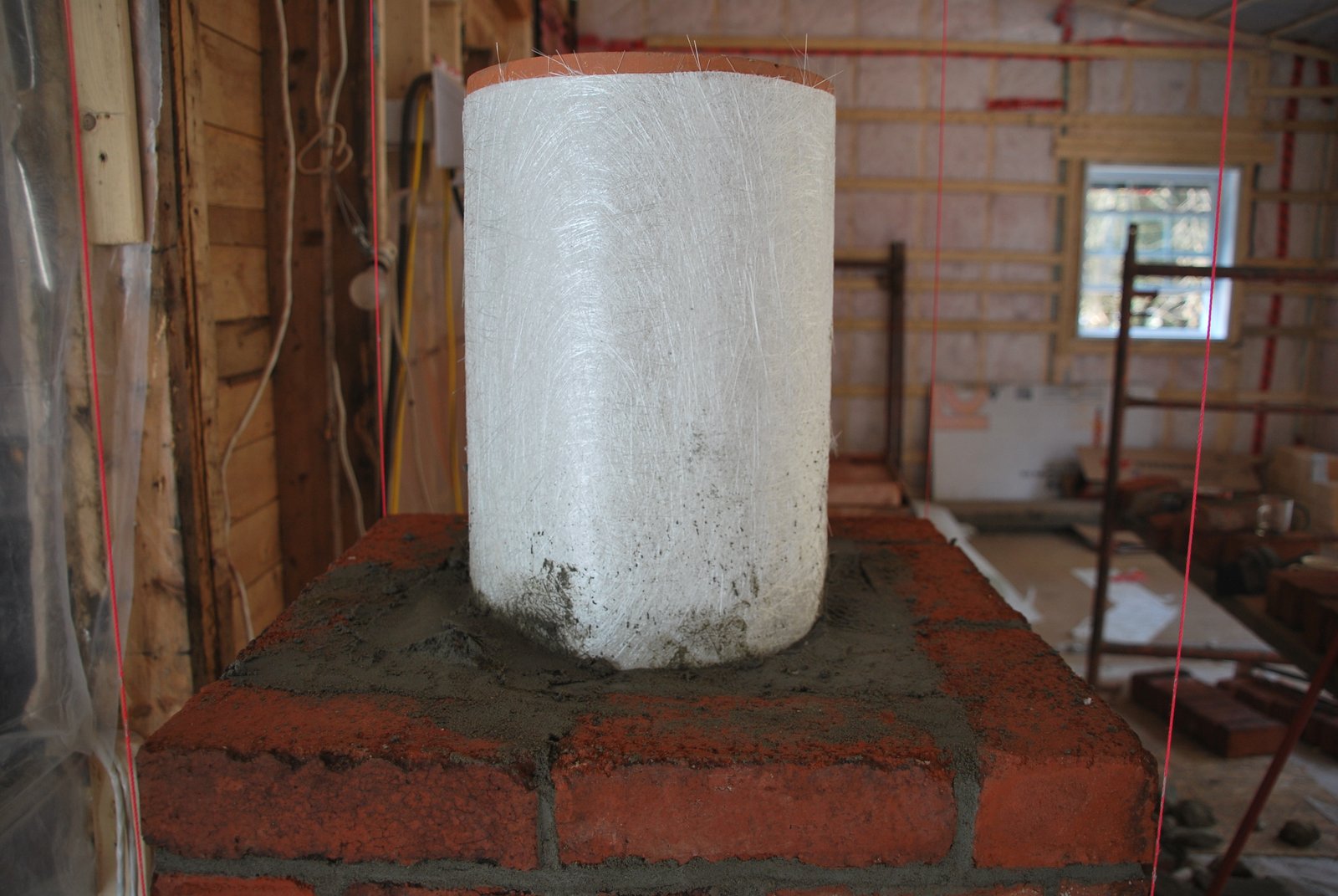
The connection is gasketed with 2 sheets of fibreglass mat before being faced. An angle iron lintel bridges the opening in the facing.
Detail. The square recess in the first course of brick (partially visible at the bottom of the inside of the connection) is to catch any falling condensation and prevent it flowing out of the base of the chimney towards the fire brick portion of the connection between the manifold and the connector.
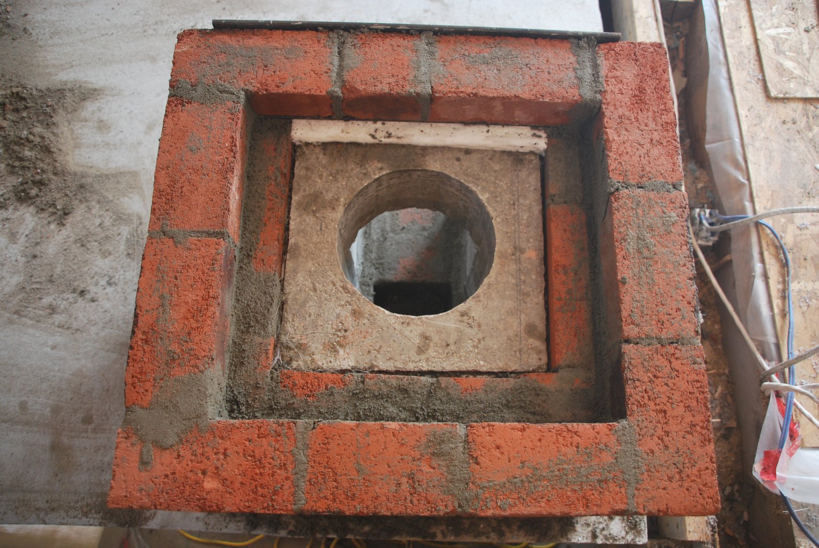
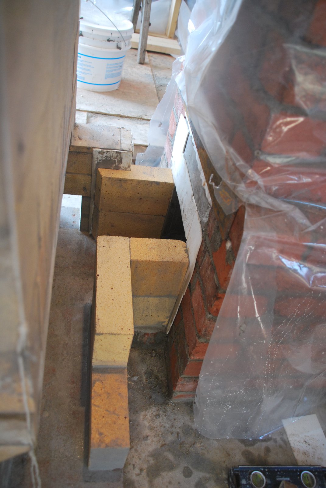
The periphery of the upper surface of the connector is gasketed with wool, before backing brick is layed. Just enough room is left to insert the first clay flue tile. Once the facing of the chimney is retracted to 21 x 21 inches, concrete will be poured between the gasketed flue tile and the facing brick.
The position of the backing brick allows the concrete fill to rest upon the facing, and not the upper surface of the connection.
Note: This manner of working means that like the refractory core, the whole of the chimneys flue is free floating, allowing lateral and vertical expansion.
At this point in the smoke path, under normal operating conditions, temperatures will be low, and expansion, particularly lateral expansion, negligible. Though thermal expansion is easier to deal with before, rather than after, the event.
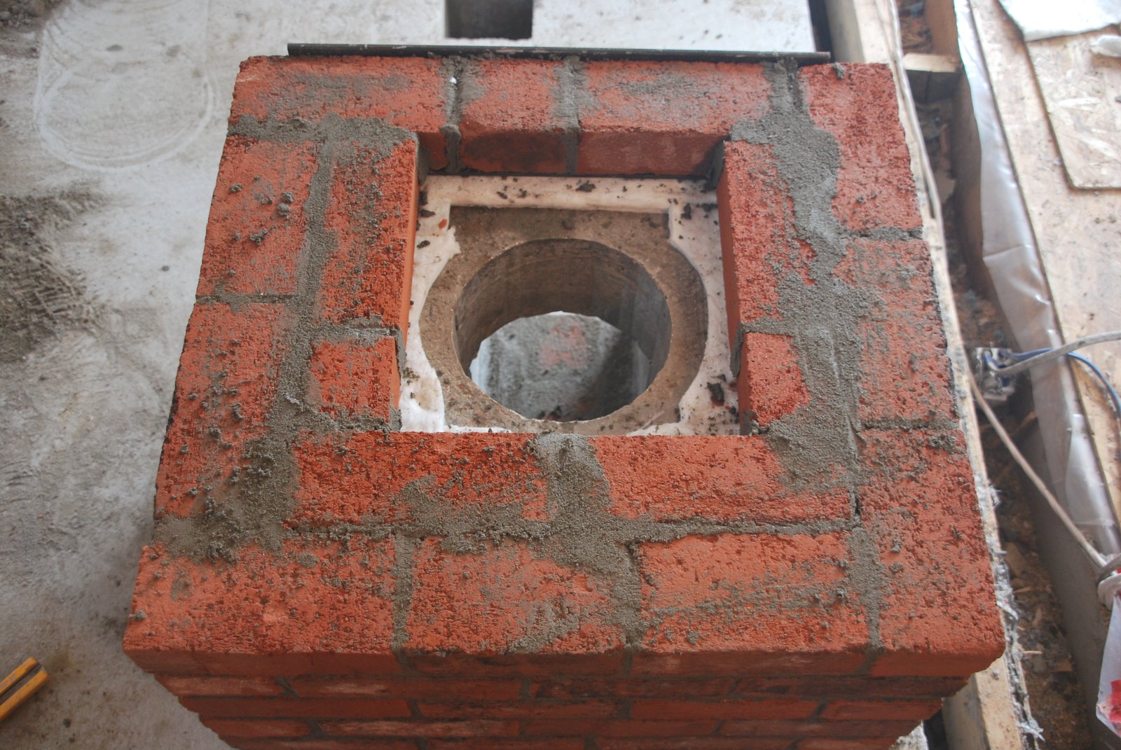
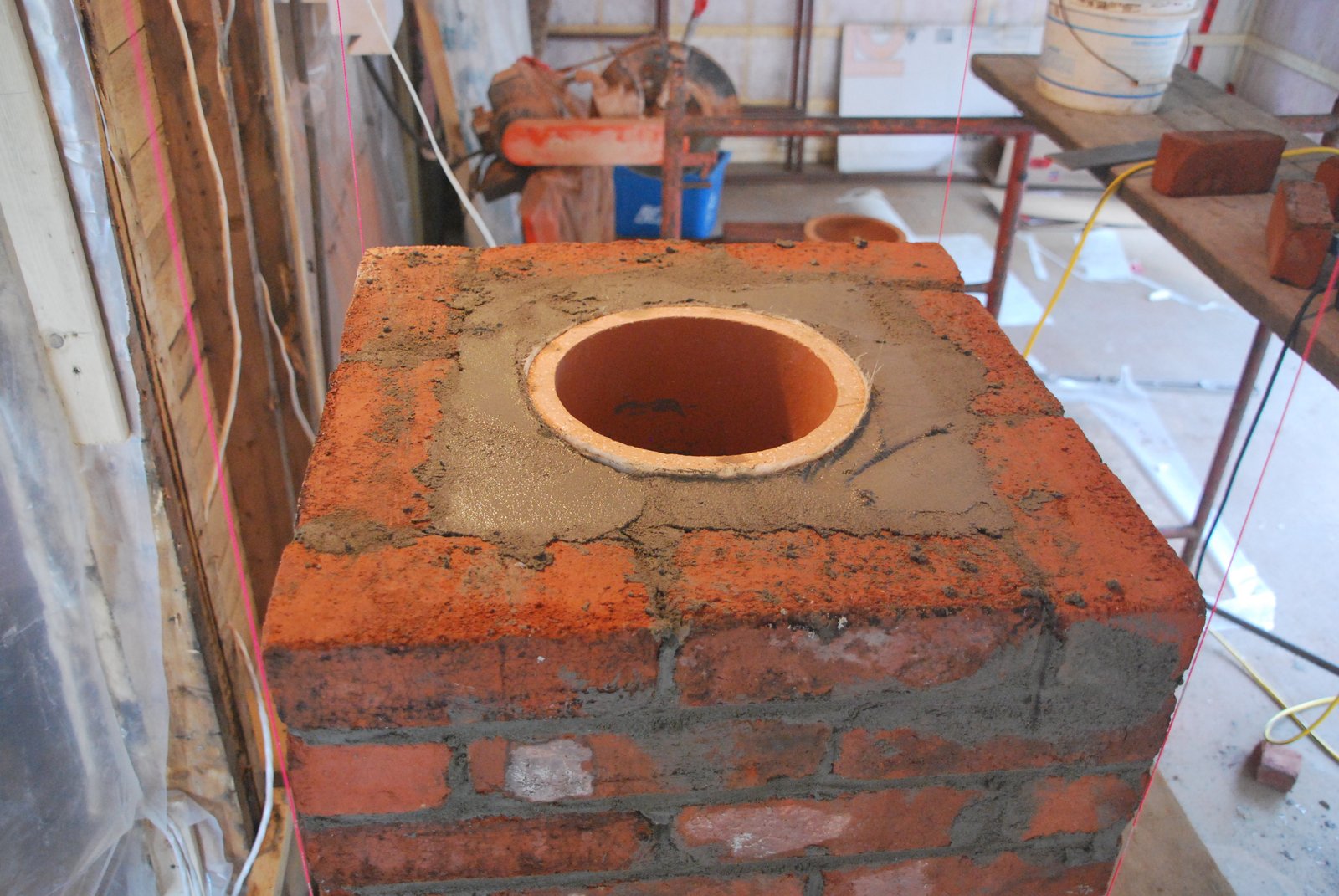
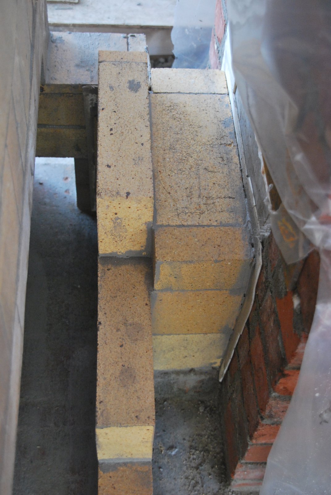
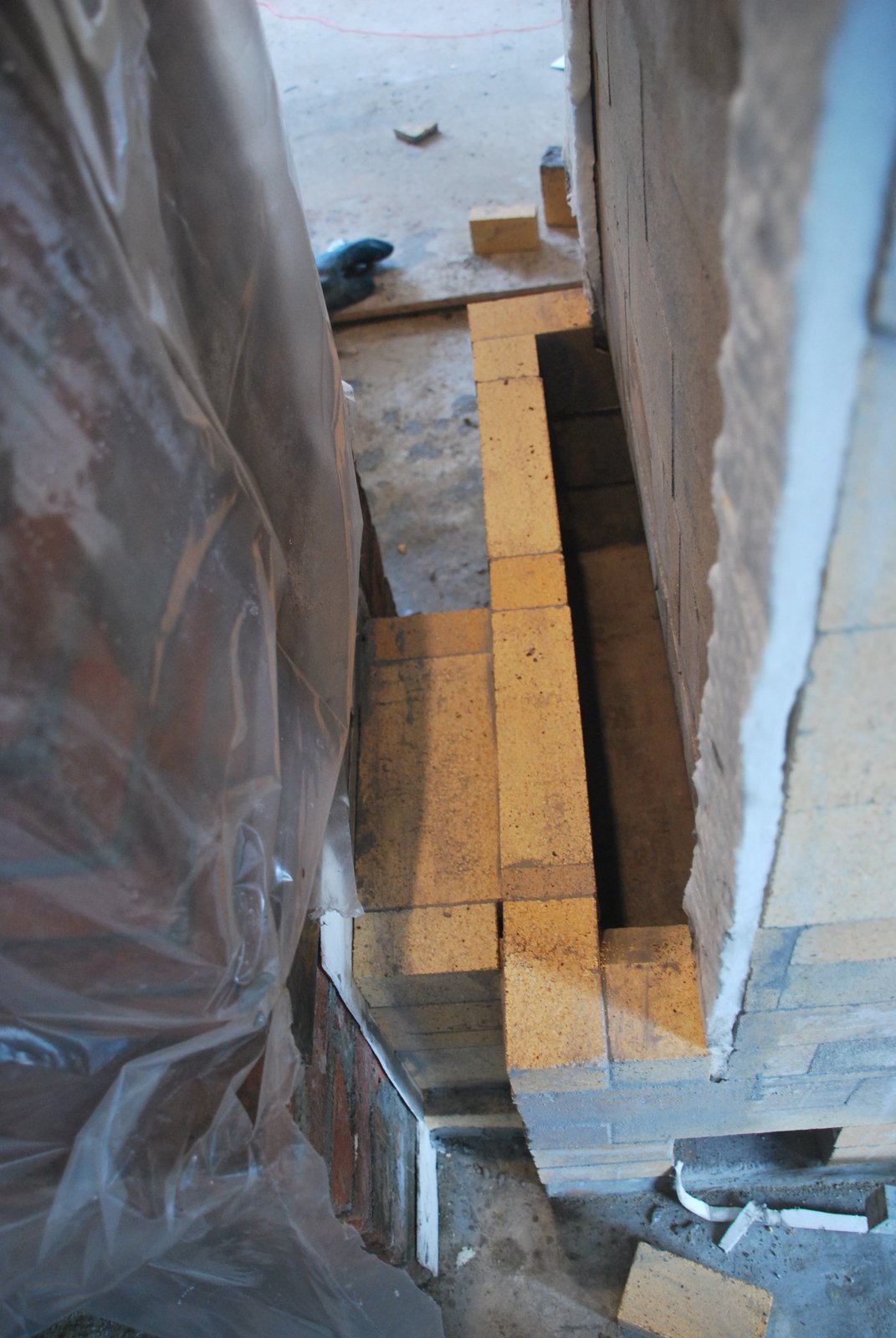
The chimney with its facing retracted to 21 x 21 inches, after course 8.
The gasketed tile is layed first and the concrete backfill inserted 2 courses at a time as the facing is layed up. Back filling each 2 courses is preferable to slushing the whole 2 foot deep void once the facing has been layed up to the top of the tile. The slump force of high lift grouting may dislodge or compress gasketing.
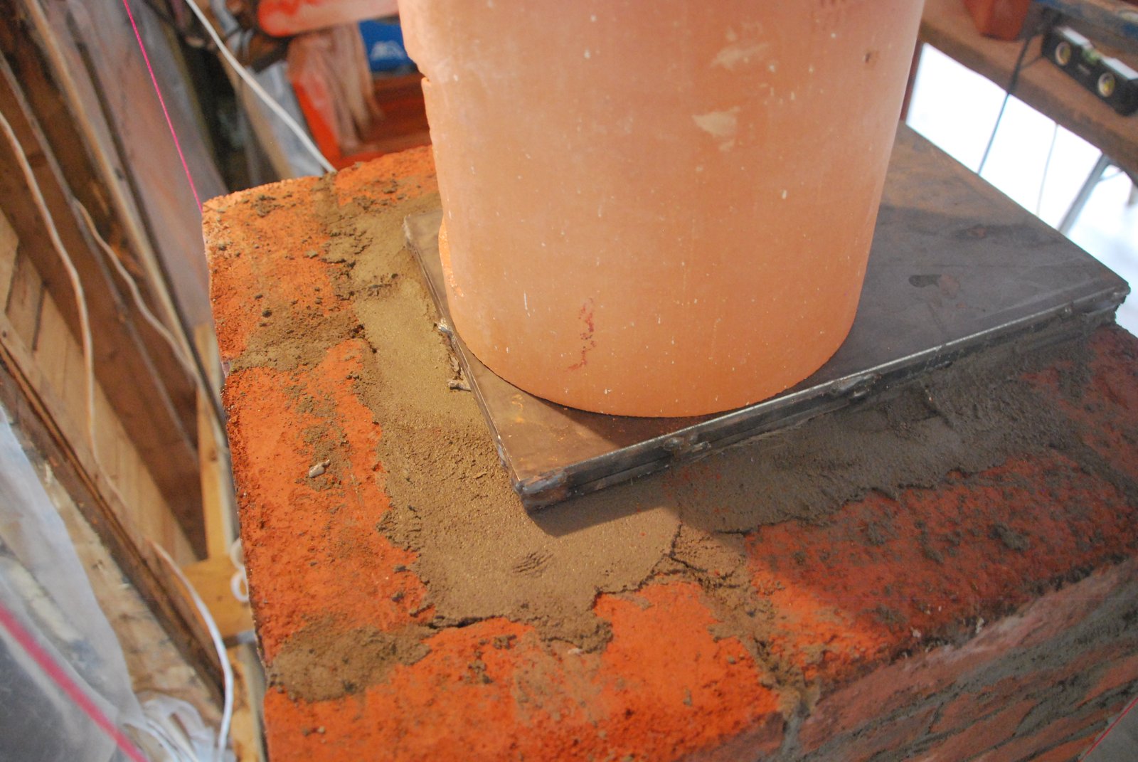
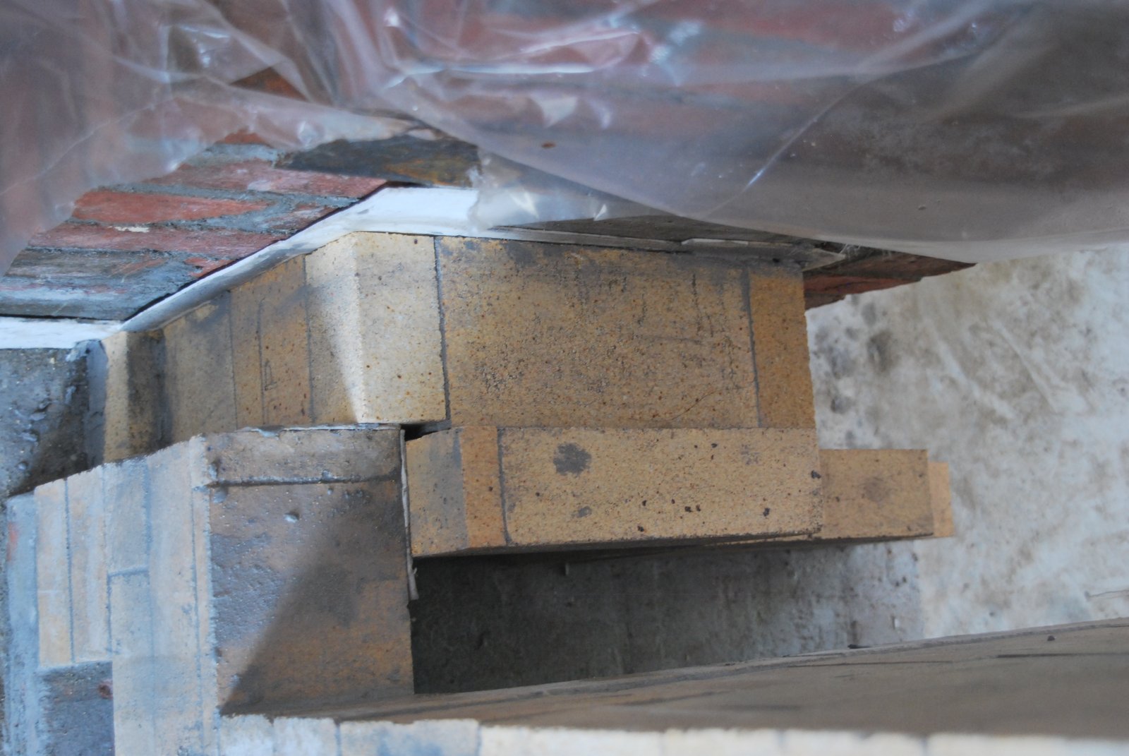
A clay tile is cut to arrive 1/8th of an inch above the top of the last course of facing brick.
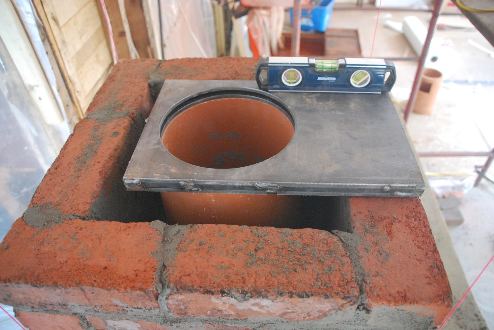
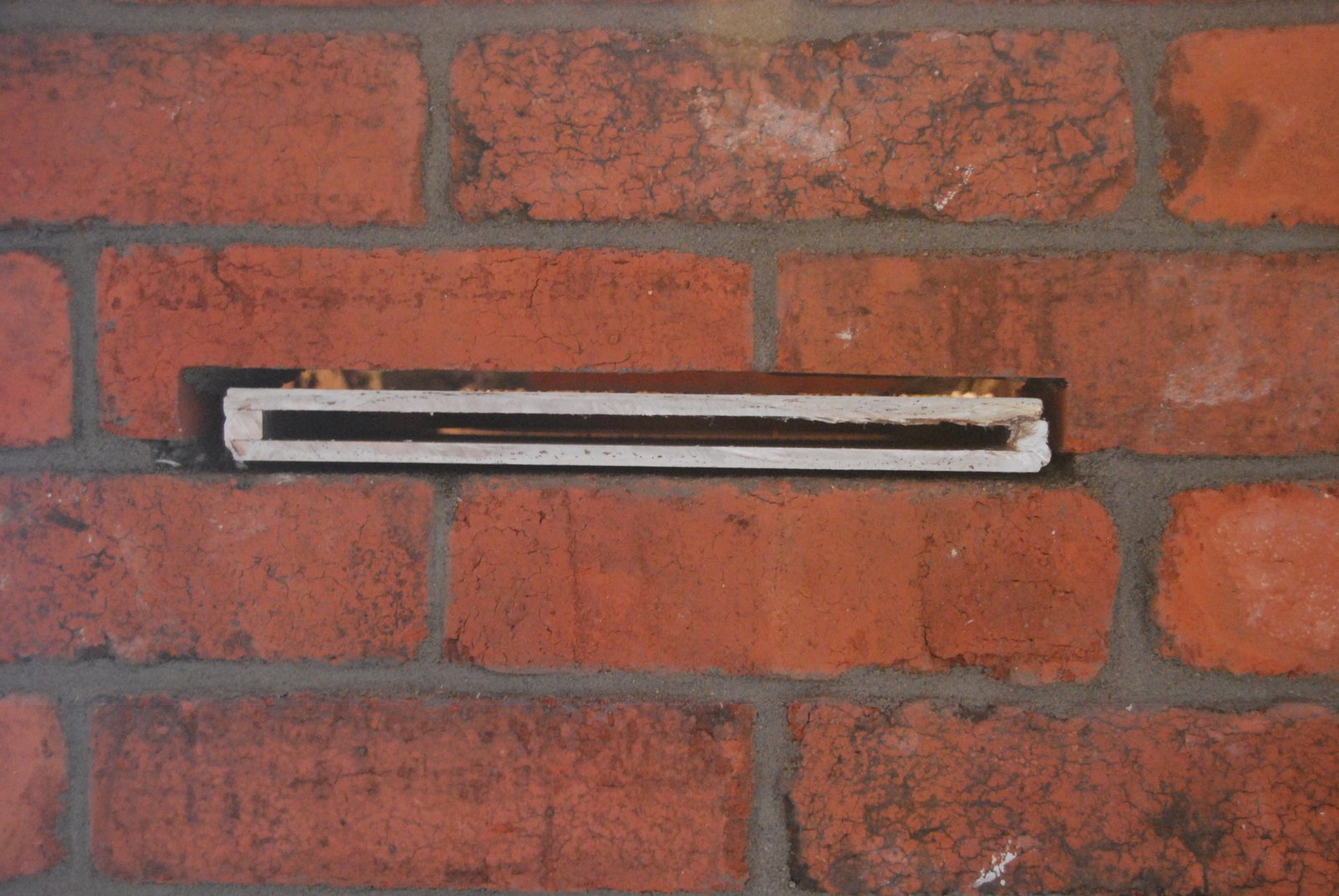
The damper frame plate placed in position.
The tile is cut so that the upper surface drops back, slightly away from the face of the chimney. This will have any condensation that falls down the chimney on to the guillotine plate, run back into the flue and not along the plate and down the exterior of the facing.
The tile is cut so that the upper surface drops back, slightly away from the face of the chimney. This will have any condensation that falls down the chimney on to the guillotine plate, run back into the flue and not along the plate and down the exterior of the facing.
Note: The compressive force of the flue tiles above the damper is exerted upon the 1cm square bar between the two plates along the periphery of the frame. This makes binding of the damper unlikely. Excepting the 1cm square bars, all other steel used in the dampers construction is one quarter inch thick.
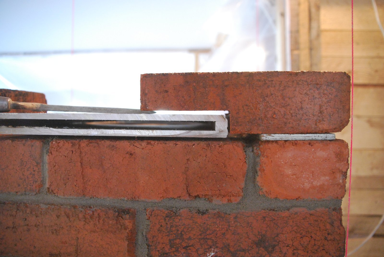
As the facing of the chimney will rise only another 6 feet, the opening in the chimney face for the damper frame and plate, will be bridged with out using a flat bar lintel. This will allow a neater opening and be easier to set up.
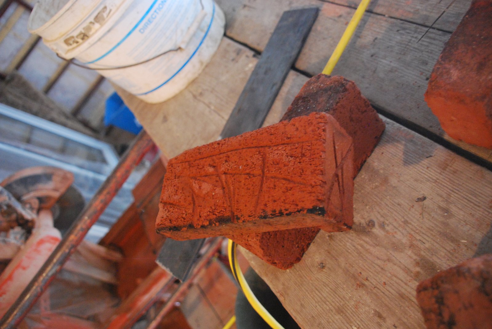
The brick used to bridge the opening have been scared and washed to allow maximum tensile bond between the first courses over the opening.
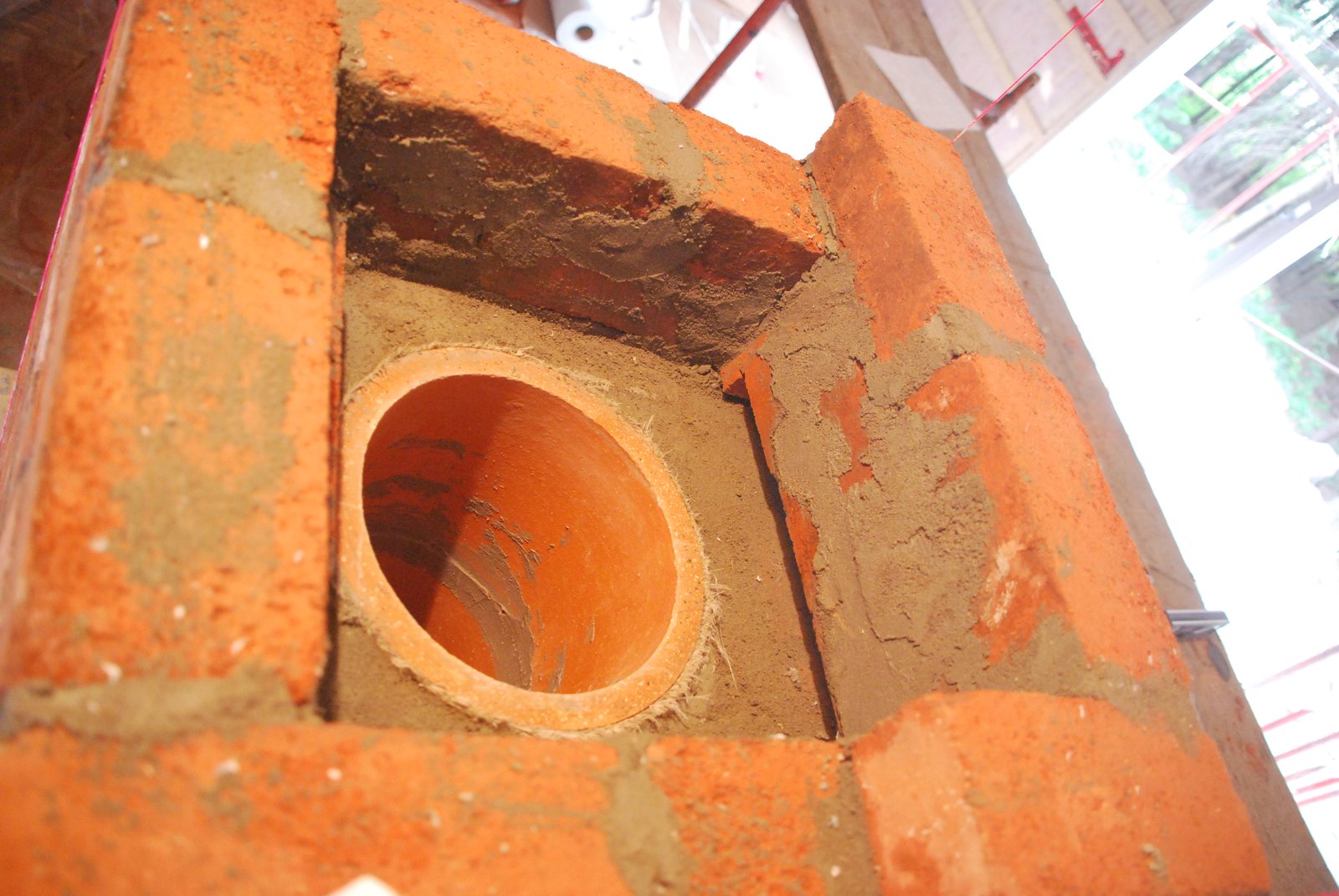
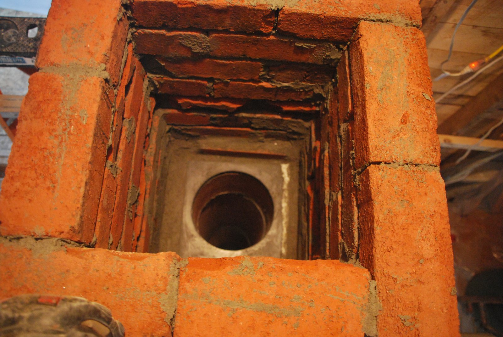
View inside the chimney after the opening, at right, has been bridged.
The frame in its final position. Note that it too will be free floating.
The damper frame is braced with solid masonry at the back, and on one the right side. This allows the frame to expand forwards, and to the left, while being held in position. The masonry in contact with the back of the frame stops the frame being knocked out of position, by the guillotine plate as it is pushed in to close the damper.
Note: Both the tile below and above are ground perfectly level, and layed dry to the plates they contact.
Note: Both the tile below and above are ground perfectly level, and layed dry to the plates they contact.
View just before the insertion of the last gasketed clay flue tile.
Note that the brick of the first courses above the damper frame, have had their back corners broken off. This is to allow the concrete backfill between the flue and facing, to key into the facing and not exert any pressure on the corners of the damper frame. Once the last tile is in position, any areas of exposed metal frame are gasketed with wool, and a ribbon of wool wraped around the bottom of the tile where it contacts the frame, before back filling. (There is no image of this.)
Note that the brick of the first courses above the damper frame, have had their back corners broken off. This is to allow the concrete backfill between the flue and facing, to key into the facing and not exert any pressure on the corners of the damper frame. Once the last tile is in position, any areas of exposed metal frame are gasketed with wool, and a ribbon of wool wraped around the bottom of the tile where it contacts the frame, before back filling. (There is no image of this.)
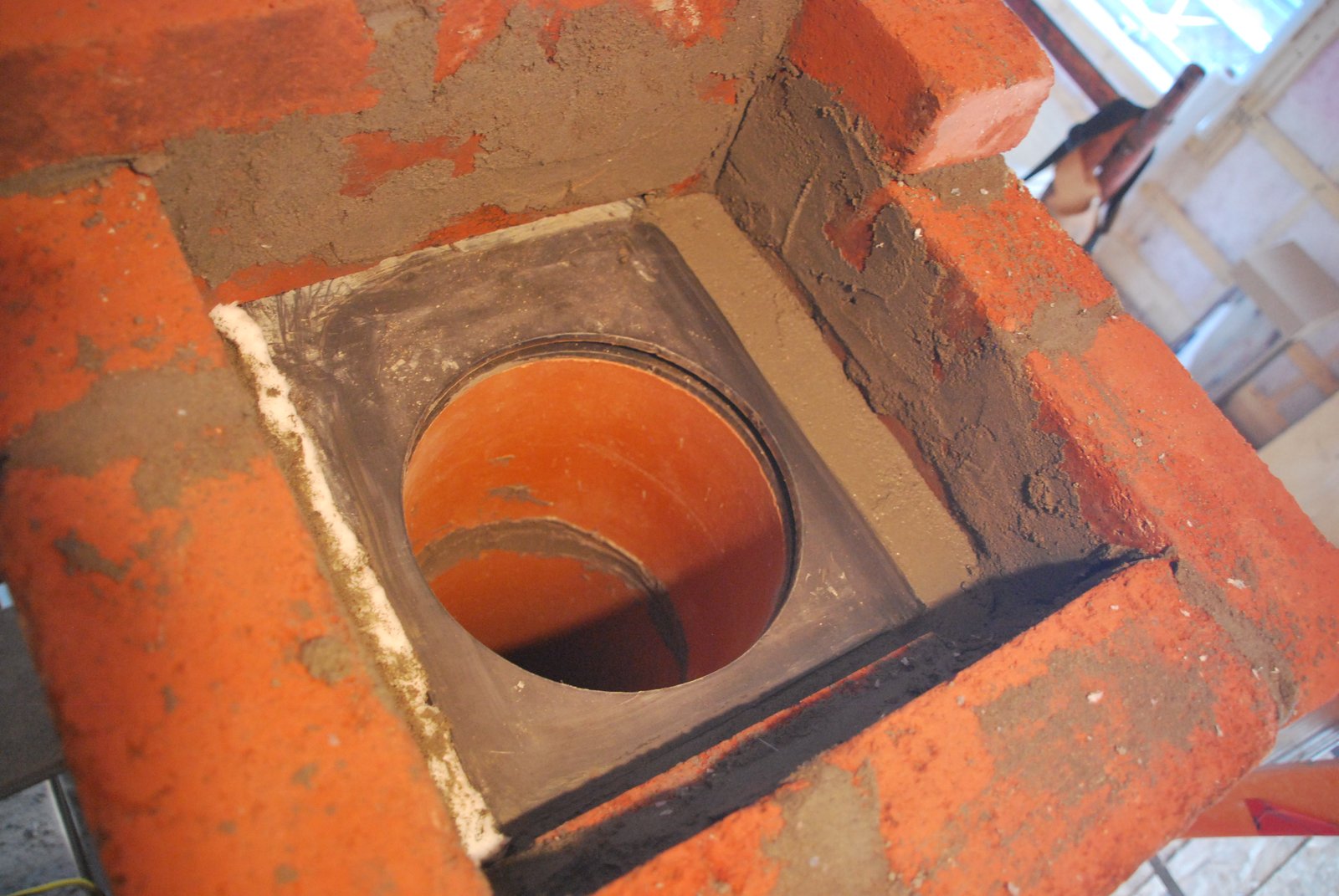
The last tile before the anchor plate is installed, cut level with the last course of the facing.
Triangular pieces of brick have been layed into the concrete back fill of this course to allow the screws that secure the anchor plate, to be tapped into clay brick and not concrete.
The backfill around this flue tile is inserted with care once the tile is in position. The concrete fill cannot be pored 2 courses at a time, as the facing has to be layed to just below the top of the flue tile, and then the tile marked and cut back to exactly the level of the top of the last course.
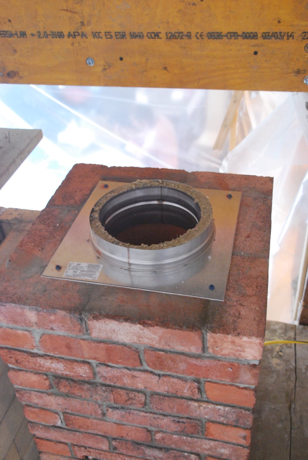
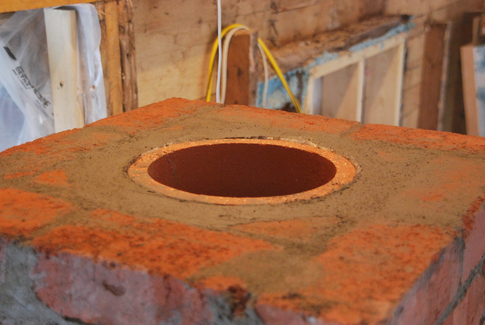
The anchor plate is installed with 4 tap-cons. A ceramic paper gasket is placed between the anchor plate and the masonry.
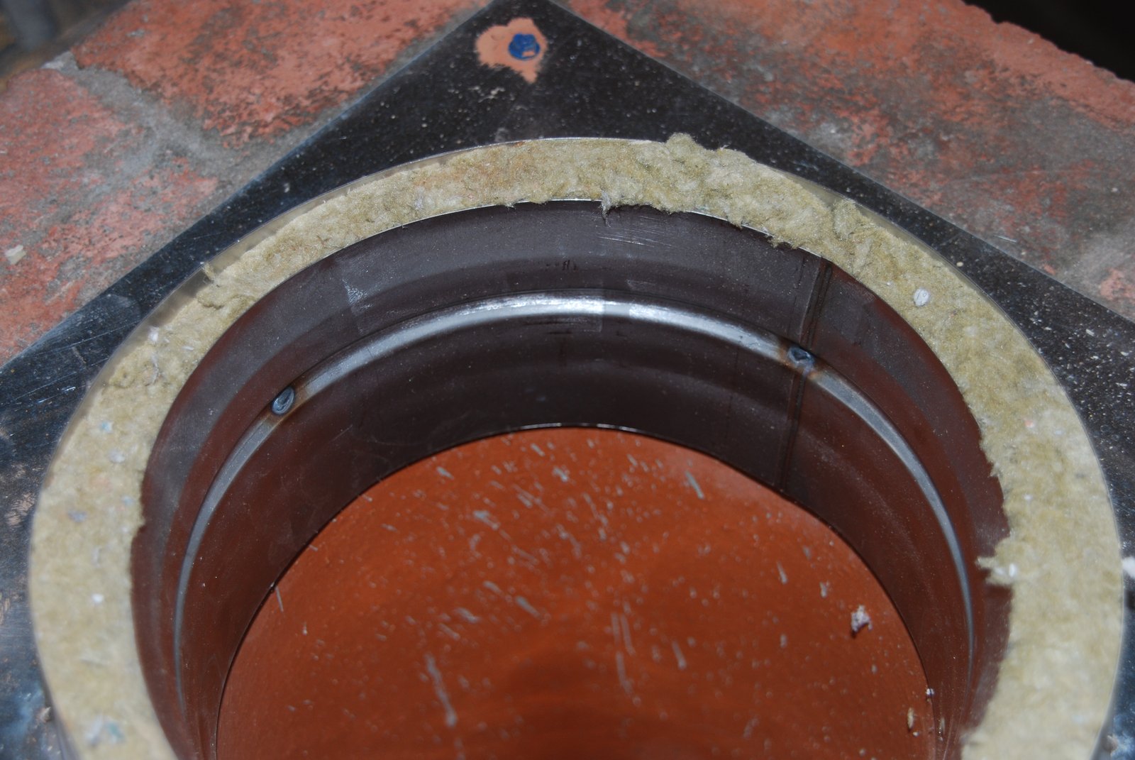
Note that the lower flange of the anchor plate is not absolutely tight in the clay tile. There is about an 1/8th of an inch play between the two (8 inch flue tiles are not all exactly the same diameter). The lower flange of the anchor plate will not fit into many of them, and so the anchor plate has to be taken to the brick yard, and several tiles tried. If no slightly over sized tiles were available, some weight could be ground off the inside of the tile to accommodate the flange, though it is nice to not have to do this.
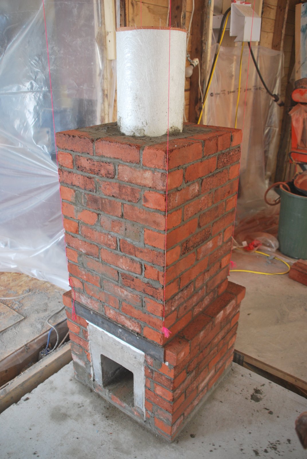
The finished chimney and first course of the refractory core.
The core was built first and then the chimney connection built at the same time as the side channel.
The core was built first and then the chimney connection built at the same time as the side channel.
The open side manifold before construction of the connection and side channel walls.
The connection is gasketed from the rear manifold wall, and the connector with ceramic paper.
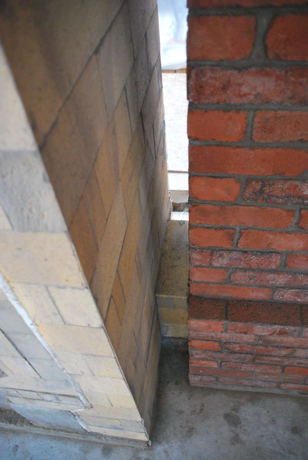
The intersection of the connection and the side channel wall.
Both the connection and the side channel are bridged. The opening in the channel is 8 inches wide, allowing only 0.5 of an inch contact between the connection walls and the ends of the fire brick that cross them.
Detail.
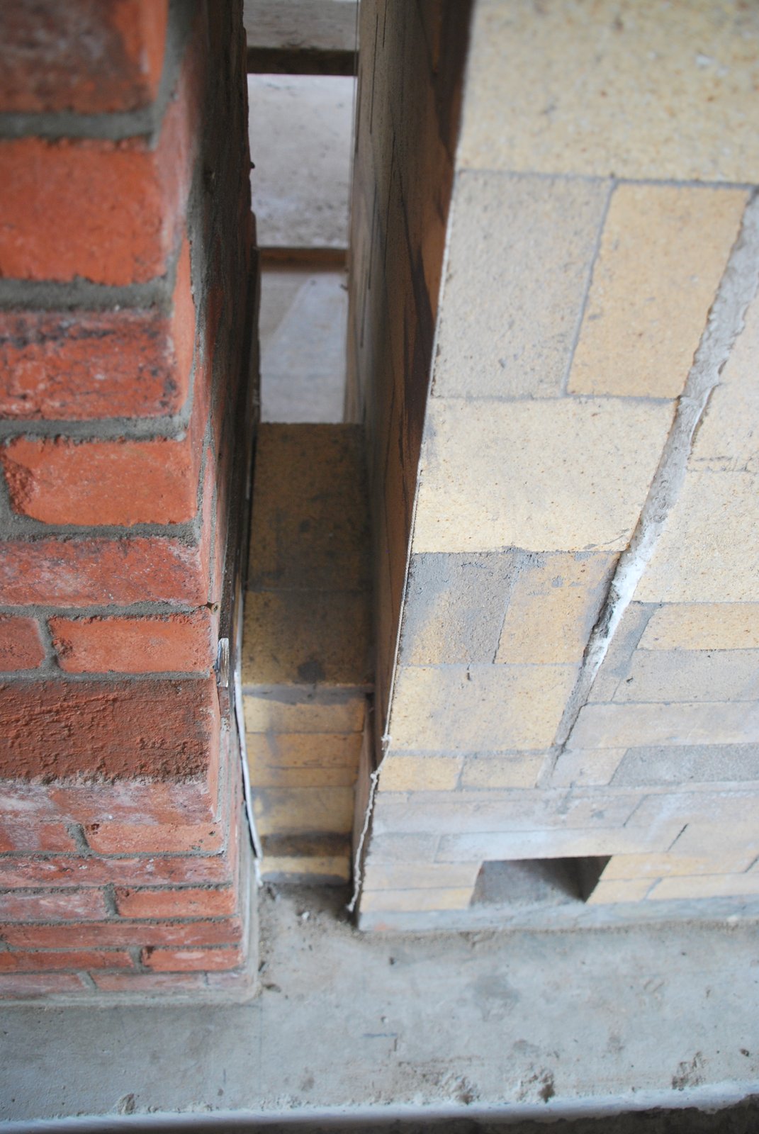
The side channel. Note the angled brick that touches the wool gasket at the bottom right of the image. This avoids an acute angle as the 2.5 inch wall of the side channel meets the 4.5 inch rear manifold wall. As this point is just above the chimney connection, turbulence kicked up from a sharp intruding corner may be better avoided.
The completed connection, seen from the front of the stove.
The connection seen from the rear of the stove.

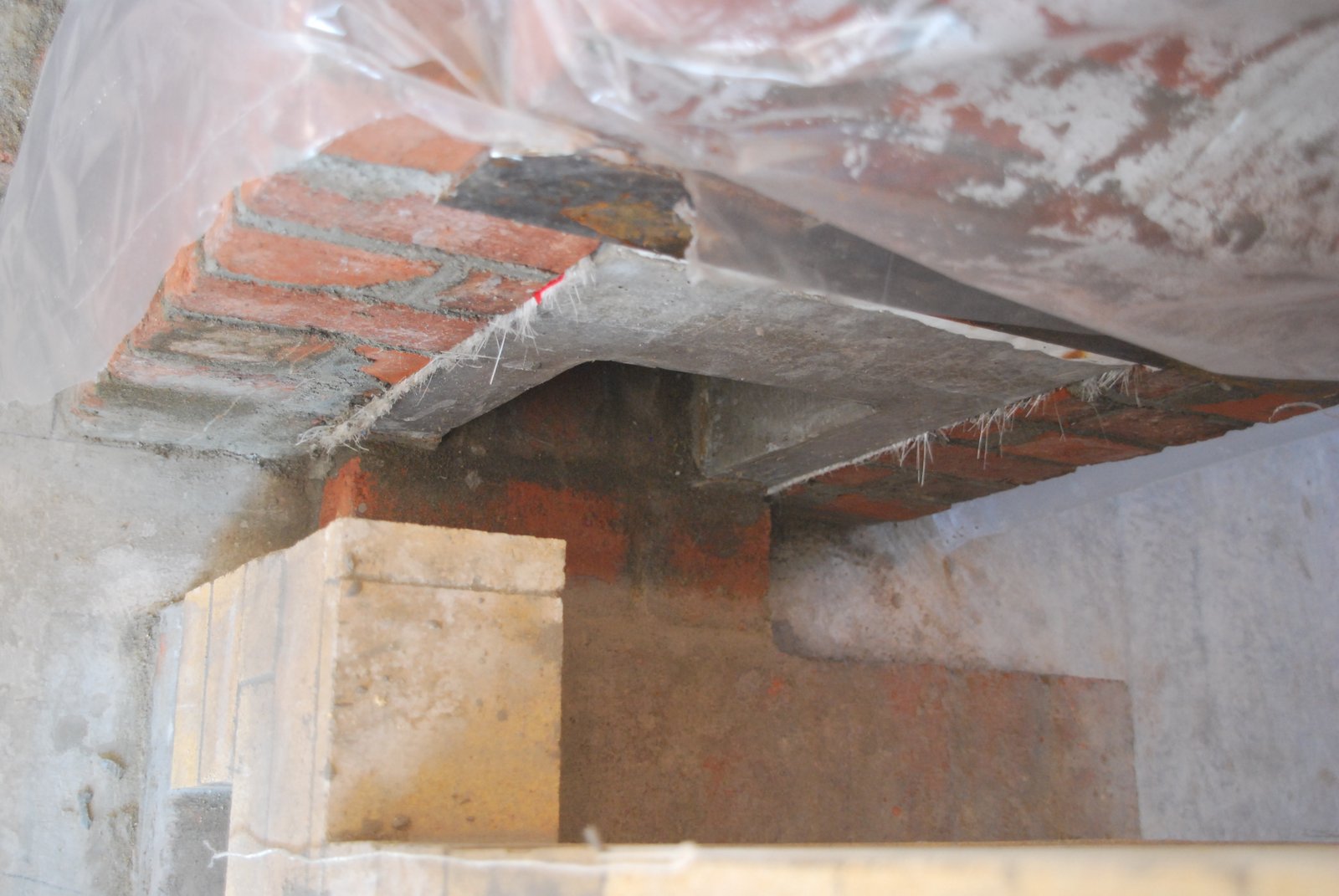
The core and chimney immediately before the installation of the insulated steel chimney.
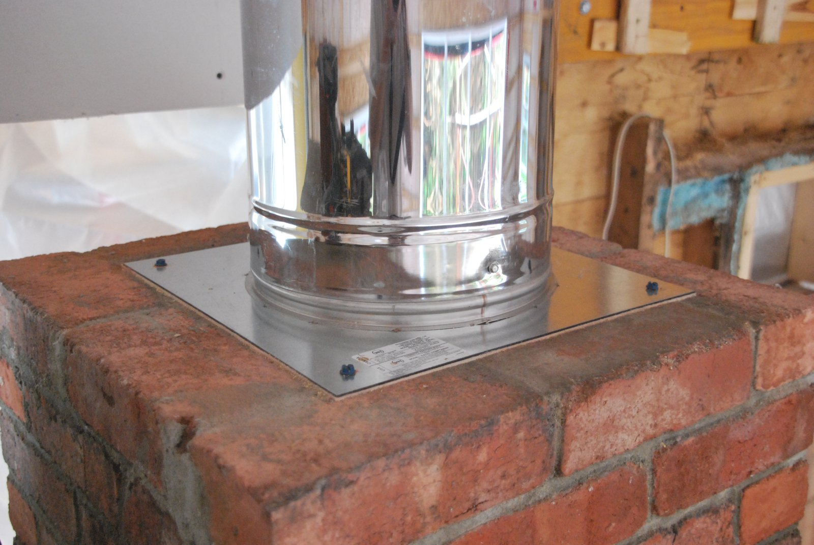
The first section of insulated steel chimney is installed on to the anchor plate.
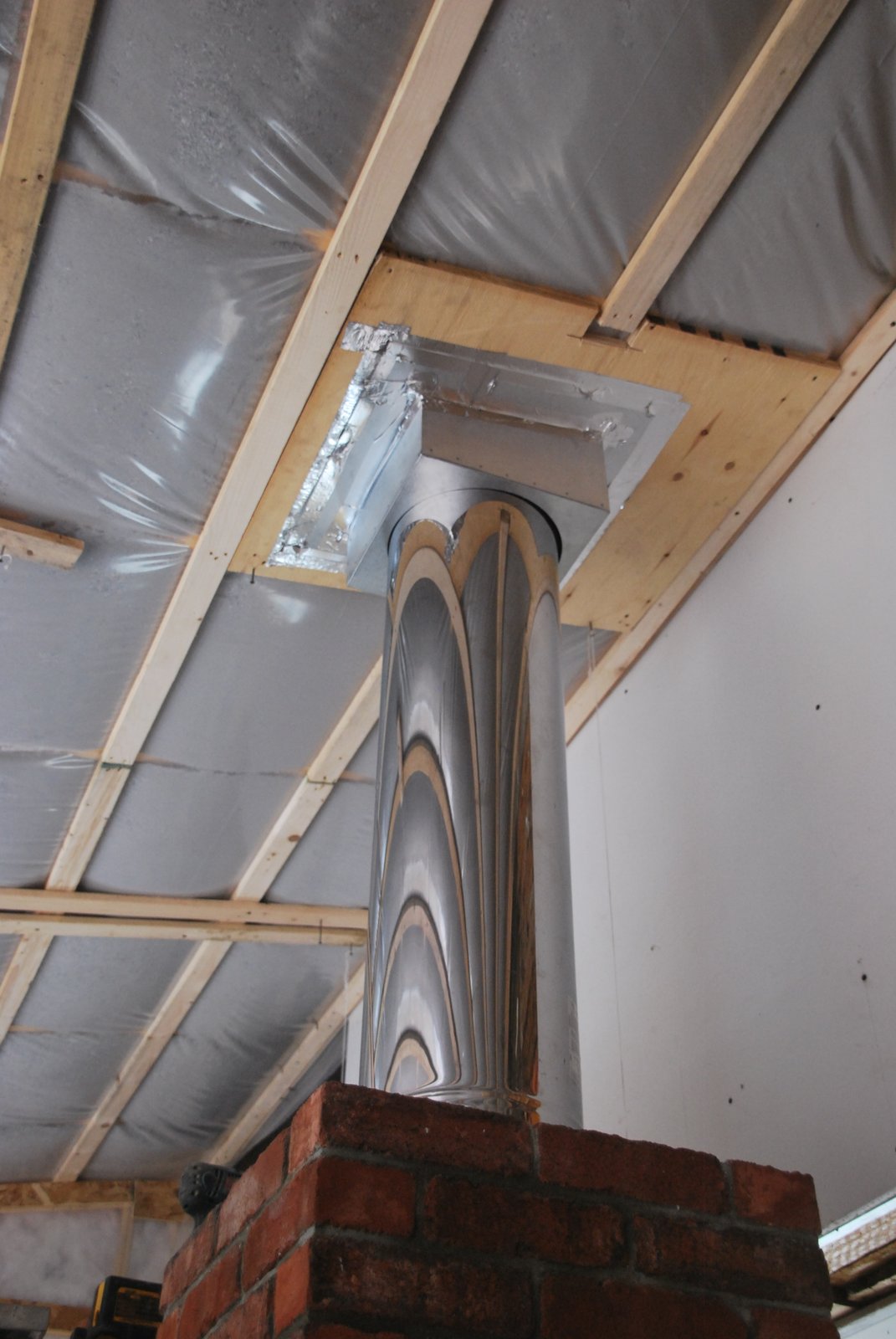
The insulated steel chimney and attic radiation shield. The facing of the chimney was continued up to the sealing in order to cover the portion of steel chimney visible from with in the home. There are though no images available of this process.
Marcus Flynn
2015
