These notes detail the construction a contra-flow masonry heater in the Upper Reaches of The Yarra Valley, Victoria, Australia.
Specific points covered are: Refractory Brick Format, and connection of the core to a single skin stainless chimney flue.
Before contact, and dispossession, this region was occupied by The Wurundjeri Mob.
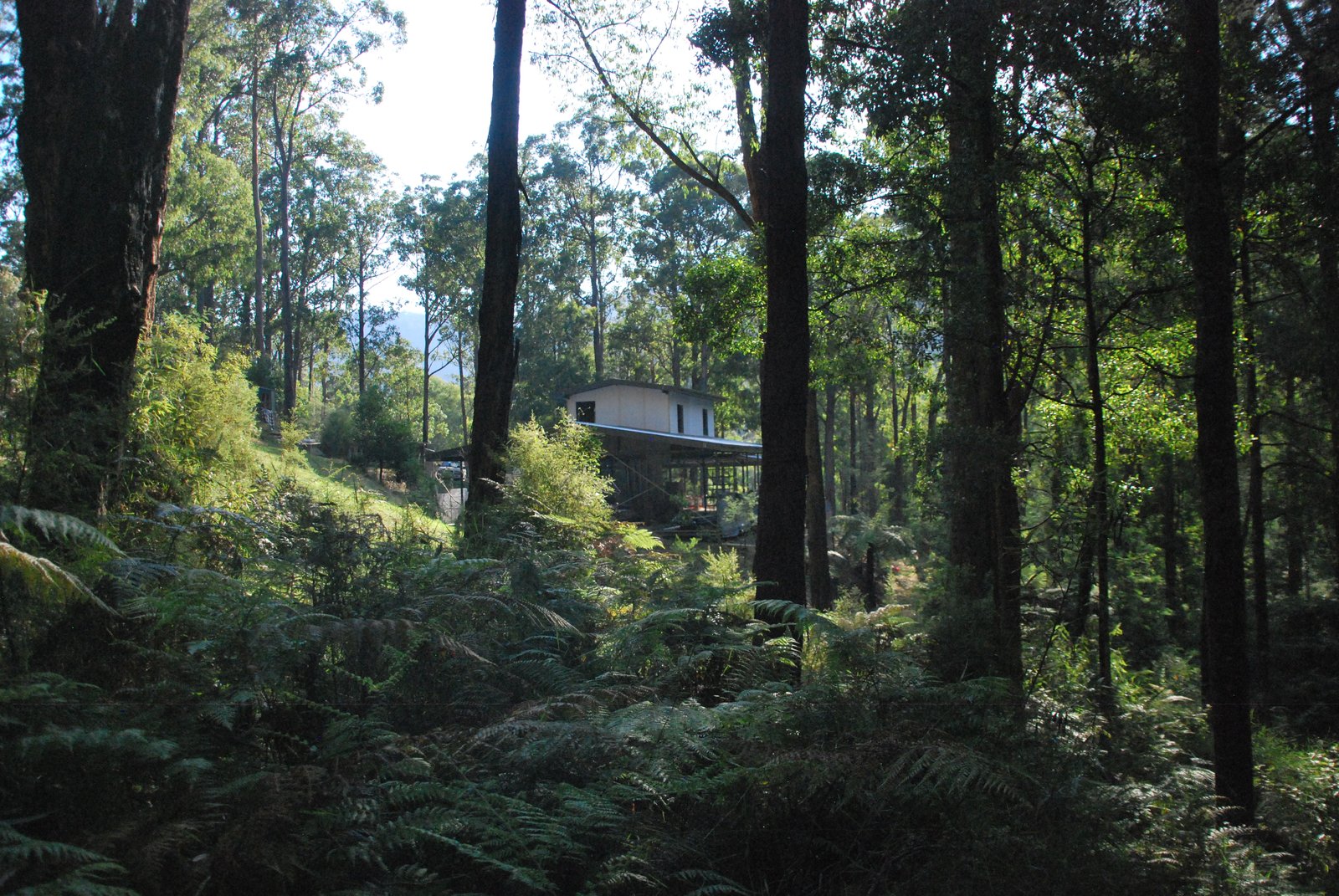
The site: Steel frame and straw bail.
Materials:
Refractory Brick
Shiragawa: Shiral 38X (
TDS 
)
Refractory Mortar
Shiragawa: Shirabond 50 (
TDS )
Castable Refractory Concrete
Shiragawa: Shiracast 160 AR (
TDS )
Ceramic wool
Superwool 607 HT: 13mm thick Specific Density 128 kg/m
3 (
TDS )
Fibreglass
450g Chopped Strand Matt
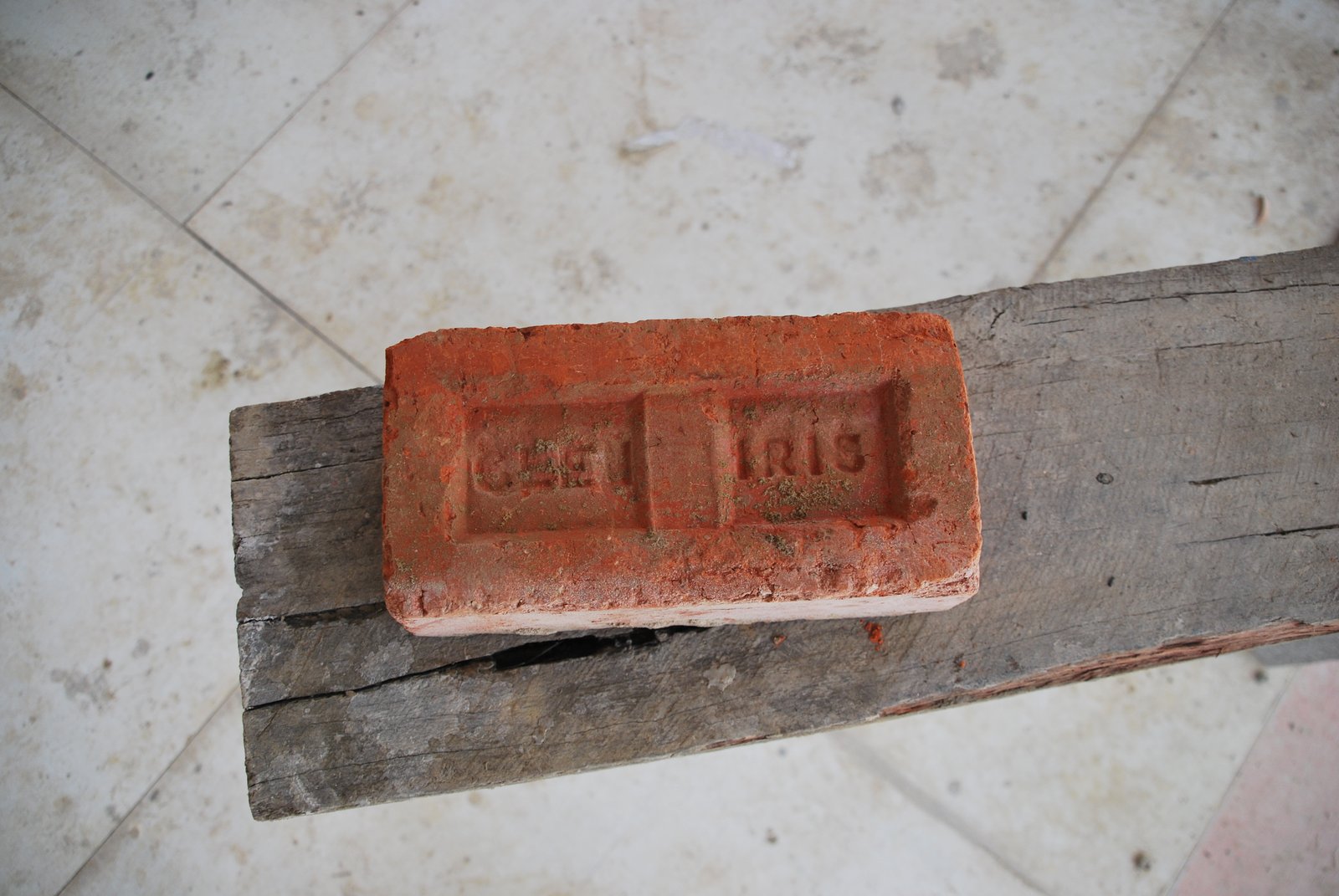
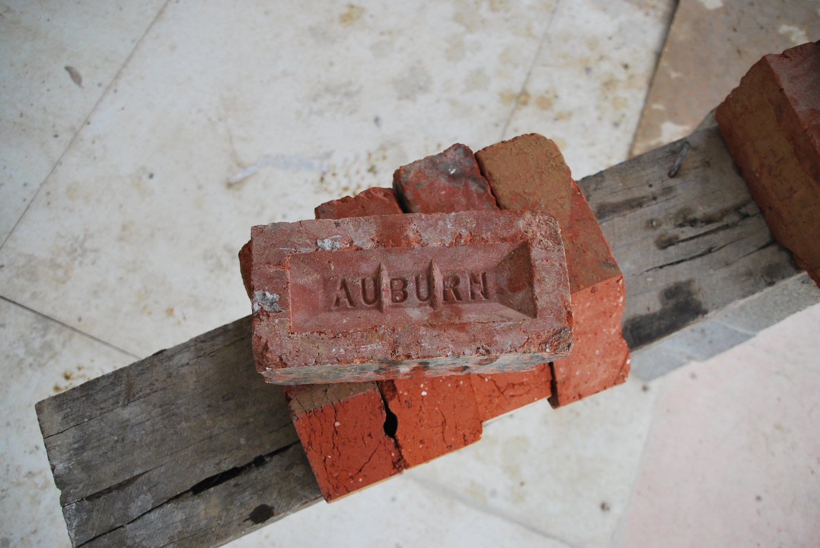
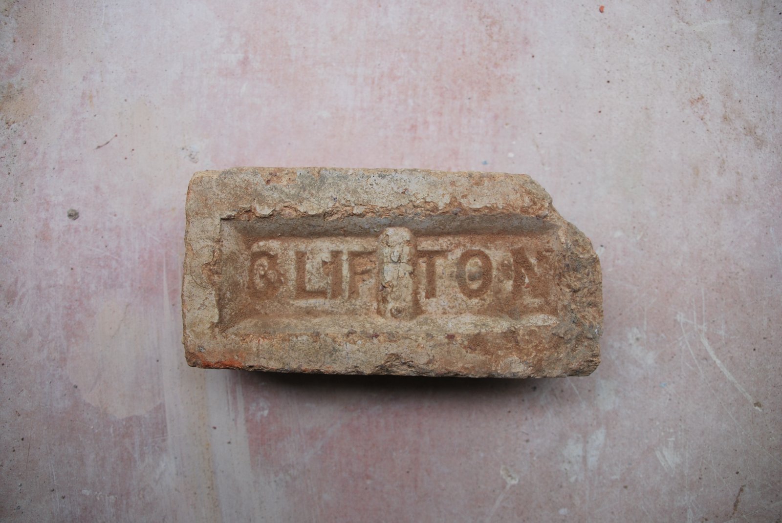
Facing Brick
Local Recycled.
Steel Chimney Flue
Spiro Duct .095 gauge Custom made ‘T’ in .095 mm
The Refractory brick available locally were either 5 cm or or 75 mm thick as opposed to ‘International Format’ at 64 mm thick.
Equal portions of each were ordered. The intention being to use the 75 mm in the fire box every where except the liner. The 50 mm for the side channels and liner. And the remaining brick of both formats, in areas where lift per course, or wall thickness were of no relevance.
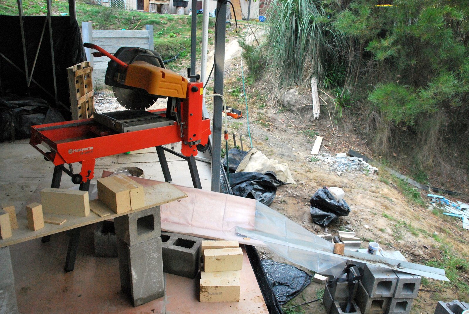
The Huskevana 400 F 400 mm saw. Actually less versatile ( for this application) than the 350 mm 350 TSE. The water feed set up providing the saw with only clean water from a hose rather than water recycled from a reservoir by pump is impractical in regions with limited amounts of water. Or where the stream of waste water cannot be easily evacuated from the site. The 16 inch blade makes, rolling the work (on the table) under the blade, to align the mark with the blade, impossible.
The foundation slab of the stove and chimney had, due to the superstructure of the buildings floor, to be poured above finished floor level.
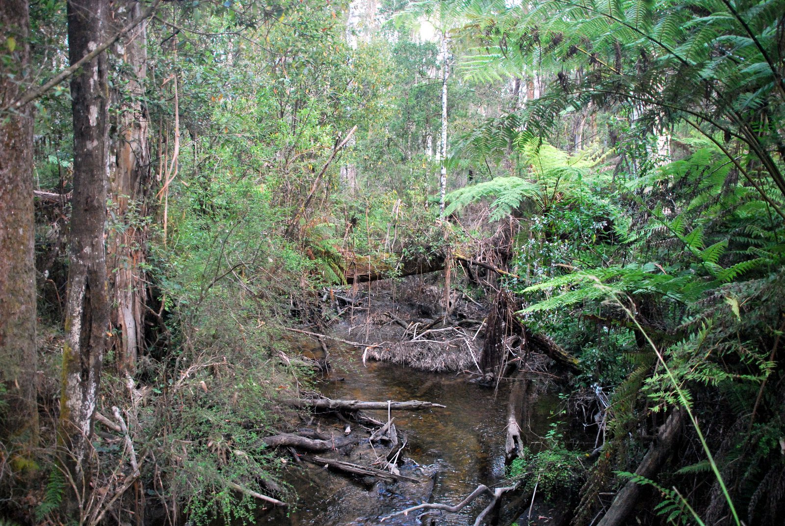
The ideal site: perfect cross ventilation, complete shade, and abundant light.
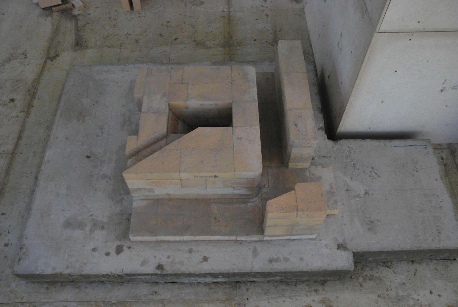
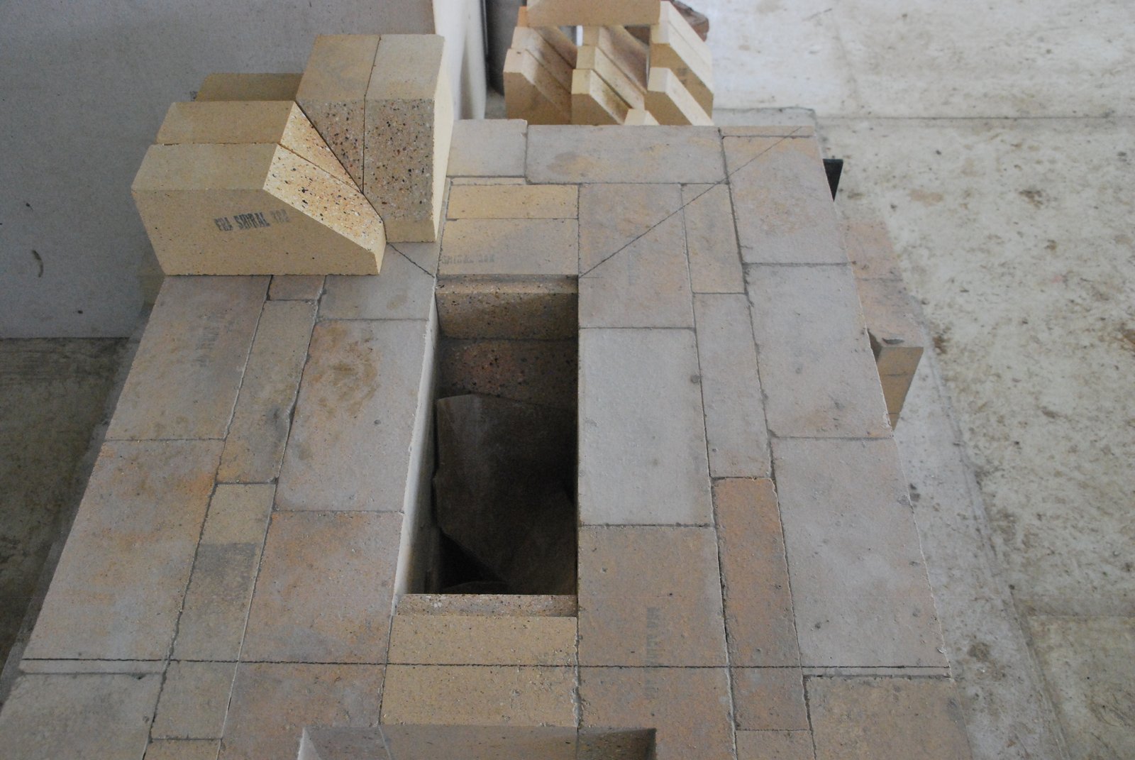
The initial courses of the core showing the ash drop into the foundation, and the supplementary under air intake channel.
The mark out for the rear corners of the firebox walls. The horizontal pencil line across the front forms a square with the rear of the fire box floor. The two diagonal lines corner to corner will indicate the line of the cut through the compound corner.
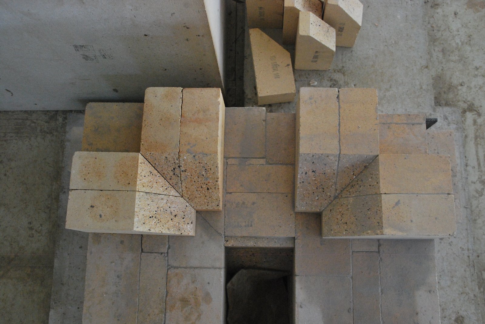
The corner set up, with the right corner in place and the left layed dry.
The corners of the firebox wall are gasketed with cardboard cut from the box of the ceramic blanket, or hardware.
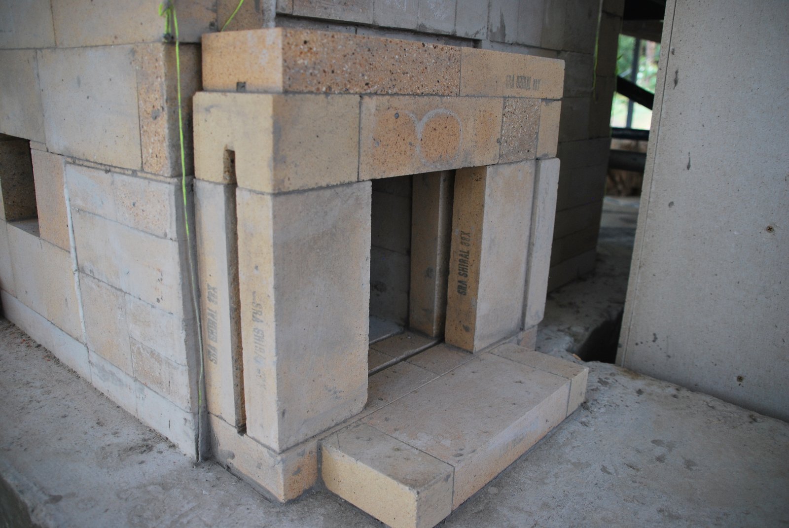
When working in international format the firebox walls would be composed of two wythes of 64 mm shiners. Here the outer wythe is layed in 75 mm and the inner wythin 50 mm brick. This gives a wall of 130 mm, i.e. the same size as if built in international format, but slightly more stable, as the outer, permanent, wythe is 75 mm and not 64 mm thick.
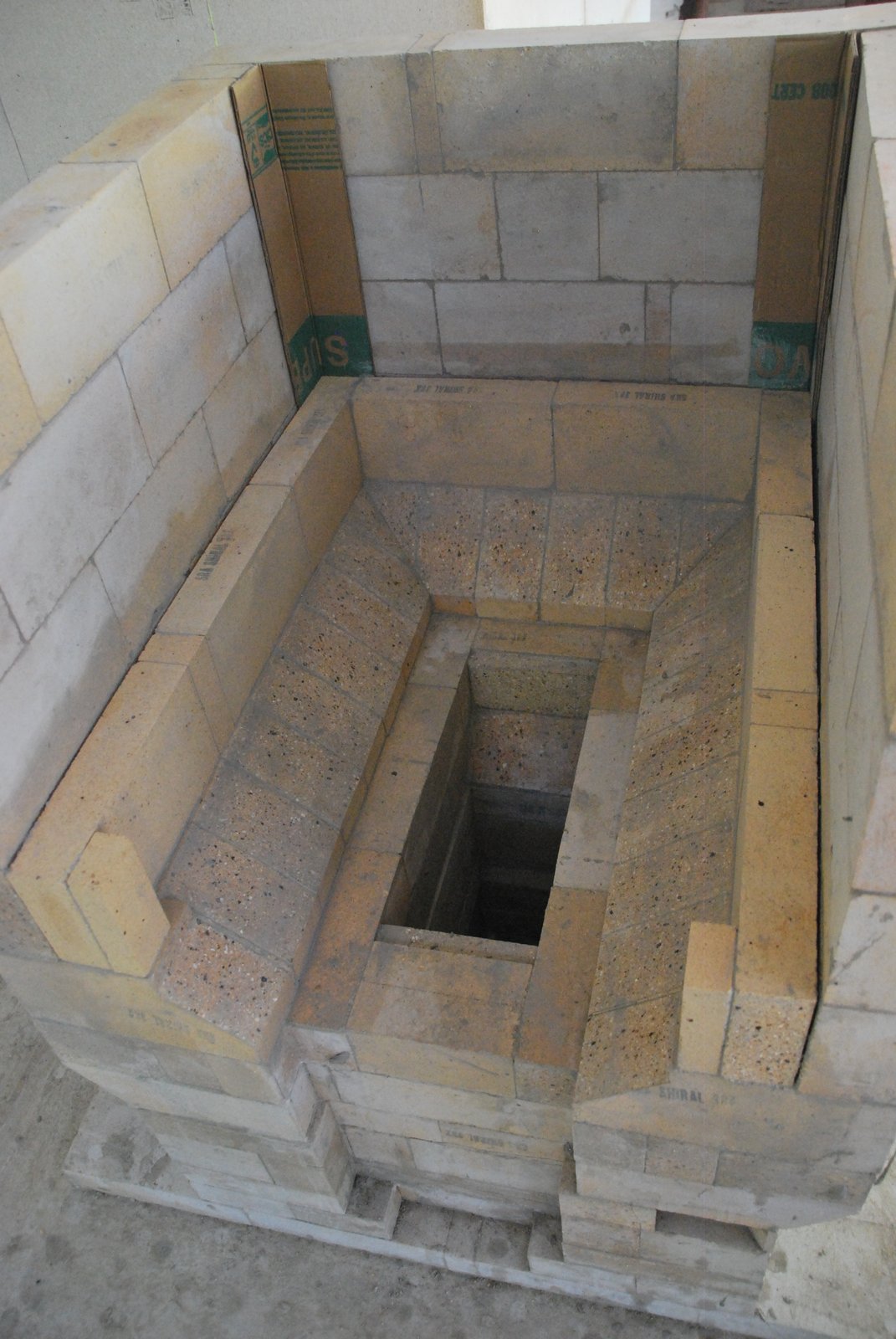
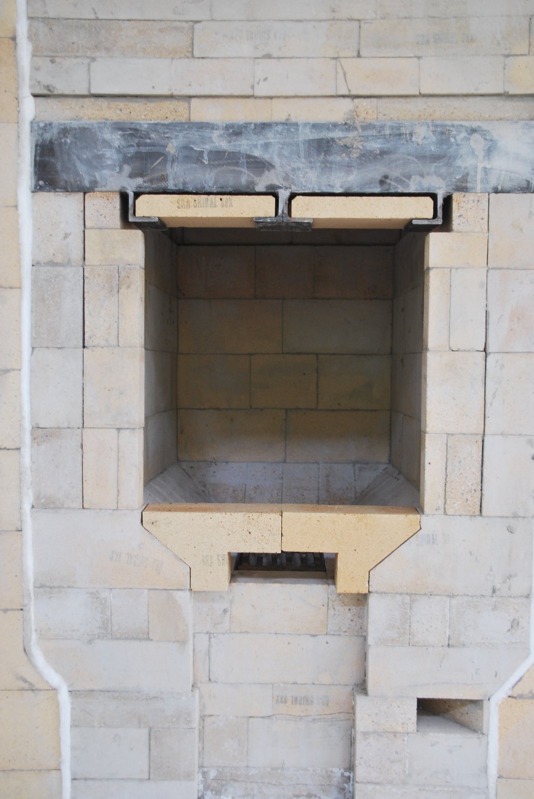
The fire box. With heat shields and primary air deflectors.
Final set up of the fire box loading opening.
The frame of the guillotine damper, is layed against, and not tied into the rear manifold. As a single skin steel flue liner will be used the only viable place to install a damper is in the connection between the stove and its chimney. This in its self is not a complicated procedure. What is of great importance though is that the damper be robust and withstand being operated on a daily basis. The space between the heater and chimney available to build the damper is limited to the width of the chimneys wall , plus the stoves facing, i.e. approx 23 cm In order to allow more room in the adjacent direction the first 6 courses of the facing would be expanded on three sides, and then corbel back over 3 courses to the final dimensions of the chimney.
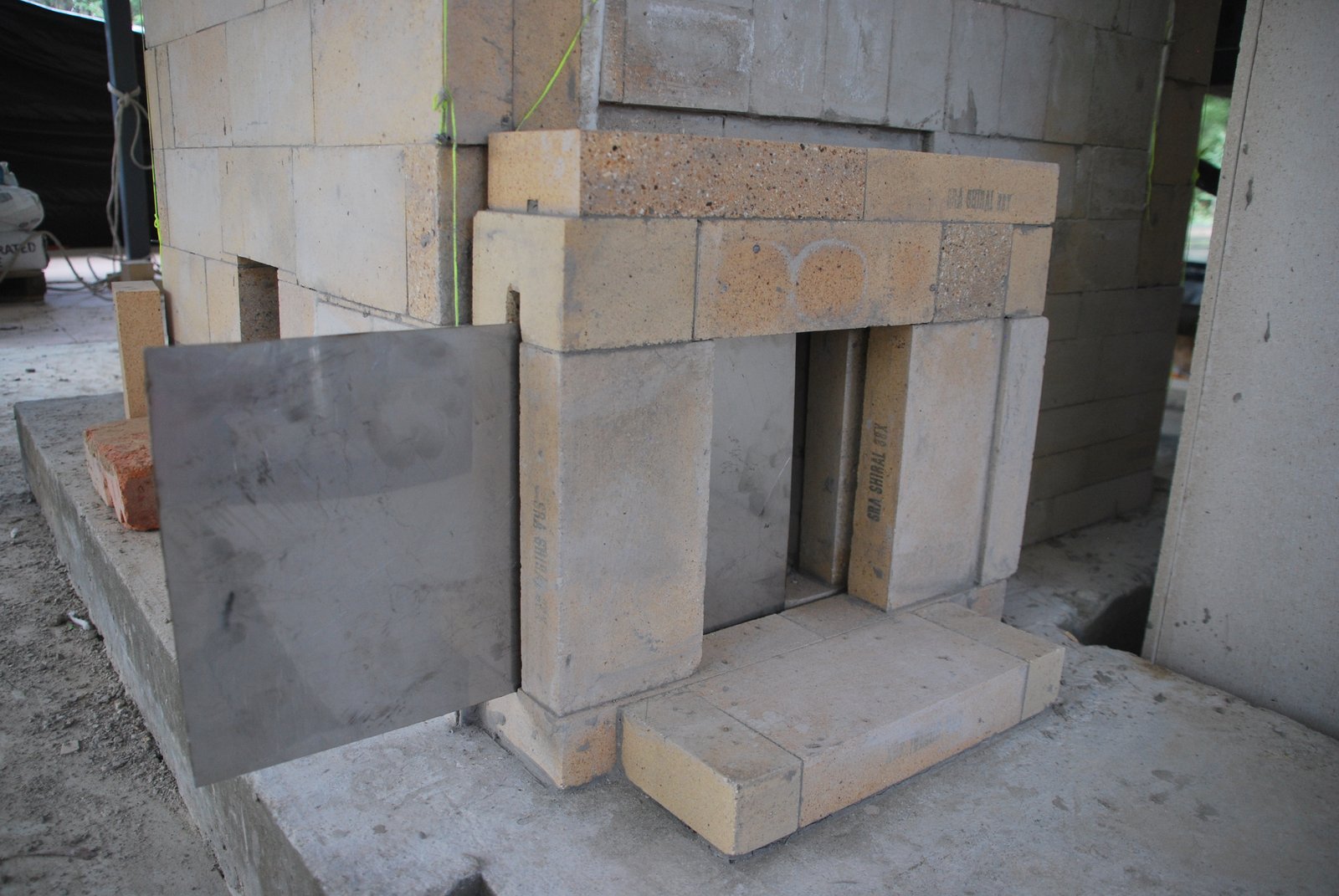
A stainless steel plate is used to assure the rebate within the frame is free of obstructions.
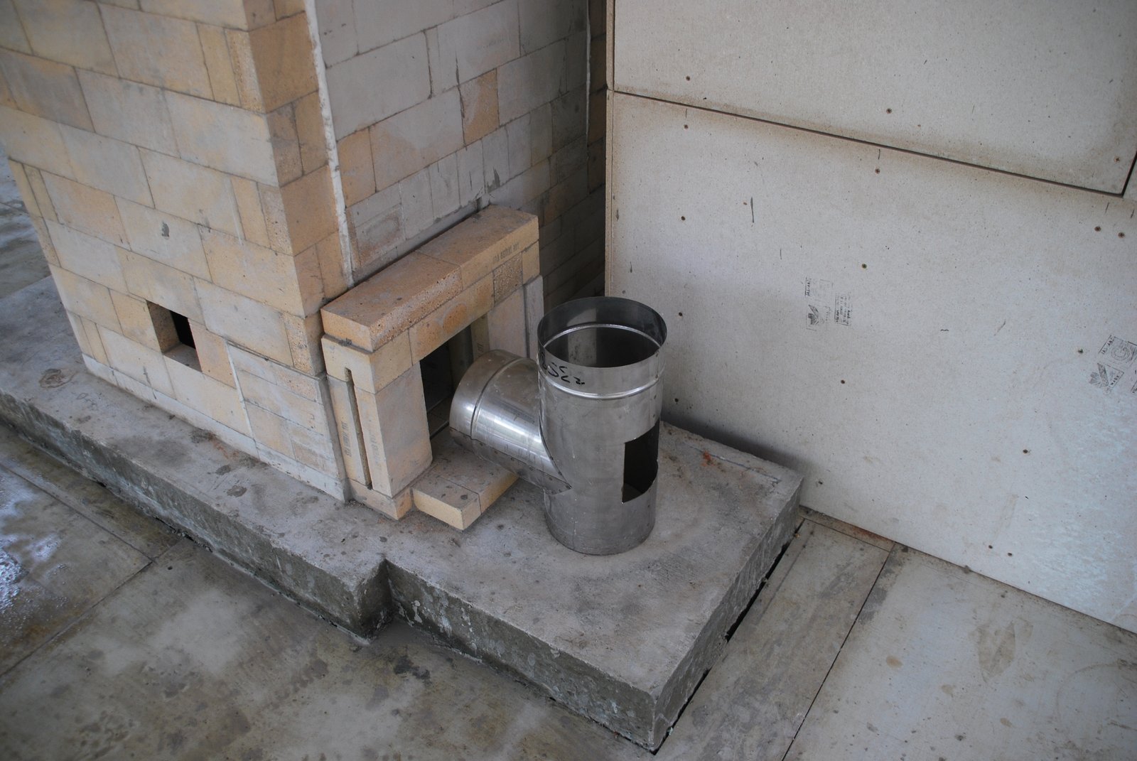
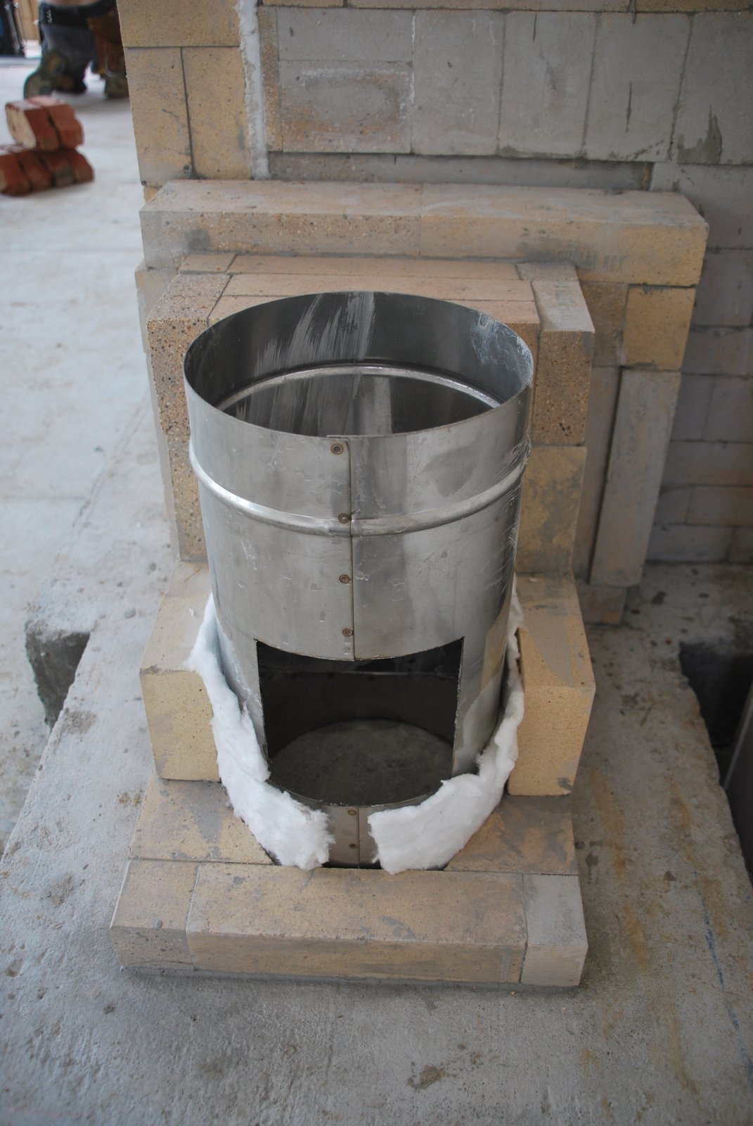
0.95 gauge stainless steel ‘T' section is lined up in its final position. The access opening opposite the connection was cut out with a grinder.
Two brick are cut to the curve of the flue. Seen here layed dry.
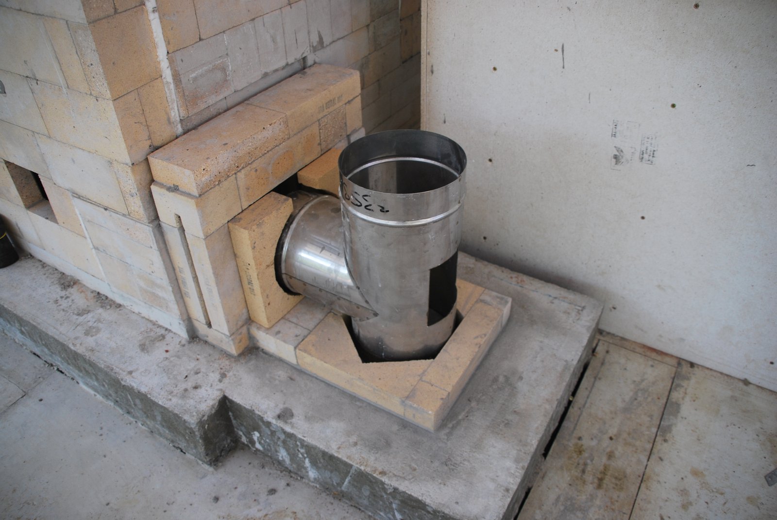
The horizontal portion of the ‘T’ piece is gasketed and the brick layed around it. These brick close the connection, i.e. surround the open end of the ‘T’ And help stabilize the damper frame.
Two more courses of shiners are layed over the connection.
Note the extension of the vertical potion of the ‘T’ piece that protrudes below the level of the horizontal connection. This allows any condensation from the upper portions of the chimney to drip down into base of the chimney and be confined within the steel flue, rather than run into, or, around the damper frame. As the flue consists of an uninsulated single skin, and the damper frame layed in water soluble HTC, condensation dripping down the chimney could be an issue.
Note: The soaper and two soaper pins, that form the first course of refractory brick below the access opening in the flue, were removed before the facing was started.
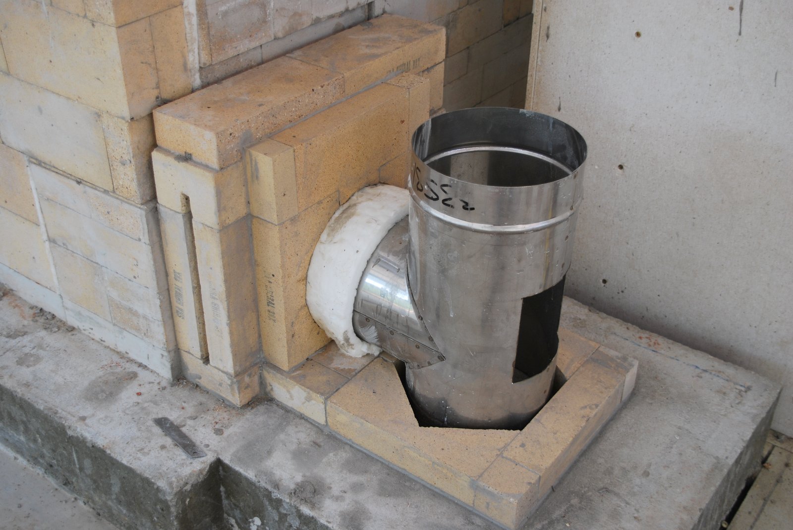
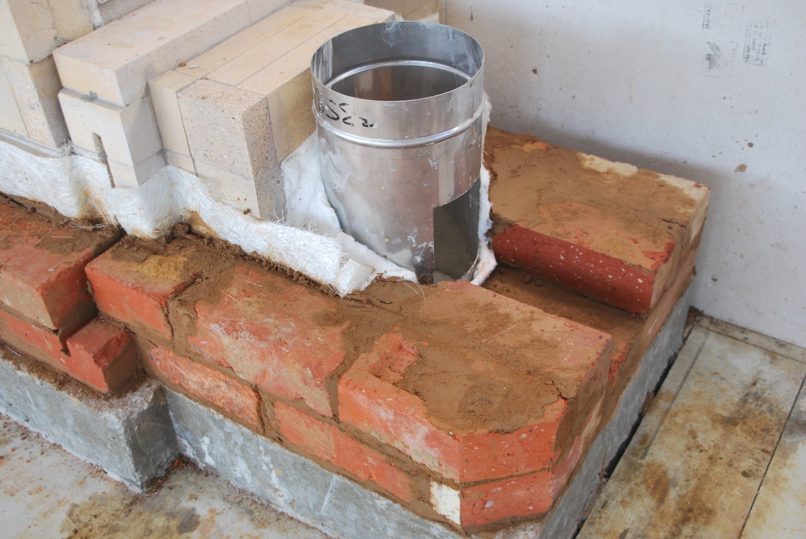
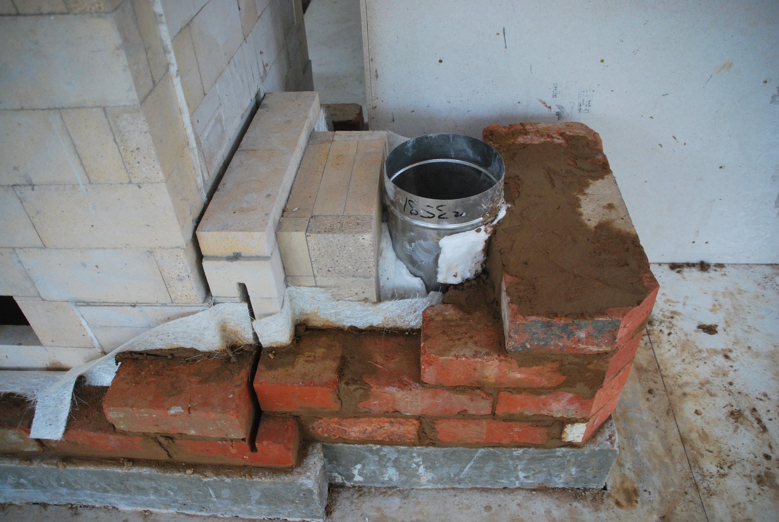
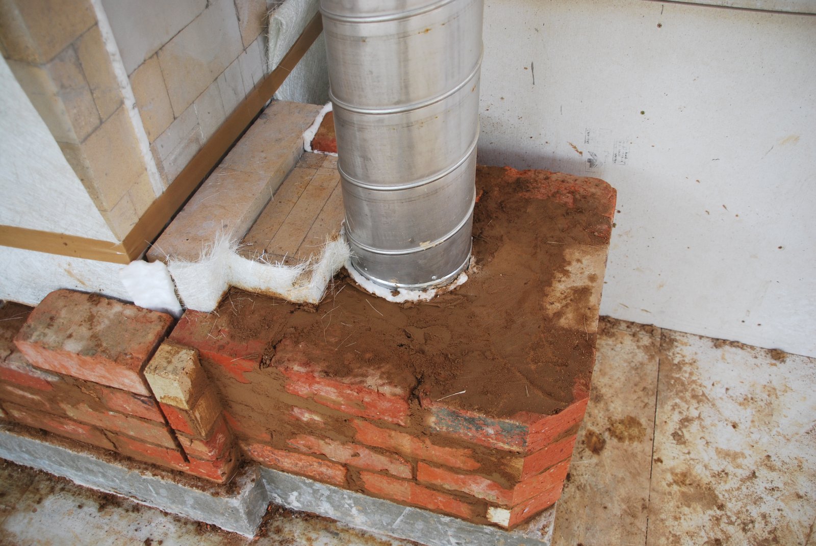
The first courses of clay brick around the connection. The Steel flue is gasketed with wool and the masonry of the damper plate and the connection with two layers of 450 gram chopped strand mat.
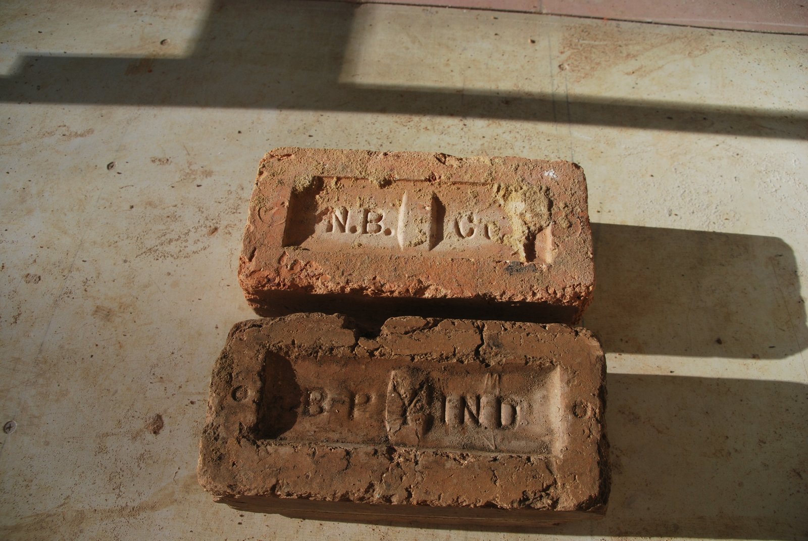
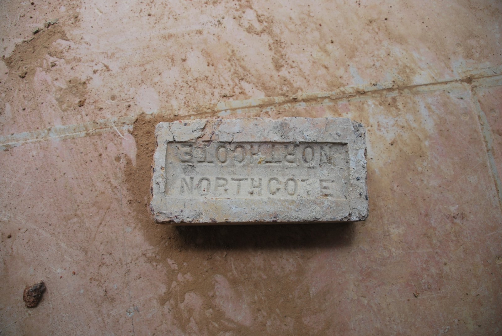
Recycled brick made and layed in the Melbourne area during the 19th century. These brick are extremely dense and do not cut easily. As the facing will be rendered uniformity of colour of texture was unimportant.
The start of the opening through the facing to the damper frame. Due to the opening being only 3 cm from the corner, work in this area has to be precise, with selected brick.
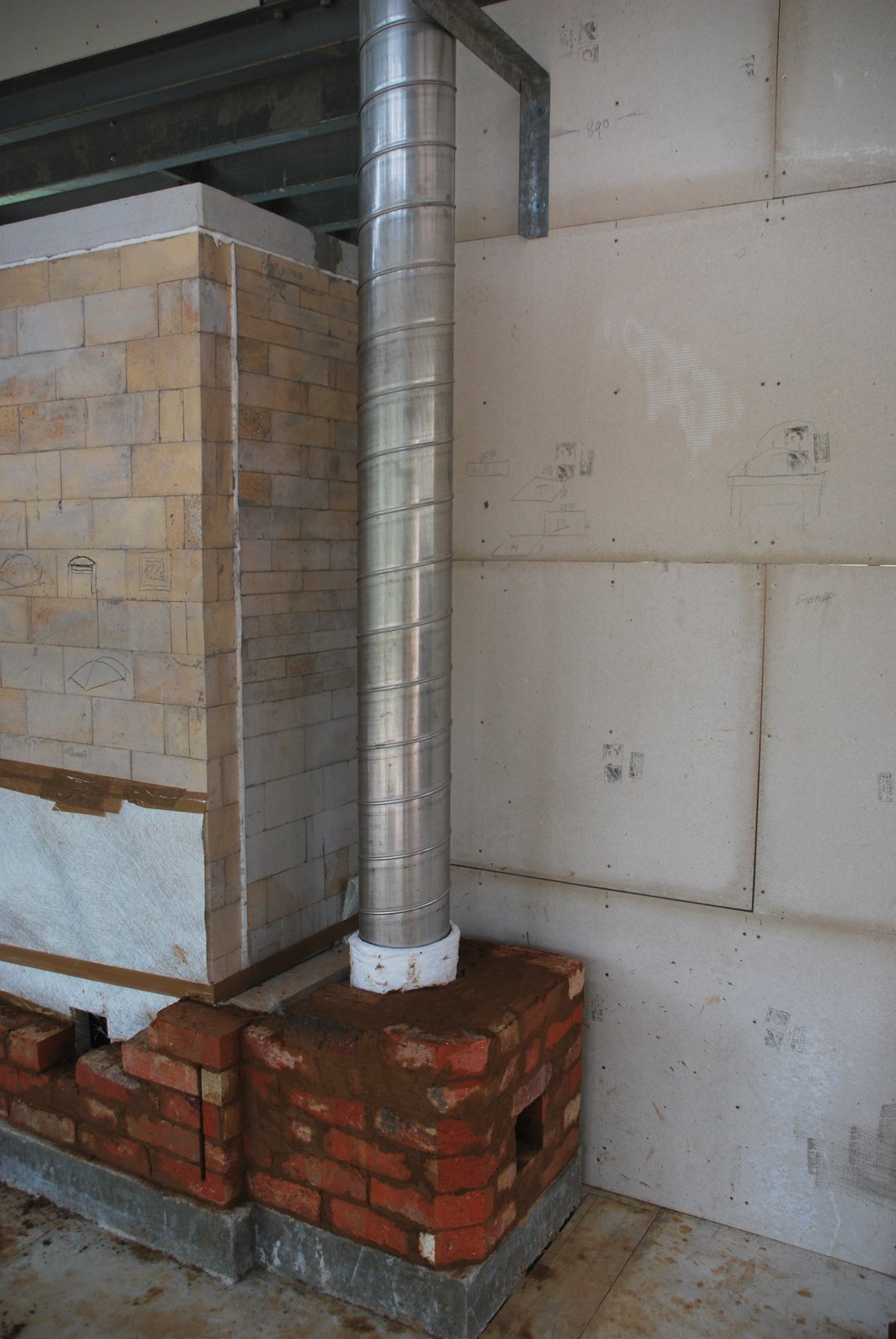
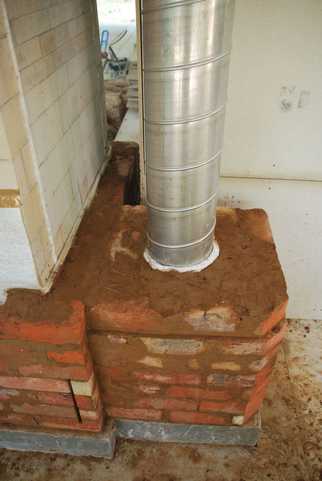
The Stainless Steel flue is attached to the ‘T’ connection, plumbed and held in position with a bracket fixed to the roof.
Spiro Duct flue is available in almost infinite lengths. In this instance one peace runs from the connection to the chimney top.
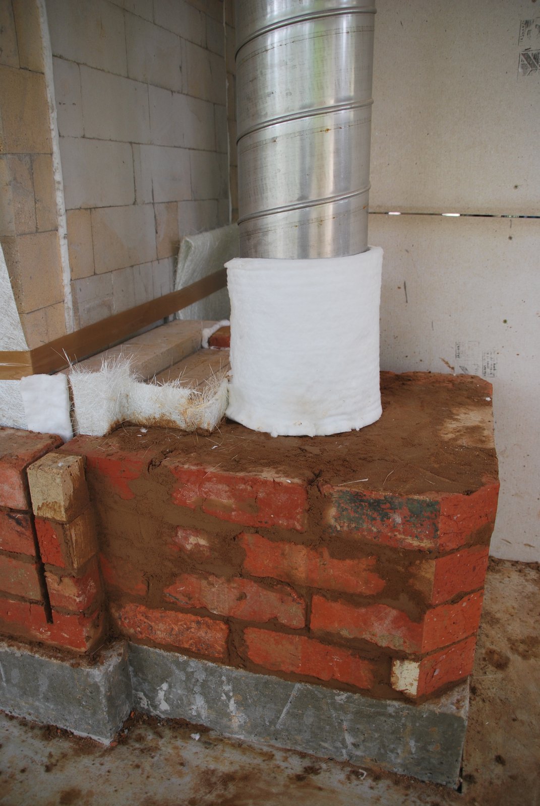
The flue is wrapped in wool which will act as an expansion and smoke gasket, and also insure the flue warms up quickly assisting the draw and reducing condensation.
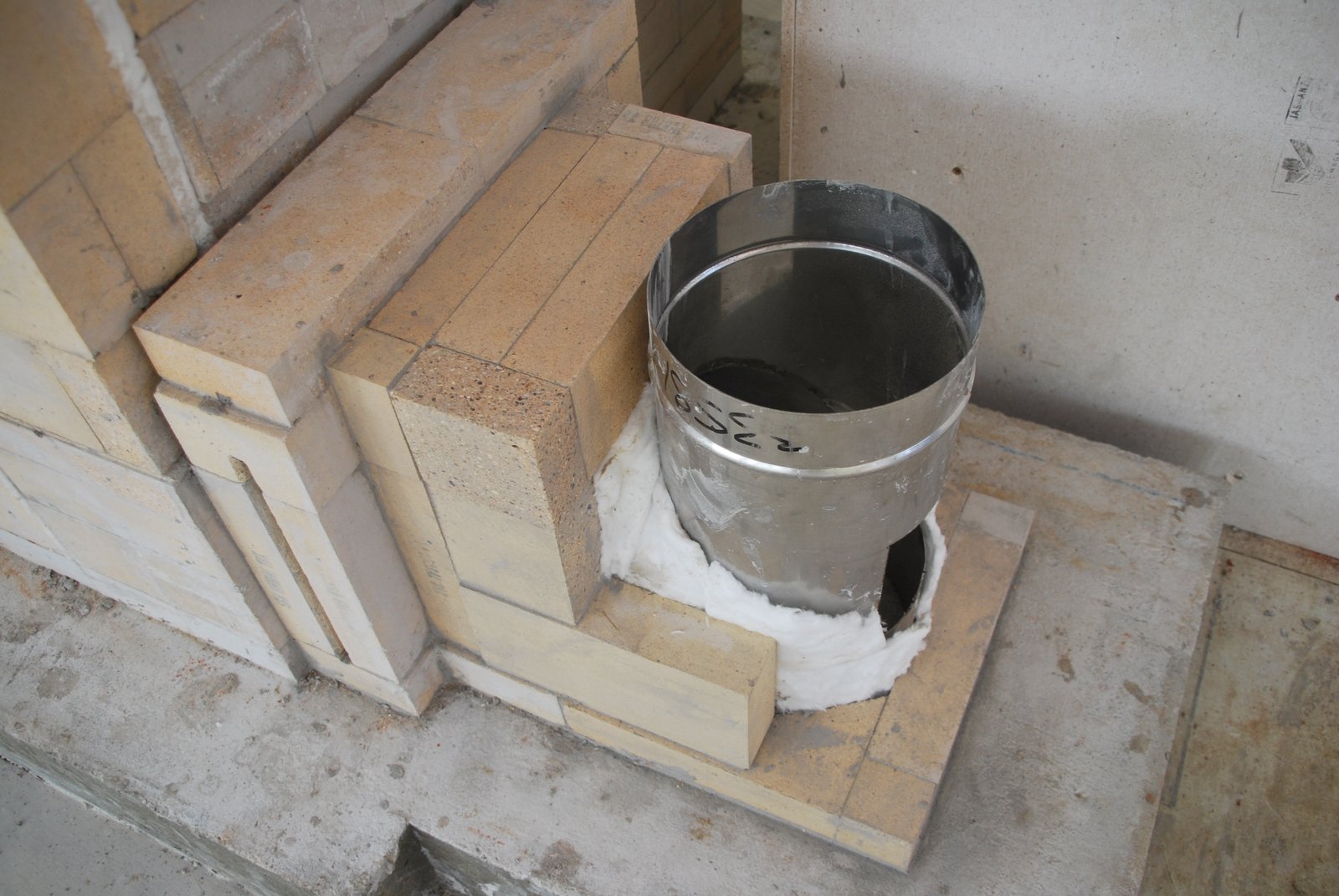
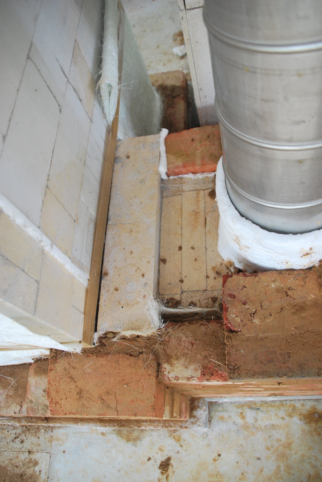
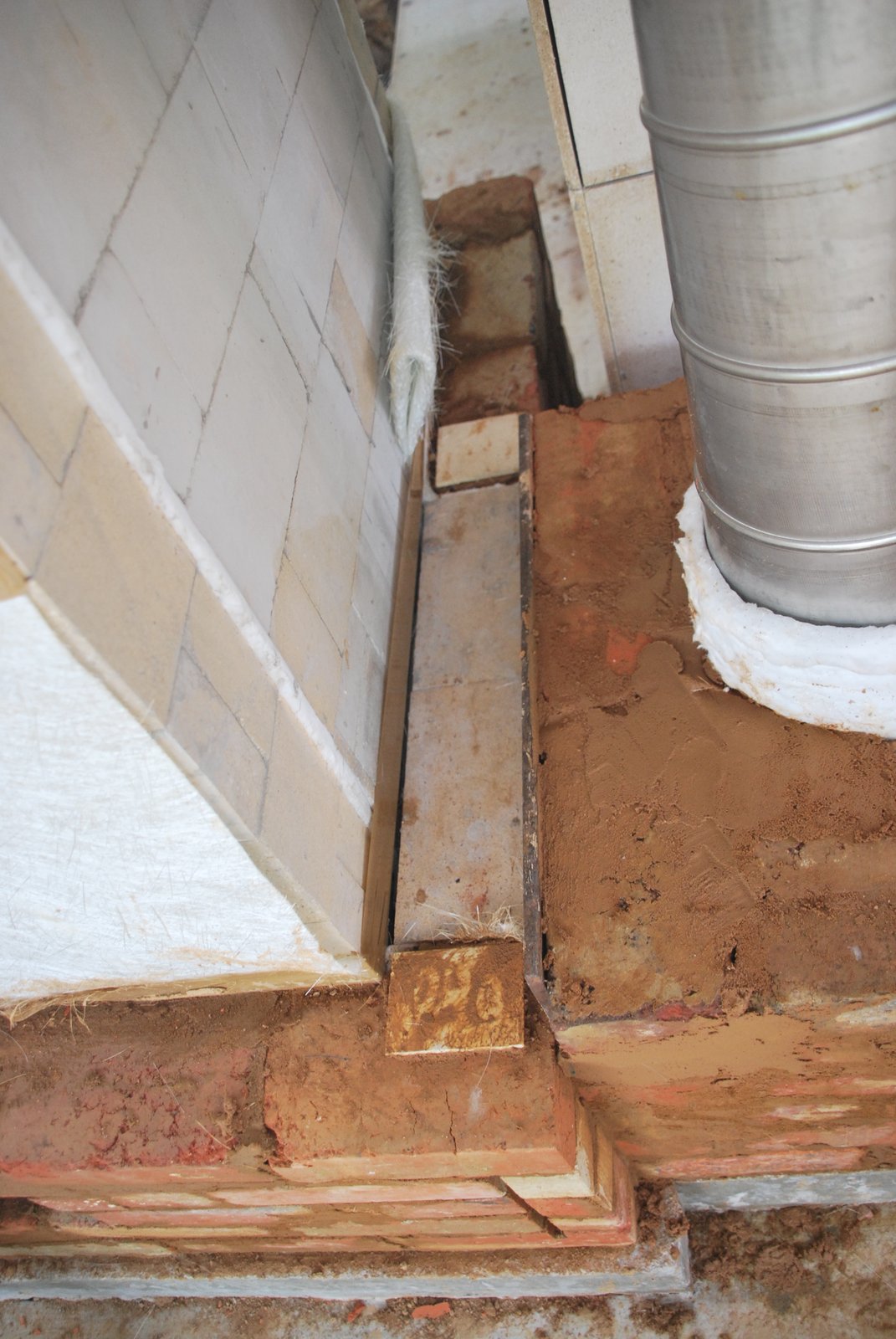
View of the connection from above. The base of the chimney has been surrounded in brick. The facing of the far side of the back of the heater will be layed against the connection, i.e. not be gasketed. This is to back up the damper frame with solid masonry and avoid the damper plate knocking the connection loose if it is pushed in with any force.
The masonry of the connection its self will expand into the inside of the smoke path and the opening that holds the guillotine plate.
Expansion will be almost negligible at the connection, and gasketing maybe not necessary.
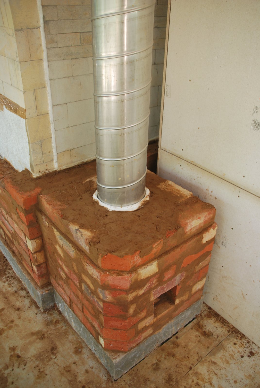
The opening for the damper plate. Installing a damper whose plate when open protrudes at floor level can disrupt foot passage, and operation necessitates bending down. In this situation, with a continuous steel flue there is no option. Advantages of its location are: visual and physical inspection through the chimney and side manifold access openings. Removal of the plate for cleaning. No risk of the frame becoming compressed and causing the plate to bind due to the weight of flue tiles above. Simple construction involving masonry materials. The plate can be cut on site and so there is no need of a blacksmith.
As the frame is masonry and the plate can be easily replaced, there is no question of rusting in the long term
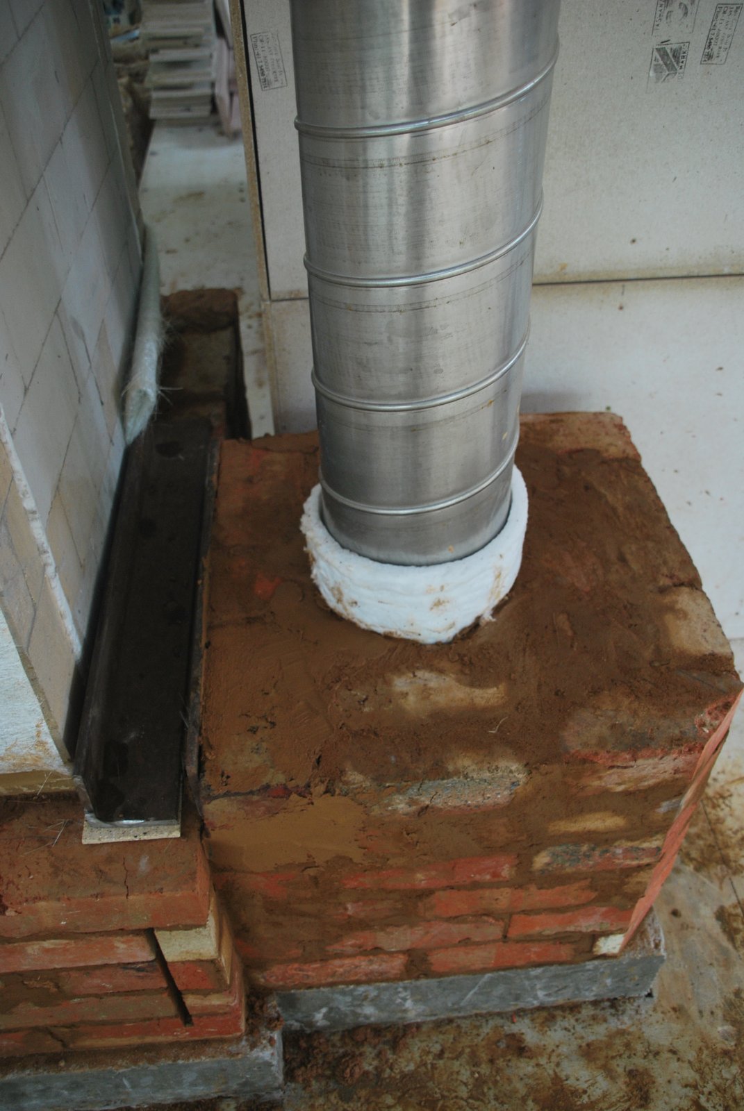
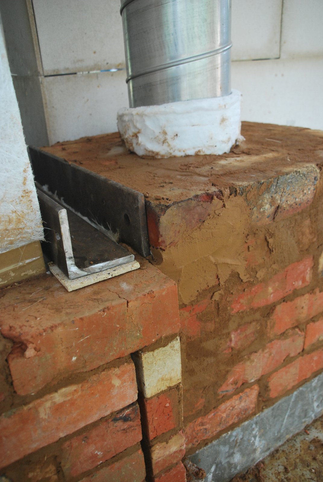
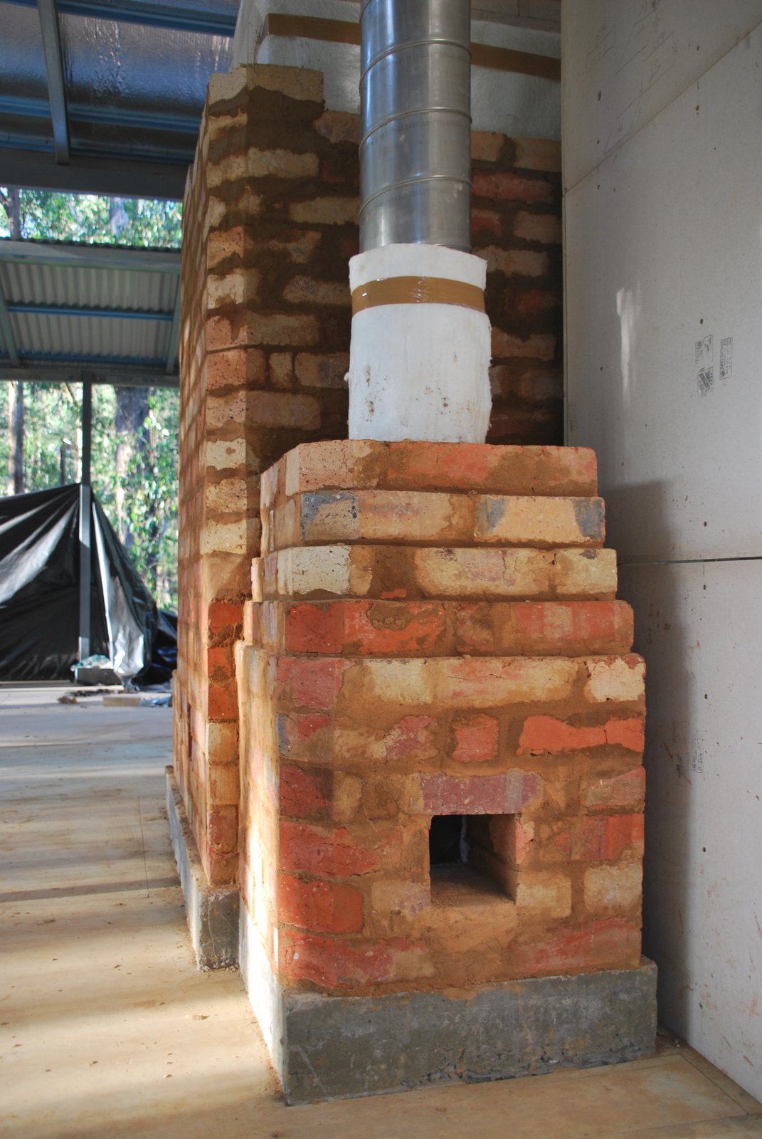
The opening for the connection to the chimney has been bridged by a piece of 100 x 100 x 6 mm angle bar, seen here with one course of brick layed upon it.
The masonry frame of the damper is slightly higher than the masonry surrounding the connection into the chimney to the right. Two thin heels of brick are layed to compensate for this, so that the angle bar lintel does not rest directly upon the damper frame.
The principal of this technique is that the connection, damper, and steel flue, remain entirely free floating within the facing.
The lintel in place. The heaters wall behind the lintel will be gasketed before it is layed.
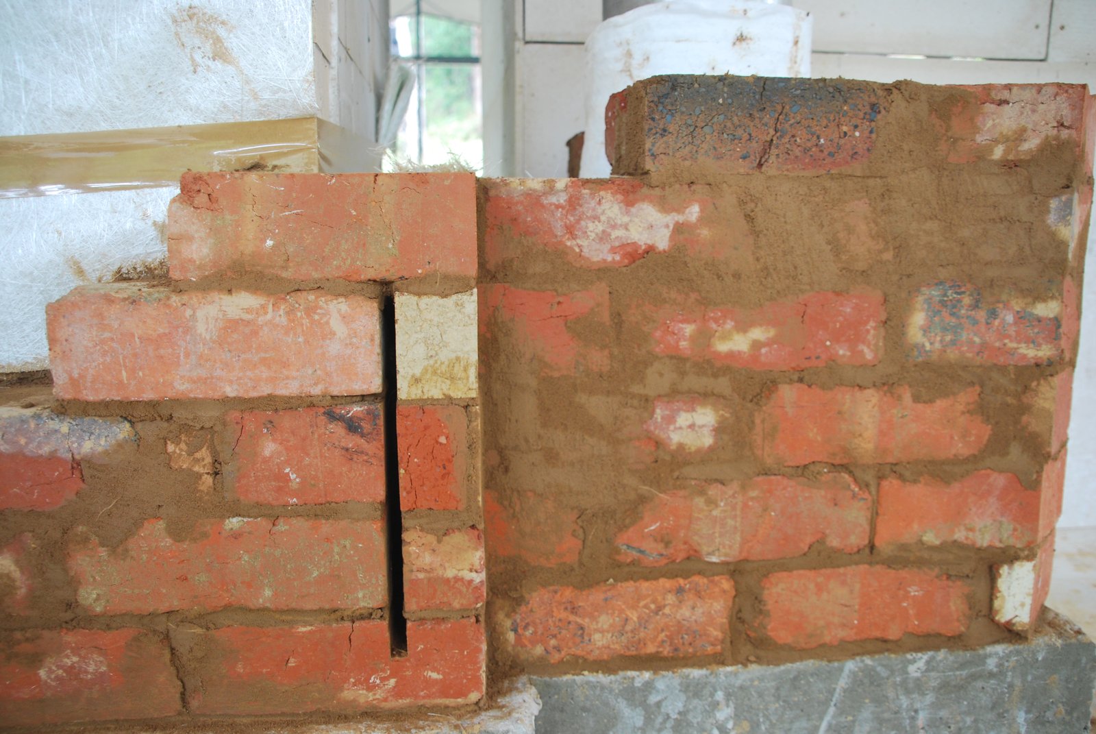
Once the two openings are bridged the chimney starts to corbel in to its final dimensions.
After this course an open joint of approx. 7 mm will be maintained between the chimney and the heaters facing.
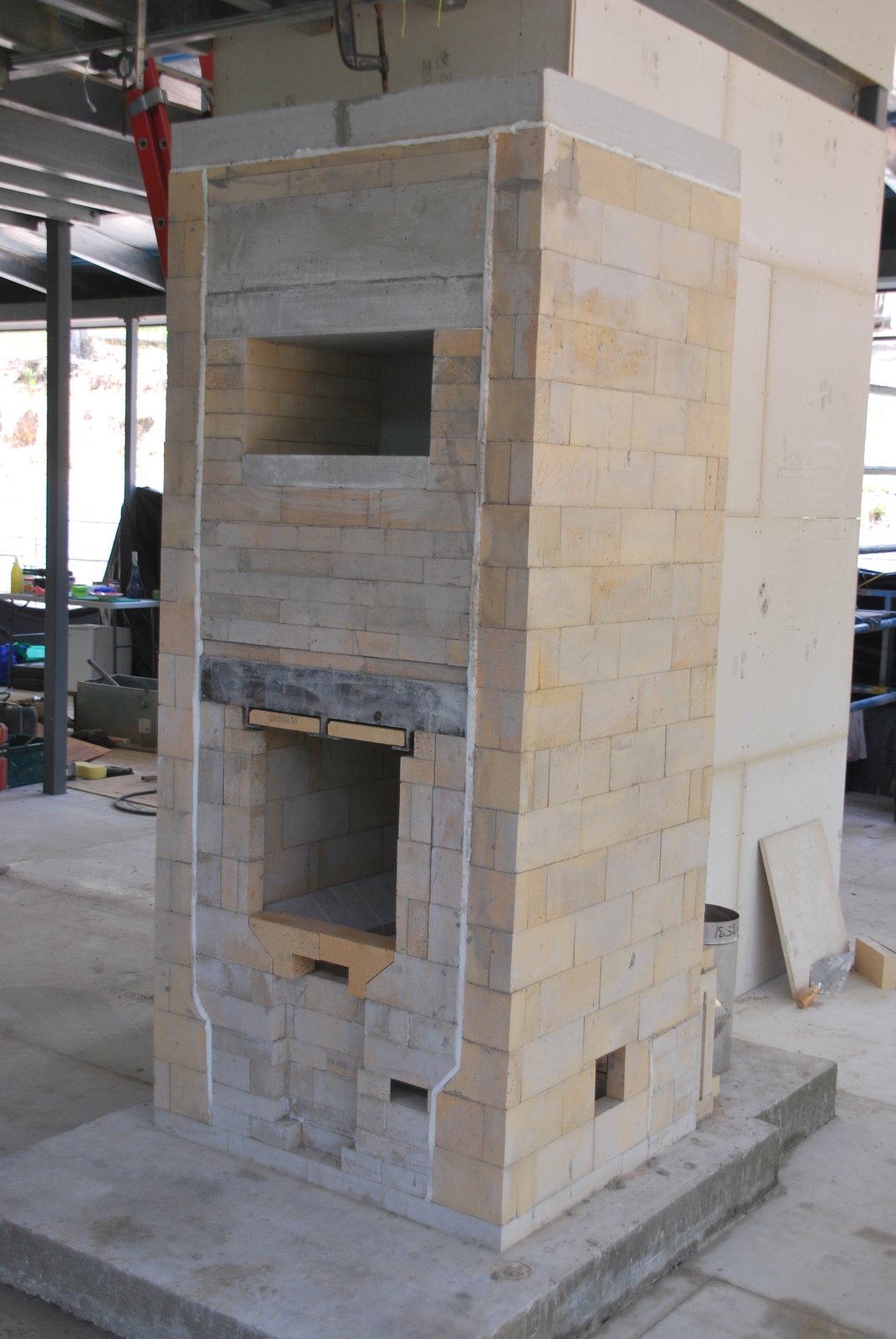
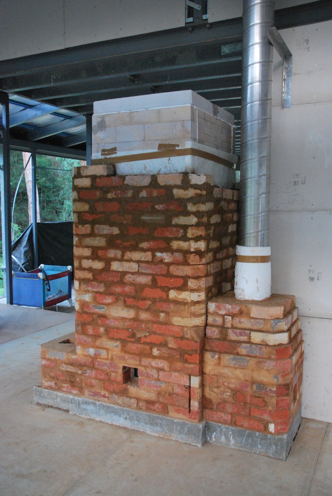
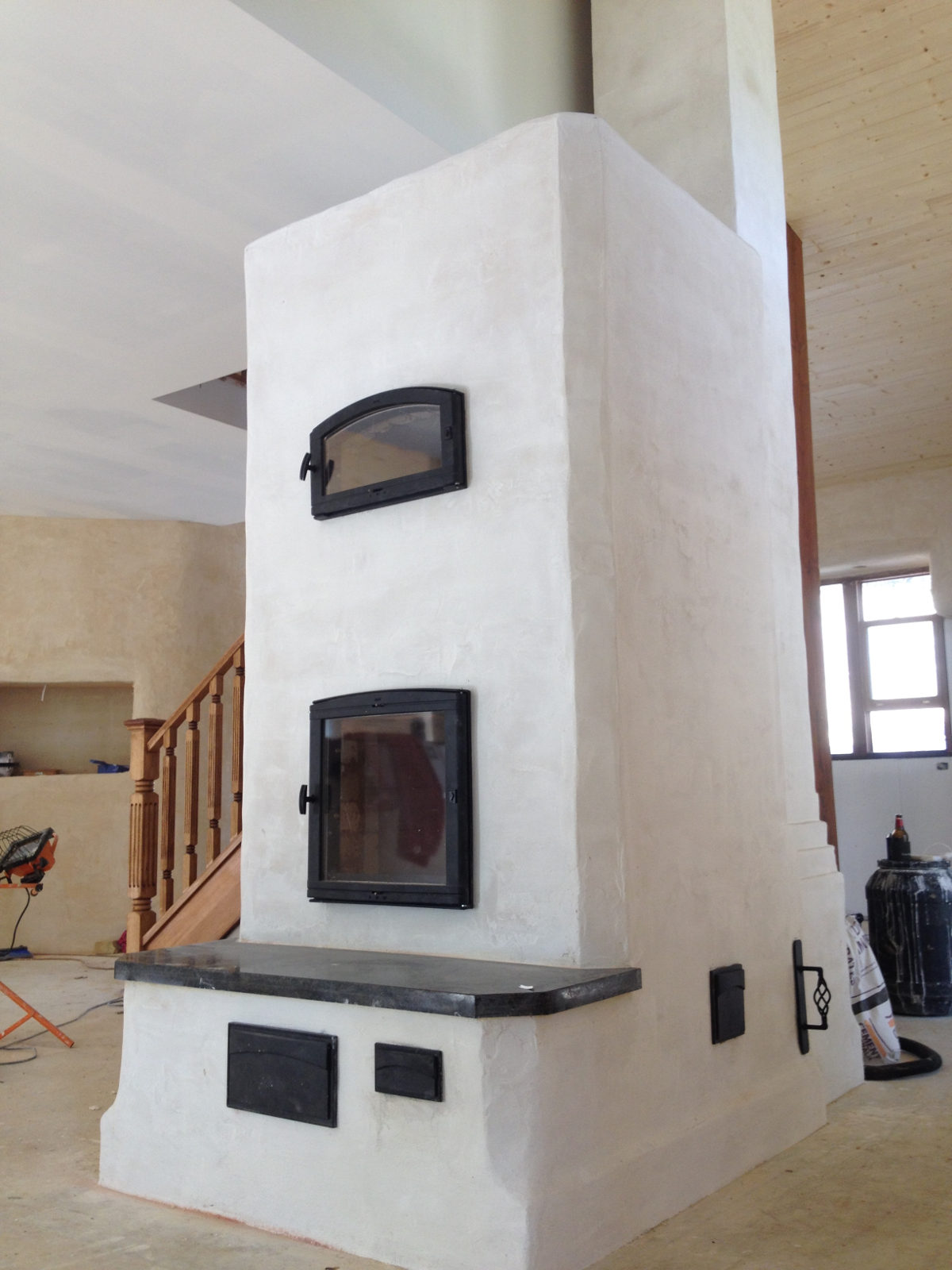
The remainder of the facing, the chimney, rendering and installation of the hardware will be done by the home owner.
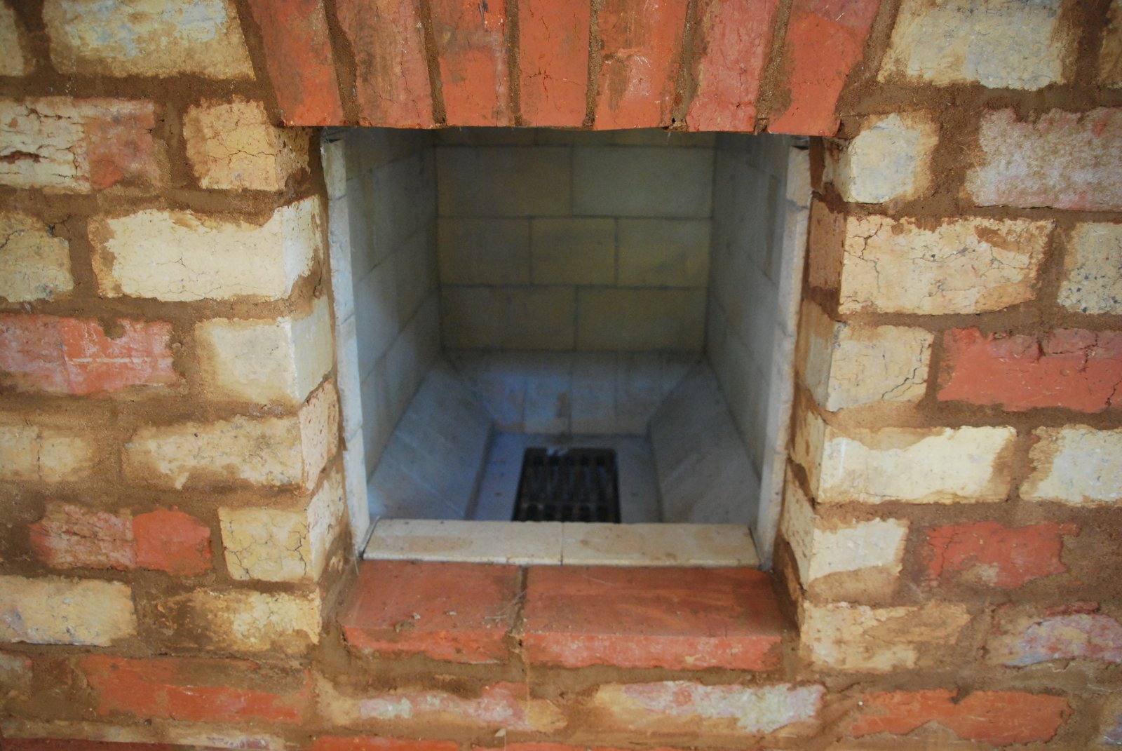
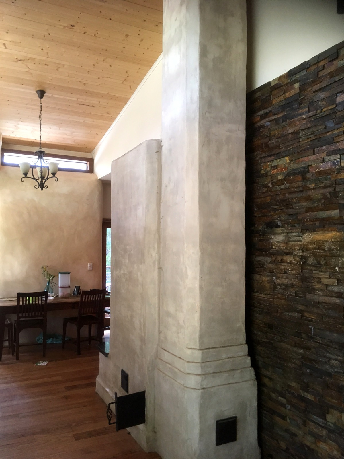
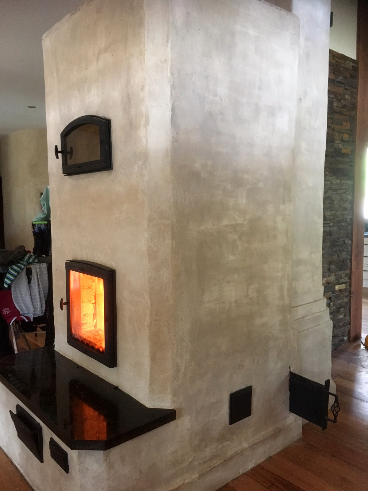
The stove as finished by the homeowner prior to the Southern winter of 2015.
The stove as finished by the homeowner prior to the Southern winter of 2015.
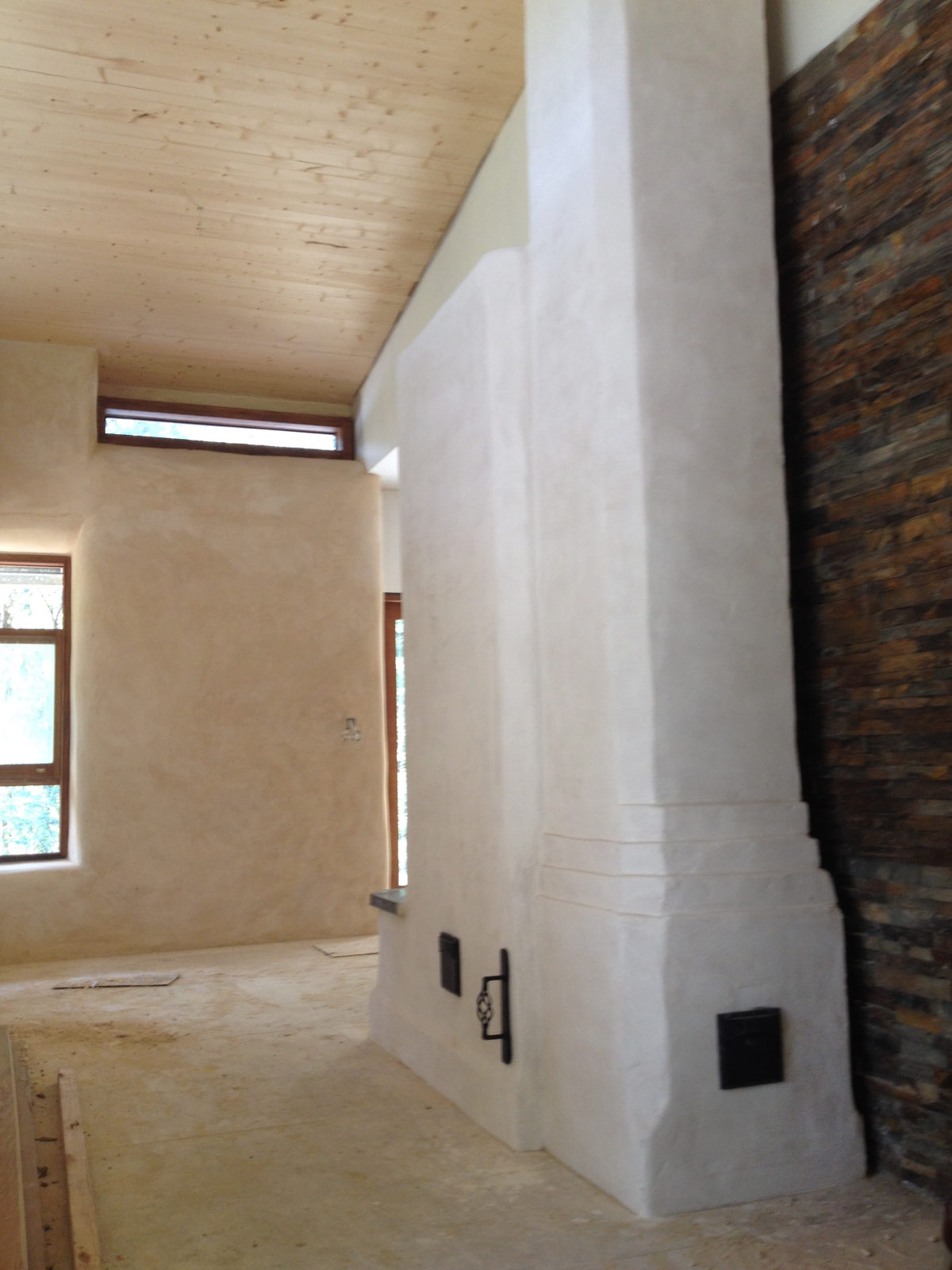
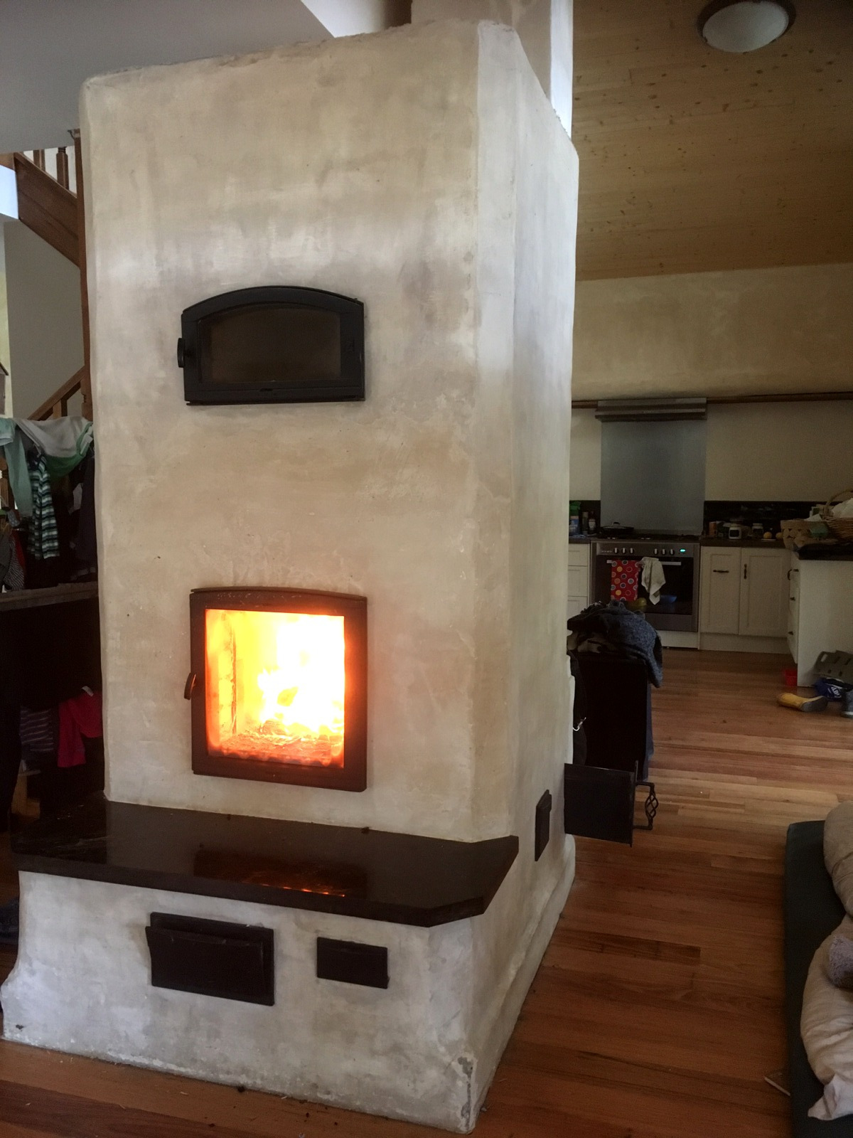
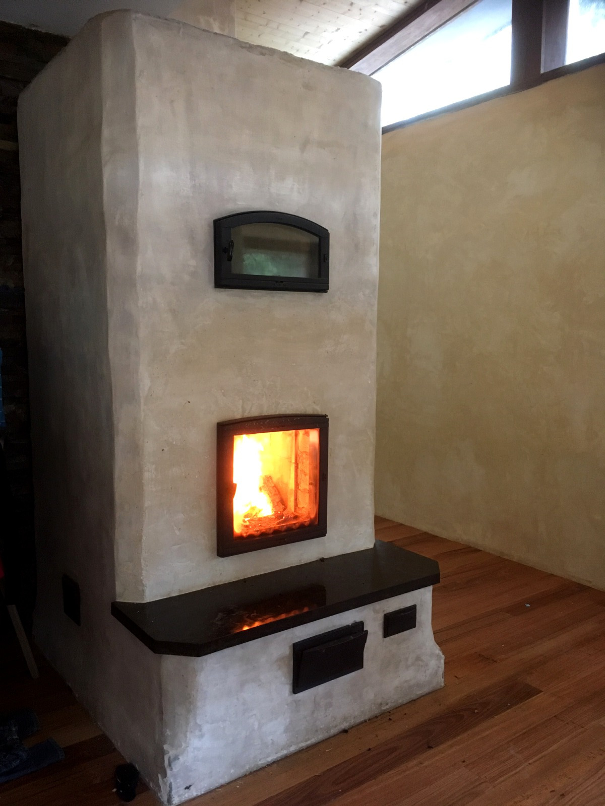
Images of the finished interior: 2017
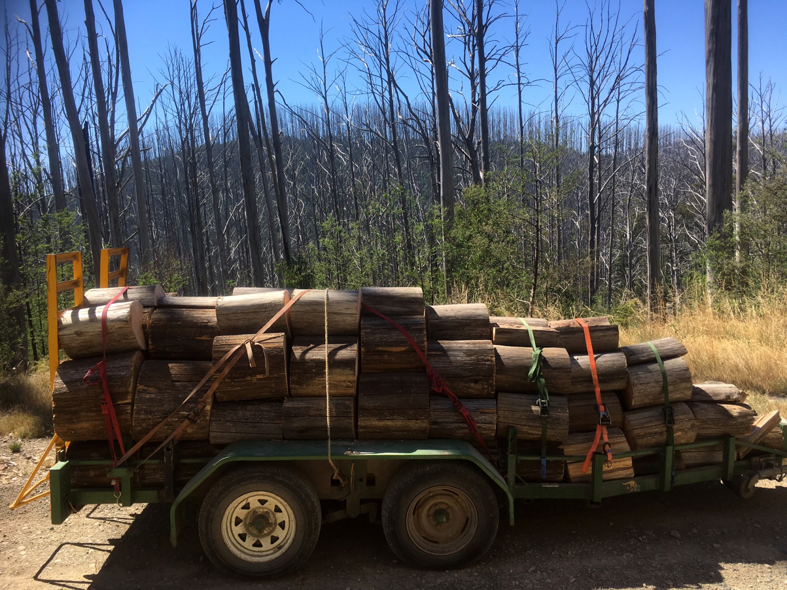
"About 30 km up the mountain is where the 2009 fires went through and the heat from the fire was so intense it seemed to petrify the trees, instantly sucking all moisture from them and have just died standing up. Its quite an amazing feeling to be up there and as far as the eye can see is just 40 meter high tooth-picks. So plenty of wood for next 20 odd years."