Finnish style contra-flow refractory core and facing.
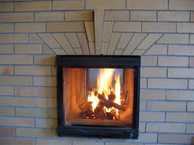
The heater will have a fire box loading opening on both front and rear faces,
and be connected to an existing chimney flu by a custom built transmission tunnel.
Materials:
Facing Brick: 900 custom made brick, by Terres Cuites de Berry were used in the project.
The brick are extremely dense 2.1 tonnes/m3, having all air removed from the mix by vacuum pump before extrusion.
Though the brick factory is only 60 km from the site the majority of the clay in the mix is from the region around Moulin.
The addition of carbon to the mix and its reaction to oxygen during firing gives the brick its desired cream colour.
As testimony to their local artisanal production the brick arrived warm, followed, several days later,
by an equally warm visit from the factory's owner.
All facing brick are layed in type N mortar.
Hardware: Cast iron hardware is by Upo of Finland.
Refractories:
Brick
720 Bony B40N French format.
Castable refractory concrete
Refracol Cast 1380/10
Incombustible blanket
TC Superwool 607 max 128 13 1362T
Note: Any images or notes regarding projects inspired or assisted by
this article, if sent to Pyromasse, will be posted
on to a page specially created for such comment.
See also: Technical Documents PDF Index
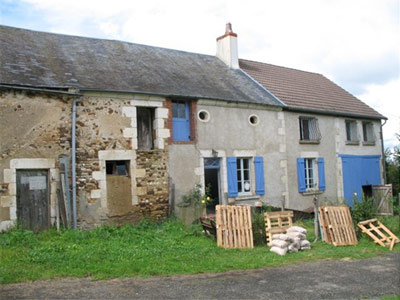
The site. And my place of abode during the project.
The original portion of the farm house was built approximately 180 years ago.
The extension to the right is considerably younger, probably early 20th century.
All period masonry in the building is layed in earth and lime mortar.
Modern repairs have been undertaken in lime, sand mortar.
Cat paw prints.
Kitchen
Graffiti
Kitchen and bathroom
Inside the oven
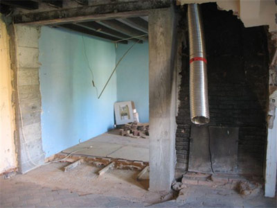
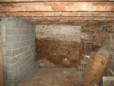
The heater will be located in the centre of the two principal ground floor rooms,
directly on the line of the load bearing wall that separates the original from the
added portions of the building. It will be connected to the flexible stainless steel
flue that lines the original chimney flue. The black portion of the wall was the back
of the principal ground floor fire place.
The wall between the two rooms was opened in preparation for the project.
The opening would accommodate the heater and a future stairway.
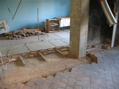
The load bearing wall extends down into the basement forming the division between
a traditional vaulted cellar, beneath the original portion of the house, and the
modern vaulted cellar of the extension.
The load bearing wall is 0.50m thick on the ground floor and contains one central
chimney flue into which both the original ground floor fire places and the kitchen oven feed.
The steel I-beams of the modern vaulted cellar ceiling are supported upon the concrete slab on which the heater will rest.
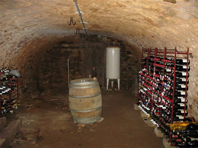
Vaulted basement beneath original portion of the building, with load bearing wall to the right.
The more recent cellar with the load bearing wall at left.
The block and concrete pier partially supports the heater's foundation slab on the first floor.
The cellar roof is formed by numerous masonry arches springing from a series of parallel steel I-beams.
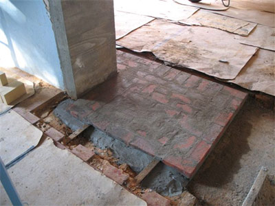
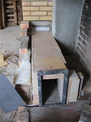
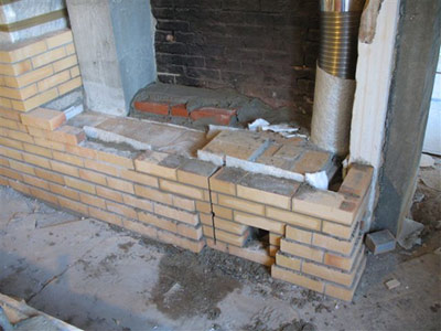
The first of two base courses is layed. This course represents the foot print of the heater including facing.
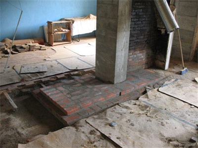
The second base course represents the footprint of the core.
Due to a misinterpretation of plan, the concrete foundation slab was only large
enough to accommodate the heater, meaning that the whole transmission tunnel and
chimney connection would rest upon the original clay tile floor.
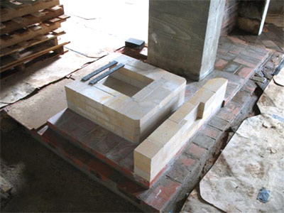
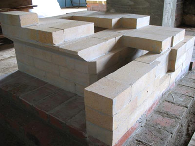
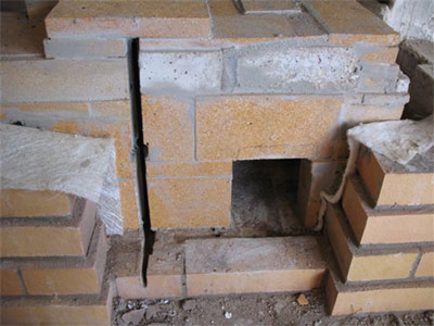
The first three courses of the core. The ash box was set up to take a steel ash tray,
though as the project advanced it was decided to abandon this method of ash removal.
The problem with a tray that is removed from the ash box, (air intake door) is that
it would allow primary air into the void beneath the grate, causing an under draught.
The opening in the front of the ash box (to remove the tray) was sealed with masonry.
The ashes will be removed directly from the fire box.
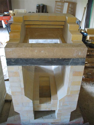
Bridging of the rear manifold.
The heater will have two fire box loading openings, and two primary air intake doors, one beneath each fire box door.
Note the cutout primary air channel in the rear manifold wall and on the far side of the hearth.
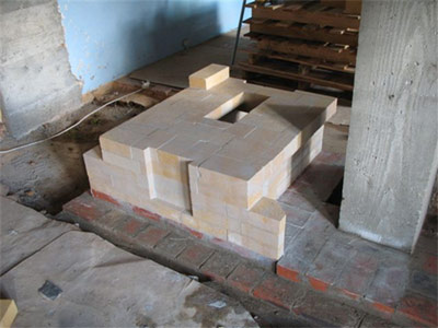
The grate is not centred front to back as at this point we were still attempting to have the ash
fall into a steel tray that would be removed via the primary air intake door on the far side of the core.
The sloped fire box floor, and fire box wall.
The splits on the inside of the fire box wall act as a liner that can be replaced if at any time in the future it becomes damaged.
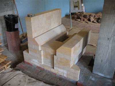
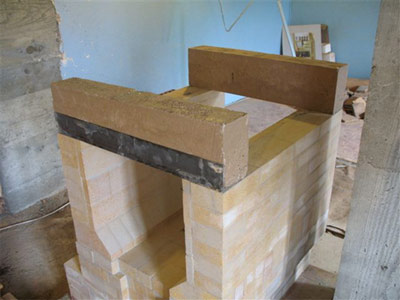
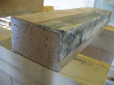
The fire box lintels were poured in castable refractory concrete.
An 80cm x 80cm x 6mm angle iron was placed in the mold before the lintel was poured.
This provides support in the event that the lintel should crack.
Both lintels are far enough away from the fire that flame bite on either castable or angle iron is not an issue.
Secondary air entering through the draught slide in the top of the door will pass over the lintels.
The lintels were cast to the height of three rows of brick.
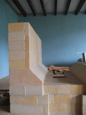
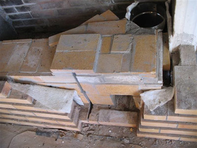
Outside view of the masonry as it corbels off the lintel.
Each side will have an identical corbel, eventually arriving at an 18cm opening.
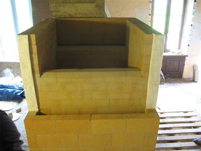
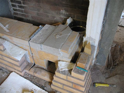
The core with partially built side channel.
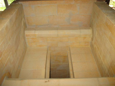
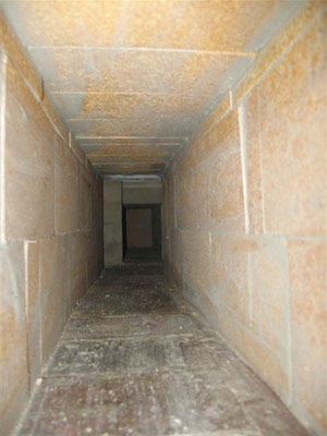
View inside the upper chamber. Wide throat at 7 inches. Tight channels at 2 inches.
Looking up towards the 3 capping slabs.
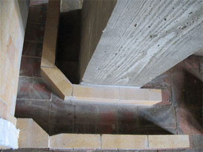
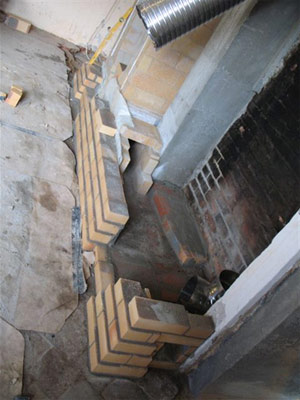
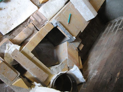
Over head view of the transmission tunnel as it leaves the side manifold.
The opening in the side channel wall and the tunnel are bridged by a single piece
of castable refractory concrete sawn to shape. The tunnel it self is bridged with brick.
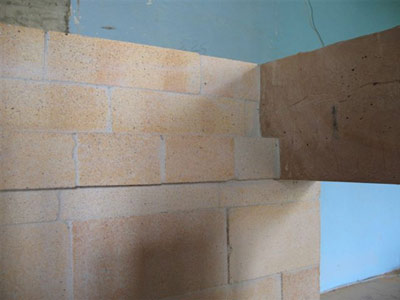
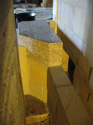
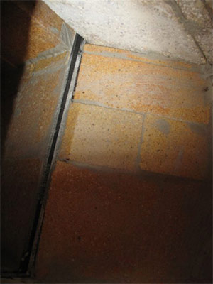
View of the tunnel's connection to the side channel, from the opposite room.
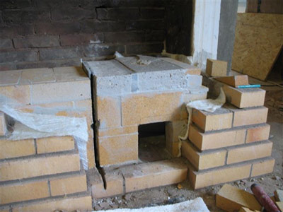
The first two courses of the side channel above the lintel.
View down the side channel towards the tunnel's connection.
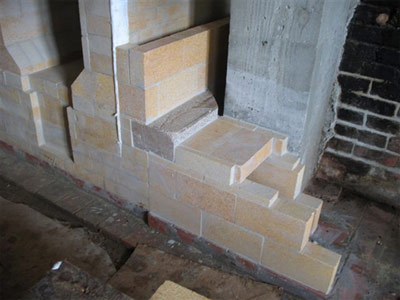
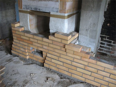
The first courses of facing brick were layed in order that the heaters facing
could progress above the tunnel's connection to the side channel.
The living room.
Due to the necessity of having both manifold access doors, and the air intake door
openings on the same face, a broken corbel was not attempted.
The expansion gasket between core and facing is 400g glass fibre mat.
3 sheets thick on the front and back, for expansion, and a single sheet on each side as a slip joint.
The 4 course corbelled skirt is cut back to allow the opening for the primary air intake door.
Note: the first brick of the final corbelled course of the tunnel.
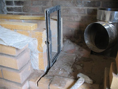
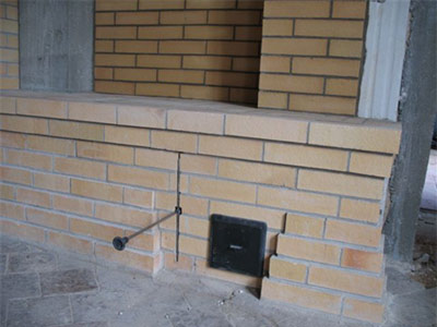
The Finnish fabricated cast iron shut off trap is located a close as possible to the chimney connection.
The two damper frame plates are recessed into the base course of clay brick,
to eliminate drag from a protruding frame, and help diminish the overall height
of the frame which is about 2 cm higher than capping brick of the tunnel.
The frame sitting in the recess helps keep it stable and eliminates the possibility
of the frame moving out of position as a result of regular operation.
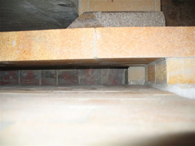
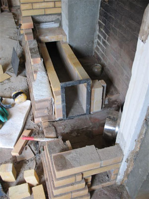
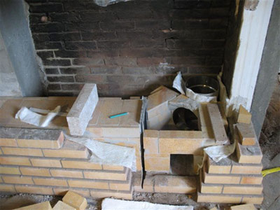
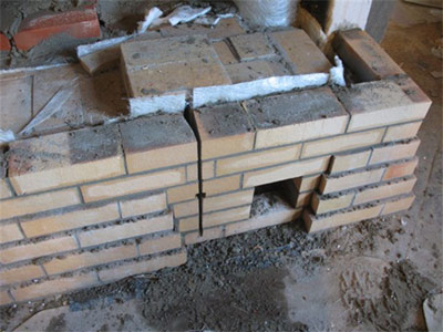
The finished transmission tunnel with the damper frame in position. The guillotine plate is to the left.
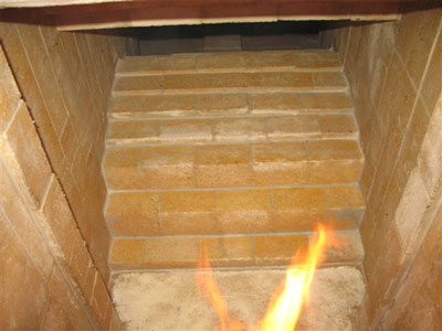
View down the transmission tunnel into the heater's rear manifold.
The chimney flue connection and damper plate.
This portion of the tunnel is particularly detailed as there are four openings within such a small area.
The damper frame, the stainless steel elbow, and two 5 x 5 inch access openings
in the face and side of the connection, all fall within the confines of 1 cubic foot of masonry.
The chimney connection is bridged by pieces of castable refractory concrete.
The glass fibre mat gasket between the tunnel and facing has only one sheet on the
sides and 3 on the end of the tunnel.
(Two sheets will be placed on to the top before concrete is poured over the whole tunnel.)
The damper plate slot must be cut in to the first course of clay brick, to allow the plate to be pulled through the facing.
The two portions of masonry each side of the damper plate are tied together with scrap pieces of refractory brick.
The cut in the corbelled skirt as it is about to be closed.
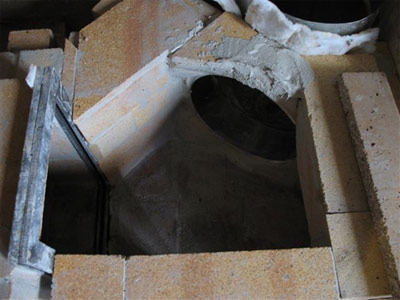
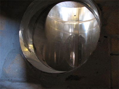
View of the 200mm round stainless elbow inside the chimney connection.
The damper frame plates inside the tunnel. Note the castable refractory concrete capping the connection.
The back of the facing brick each side of the damper slot are cut back to avoid the plate catching the corners as it is drawn out.
Once the two corbelled courses of the tunnel's facing have been layed, concrete
will be poured over the whole tunnel and chimney connection (unfortunately there are no images of this step).
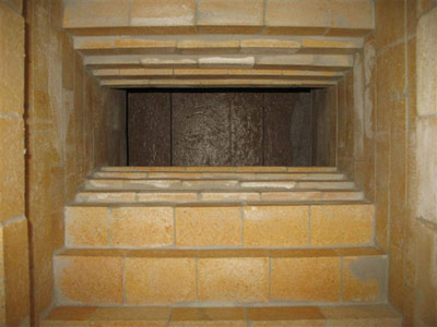
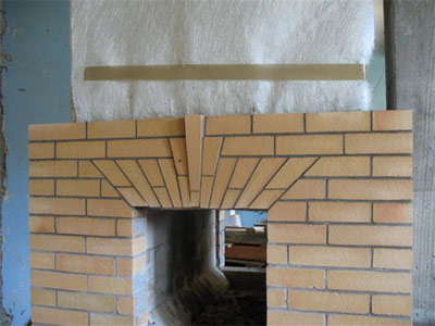
Jack arch over one of the fire box loading openings.
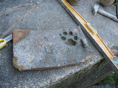
The dog paw print on the back of this ancient clay roof tile, formally used as
a soap tray, will be cut out and inserted into the façade of the heater.
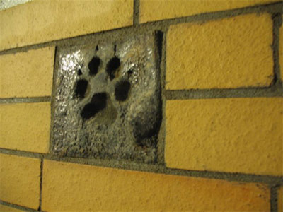
The section of roof tile, cut into the façade.
Detail of the damper slot and chimney connection access door.
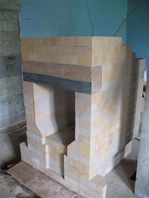
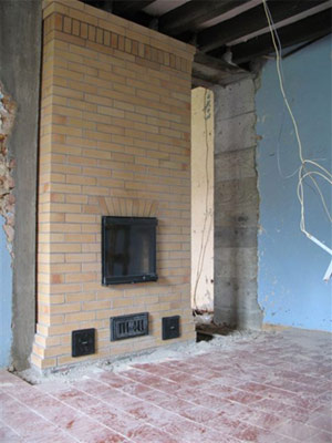
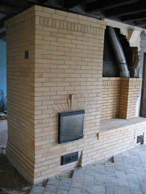
View from the living room. The staircase will run through the opening to the right of the heater.
Note the piece of roof tile inserted in the upper right of the side channel.